background image

Manual of Board ET-TOUCH PAD  4x4 V2 


www.etteam.com 

-

17

1

3

2

4

5

6

7

8

9

0

SHIFT

HELP

ENTER

CLEAR


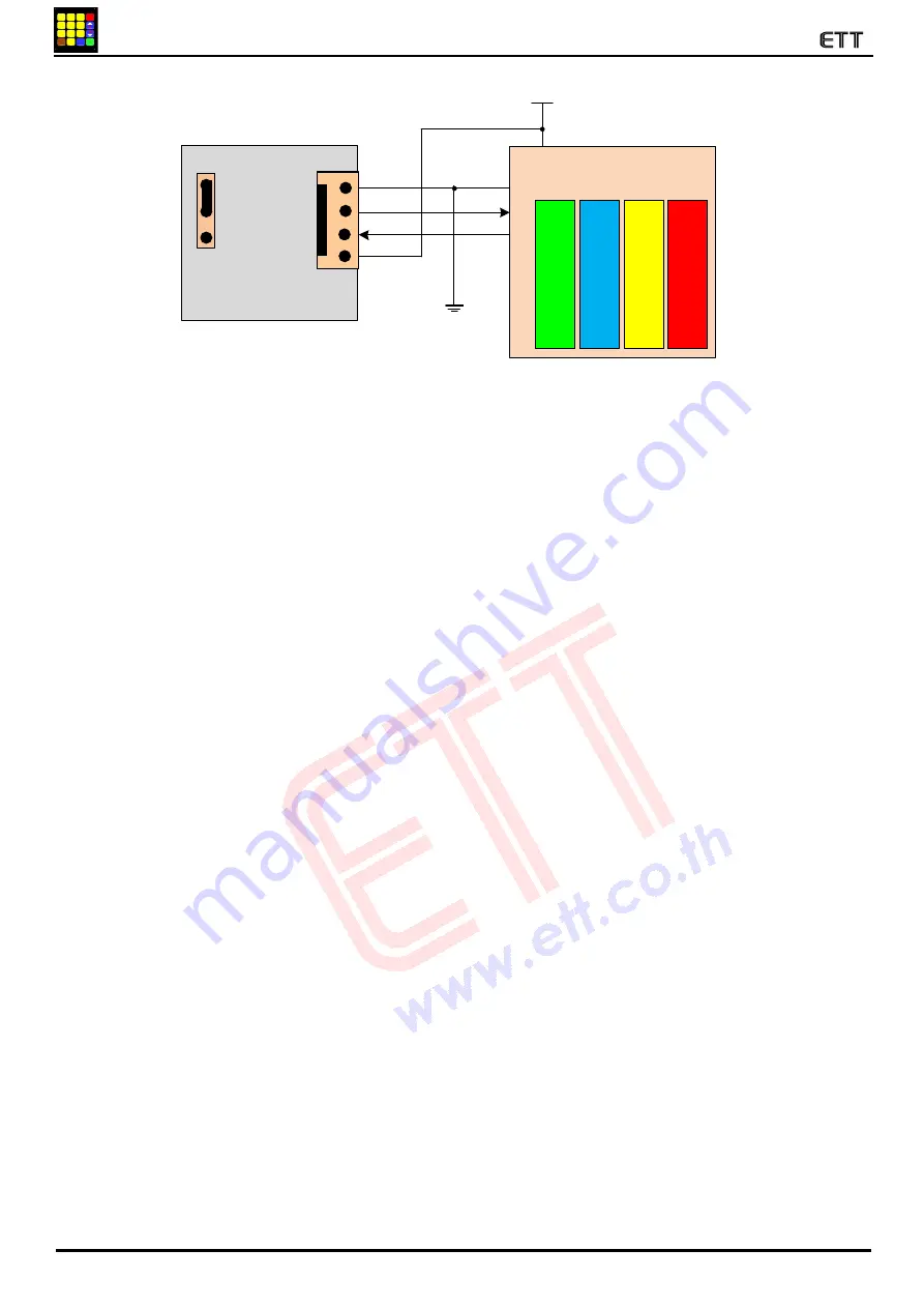
Figure 5.9 shows how to connect circuit to read Key Code as ASCII of Board MCU and ET-TOUCH PAD 4x4 V2 (TTL). 


Ex2_Read_ASCII_ShifKey

: This example illustrates how to read Key Code as ASCII. It presses Key F together with another Key and it uses 

Interrupt to setup interval of receiving data. In the part of Display, it shows ASCII Code in the format of HEX through 
Port of MCU that is connected with LED. 
 

When user starts touching any Key, program skips to receive incoming data and store until all 3 Byte Data is 

completed. Next, it checks if the last Byte is 0x0D; if yes, it means that it received all 3 Byte Data completely and it is 
correct. Next, it returns to check if the first Byte that received is ASCII ‘P‛; if yes, it means that it touched Key. It checks 
the received Data in the second Byte that is ASCII Key Code of the touching Key; it checks if the value is equivalent to 
ASCII CODE ‘F’; if no, it means that it presses single Key, Program sends the second ASCII CODE Byte to display in 
the format of Hex through Port of the connective LCD. For example, if touched Key 0, the ASCII Code in the format of 
Hex is 0x30 (NOTE: For the example of Arduino, it can display the result of touching Key in the range of Key0-Key9 
only). If the Key that is touched is Key F, Program loops and waits for receiving the second Key that is pressed together 
with Key F. When touched the second Key, Program checks if the last Byte Data is equal to 0x0D; if yes, it returns to 
check if the first Byte is ASCII ‘F’; and if yes, it means that it pressed the second Key together with Key F. So, Program 
sends the second ASCII CODE Byte of the touched Key to display in the format of Hex through Port of the connective 
LCD. For example, if touched KeyF+Key9, the ASCII Code in the format of Hex is 0x39 (NOTE: Other Keys that can be 
pressed together with Key F in this Program must be in the range of Key0-Key9 only). Finally, after touched completely, 
Program returns to read the Data again to check Data of releasing Key. If the first Byte Data is ASCII ‘R’, it means that it 
has already released Key; so, Program returns and waits for reading Data of the next touch. The circuit connection that is 
used to test this program is the same as the example 1 above. 


Board

ET-TOUCH PAD 4x4 V2

Board MCU 

Vcc

Rx

Tx

Gnd

+VDD

RX(TTL)

TX(TTL)

GND


 +5V

T

T

L

2

3

2

 (

7

)

Interface 232TTL

A

T

m

e

g

a

1

6

8

(A

rd

u

in

o

)

D1

D0

TTL232

RS232

J

P

-2

3

2

(4

)

A

T

m

e

g

a

1

2

8

PE0

PE1

P

IC

1

8

F

8

7

2

2

RC6

RC7

P3.0

P3.1

8

9

C

5

1

R

E

2

Baud Rate=9600

Содержание ET-Touch PAD 4x4 V2

Страница 1: ...CONNECTOR 8 PIN Pin T R and SHIF shows status of pressing or releasing Key 2 ASCII Code Send value though Connector RS232 TTL and Line Driver setup fixed Baud Rate at 9600 ASCII P or R preceded Key Code to notify status of pressing or releasing Key If Key Touch Pad is made from translucent plastic it is 1 3 millimeters thick depending on humidity in the air If it is made from other materials the t...

Страница 2: ...wn in the figure above While assembling both parts together please notice direction of the arrowhead or cut angle PCB of MCU Control Board it must be the same direction as shown at the back of Touch PAD Board and finally user can assembly both parts together Figure 2 2 shows the front of Touch PAD Board Figure 2 3 shows the front and the back of MCU Controller Board 7 TTL232 6 JP LED 5 JP BZ 3 RS2...

Страница 3: ...SCII Moreover it can receive user s Command to control operating system of Buzzer and LED STATUS while no KEY is pressed for more information please read COMMAND for CONTROL LED BUZZER Figure 2 4 shows Connector RS232 Line Driver for sending Command and reading Key Code as ASCII Code Details of each PIN VDD GND Interface Power Supply for Board that is either VDC 3 3V for MCU 3 3V or 5V for MCU 5V ...

Страница 4: ...oss line between RX TX while connecting The operating system of this Connector is the same as Connector RS232 No 3 but the signal level only is different because it is lower so it can be connected with Pin MCU directly Figure 2 6 shows Connector TTL232 to send Command and read Key Code as ASCII CODE Details of each PIN VDD GND Interface Power Supply for Board that is either VDC 3 3V for MCU 3 3V o...

Страница 5: ...ther ASCII Code or Binary Code because it has to choose only one Connector type correctly If reading Key Code as ASCII Code it has to choose Connector RS232 3 or TTL232 7 or if reading Key Code as Binary BCD8421 it has to choose Connector O P BCD Key Code 10 In the part of Power Supply VDD GND for Board user can choose only one Connector to interface signal it is either Connector RS232 3 or TTL 7 ...

Страница 6: ...e is set as follows PIN SHIF 1 PIN T R 1 PIN8 0 PIN4 0 PIN2 0 PIN1 0 Figure 3 1 shows the Initial Status Default at Pins of Connector 8 Pin KEY FOR Binary MODE FOR ASCII Mode RS232 TTL Line Drive BCD 8421 KEY CODE ASCII KEY CODE 8 4 2 1 HEX ASCII HEX 1 0 0 0 1 0x01 1 0x31 2 0 0 1 0 0x02 2 0x32 3 0 0 1 1 0x03 3 0x33 4 0 1 0 0 0x04 4 0x34 5 0 1 0 1 0x05 5 0x35 6 0 1 1 0 0x06 6 0x36 7 0 1 1 1 0x07 7 ...

Страница 7: ...ssing the 2nd Key that is the remaining Key Key F is still pressed PIN T R is still Logic 0 but PIN SHIF changes the status from Logic 1 to 0 and the status still remains throughout while pressing Key F another Key 4 PIN BCD8 4 2 1 sends out Key Code of the 2nd Key to user Figure 3 3 shows example of status at PINs of Connector 8PIN when pressing Key F together with another Key Key F Key3 Status o...

Страница 8: ...ng both Keys that are pressed together the status of both Keys is also changed to Logic 1 3 2 How to read Key Code as ASCII When reading Key Code as ASCII user can read the value from Connector RS232 or TTL232 it is Serial Port Interface and the Baud Rate is fixed as 9600 bit s When choosing Connector type it depends on Port 232 of Board that is connected with Touch PAD it is either TTL or IC Driv...

Страница 9: ...ET TOUCH PAD sends out is ASCII F 0x46 the second Byte is ASCII Key Code of the pressed Key and finally the last Byte is 0x0D to end Table shows the format of sending Data when pressing 2 Keys together NOTE When pressing 2 Keys together there are 2 sets of Data that are sent out The first set is Byte Data of Key F that is ASCII P it is sent out to notify that it is status of pressing Key and its f...

Страница 10: ... both Keys that are pressed together 4 How to send Command Control Buzzer LED Status Key In the part of Port 232 it can send ASCII Key Code to user moreover it can support ASCII Command from user to control the operation of Buzzer and LED Status Key on Board The main target is to use Buzzer and LED Status Key as Alarm Function when it does not press any Key but when it presses any Key Key returns ...

Страница 11: ...Byte1 Byte2 3 Byte4 Byte5 Byte6 BP 0 9 Enter 0x0D Respond Command จำก Board OK Data 0 9 Length of Beep sound When setting 1 Beep sound is the shortest 0 Beep sound is the longest Ex Send Command to produce Beep sound and set the length of Beep sound as level 5 Main char enter 0x0D printf BP 5 enter Sent Command Beep 3 COMMAND LE LED ENABLE This Command ON LED Status Key is to turn on all LED at on...

Страница 12: ...olum1 4 ดวง 2 OFF LED Colum2 4 ดวง 3 OFF LED Colum3 4 ดวง 4 OFF LED Colum4 4 ดวง 5 OFF LED Row1 4 ดวง 6 OFF LED Row2 4 ดวง 7 OFF LED Row3 4 ดวง 8 OFF LED Row4 4 ดวง Ex Send Command to turn off all LED at once Main char enter 0x0D printf LD 0 enter Sent Command OFF LED ALL NOTE When sending Commands consecutively it always checks status of Respond Command between Commands that are sent out or it ma...

Страница 13: ...the connective LED except Arduino it does not display any data in this part and finally it types the Key Code to display data at Hyper Terminal on PC For example if touched Key 5 LED shows the value as 0x05 and Hyper Terminal also shows message Key_Code BCD 0x05 Next MCU will check Signal T R again to check the status of releasing Key T R 1 When released Key completely the program returns to check...

Страница 14: ...ey T R 1 If the pressed Key is Key F the program loops to read Key Code of another Key that is pressed together with KeyF It checks Signal SHIF if it is 0 it means that another Key is pressed together with Key F Program reads Key Code of the second Key from Connector BCD8421 and it sends out the Key Code through Port to display the data on the connective LCD except Arduino it does not display any ...

Страница 15: ... Display and MCU please look in Source Code The operation in the part of reading Key Code is the same as the example 2 above but it is different in the part of Program that responds to pressing Key only In the part of LCD Display it shows the message as shown in the figure 5 5 if it does not press any Key Figure 5 5 When pressing 1 Key that is not KeyF such as Key 8 LCD Display shows the message a...

Страница 16: ...ving data In the part of Display it shows ASCII Code in the format of HEX through Port of MCU that is connected with LED When user starts touching any Key program skips to receive incoming data and store until all 3 Byte Data is completed Next it checks if the last Byte is 0x0D if yes it means that it received all 3 Byte Data completely and it is correct Next it returns to check if the first Byte ...

Страница 17: ...0 the ASCII Code in the format of Hex is 0x30 NOTE For the example of Arduino it can display the result of touching Key in the range of Key0 Key9 only If the Key that is touched is Key F Program loops and waits for receiving the second Key that is pressed together with Key F When touched the second Key Program checks if the last Byte Data is equal to 0x0D if yes it returns to check if the first By...

Страница 18: ...am com 18 1 3 2 4 5 6 7 8 9 0 SHIFT HELP ENTER CLEAR PCB LAYOUT PCB LAY OUT 1 2 3 4 A 5 6 B 7 8 9 C 0 F D E 4mm 4mm 3 3mm 2mm 7 7mm 13 45mm 16 6mm 16 51mm 88 9mm 76 2mm 10mm 13 2mm 19 65mm 16 6mm 16 51mm PCB Dielectric 2mm 38 1mm 20mm Under Side ...

Страница 19: ...Manual of Board ET TOUCH PAD 4x4 V2 www etteam com 19 1 3 2 4 5 6 7 8 9 0 SHIFT HELP ENTER CLEAR ET TOUCH PAD 4x4 V2 Sheet1 ...

Страница 20: ...Manual of Board ET TOUCH PAD 4x4 V2 www etteam com 20 1 3 2 4 5 6 7 8 9 0 SHIFT HELP ENTER CLEAR ET TOUCH PAD 4x4 V2 Sheet2 ...

Страница 21: ...Manual of Board ET TOUCH PAD 4x4 V2 www etteam com 21 1 3 2 4 5 6 7 8 9 0 SHIFT HELP ENTER CLEAR ET TOUCH PAD 4x4 V2 Sheet3 ...

Отзывы: