background image

Kuvamateriaali on havainnollistava

Pidätämme oikeuden muutoksiin

RDT-07-0121

45

®

NORD

fire


|


FDMB

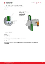
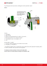
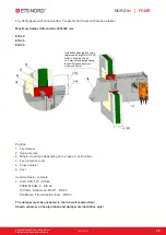
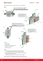
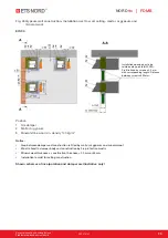
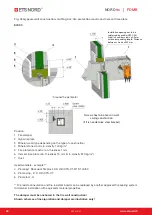
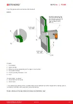
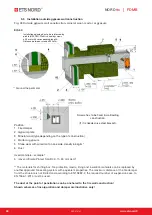
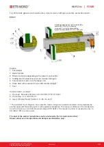
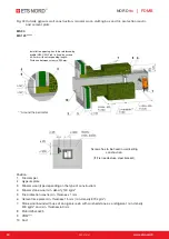
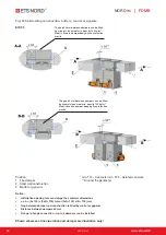
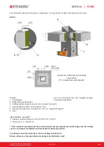
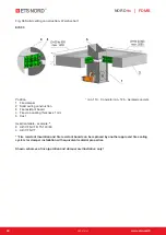
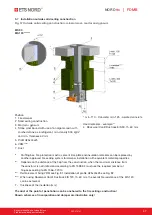
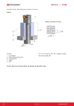
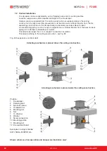
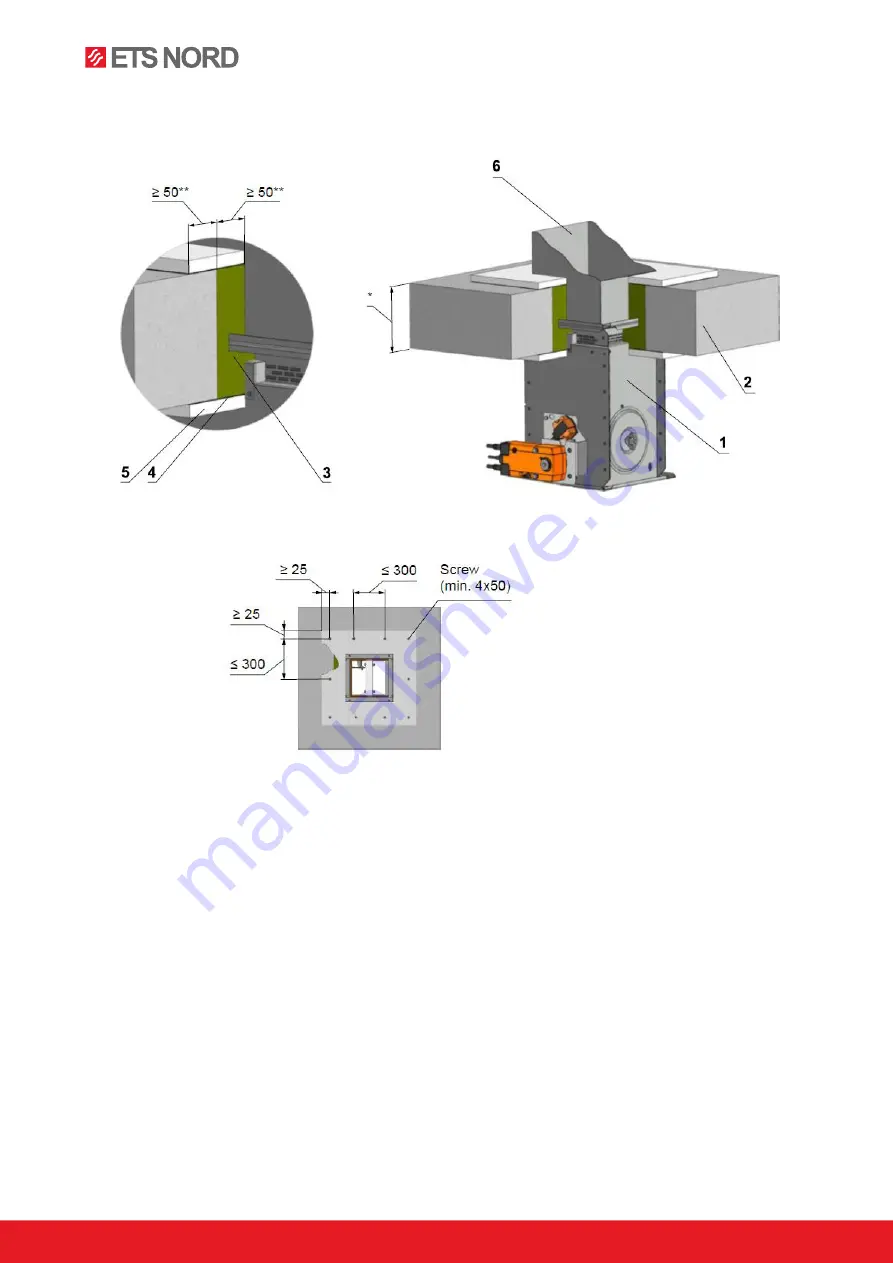
Fig. 55 Solid ceiling construction- stuffing box, fire protection mastic and cement lime plate

EIS 90

Position:                                                                          * min. 110 - Concrete/ min. 125 - Aerated concrete

1   Fire damper                                                                ** Around the perimeter

2   Solid ceiling construction

3   Stuffing box (mineral stone wool min. density 140 kg/m³)

4   Fire protection mastic min. thickness 1 mm

5   Cement lime plate min. thickness 15 mm, min. density 870 kg/m³

6   Duct

Used materials - example:*** 

3   Promapyr, Rockwool Steprock HD, Hilti CFS-CT B 1S 140/50
4   Promastop - P, K, Hilti CFS-CT

*** Fire resistant insulation and fire resistant board can be replaced by another approved fire sealing 

system for damper installation with equivalent material properties.

The damper must be anchored to the fire ceiling construction!
Shown schemes of incorporation and damper are illustrative only!

Screws has to be fixed in wall/ceiling 

construction.

(If it is needed use steel bracket).

Содержание NORDfire FDMB

Страница 1: ...e dampers from 160 160 mm to 0 5 m2 max dimensions 1000 500 mm CE certified acc to EN15650 Fire resistance up to EIS 120 External Casig leakage class C Internal leakage class 2 acc to EN 1751 Damper actuating mechanical or electrical ...

Страница 2: ... on BAT is pushed or when a power supply of the actuating mechanism is stopped The damper is sealed with a silicon packing against smoke penetration after closing the blade At the same time the damper blade is bedded in a material which enlarges its capacity and air proofs the air duct Dampers have two inspection holes 1 2 Damper characteristics CE certified acc to EN 15650 Tested in accordance wi...

Страница 3: ...echanical control with a thermal protective fuse which actuates the shutting device after the nominal start temperature 72 C has been reached Automatic initiation of the shutting device is not activated if the temperature does not exceed 70 C In case that other start temperatures are required thermal fuses with nominal start temperature 104 C or 147 C can be supplied this requirement must be speci...

Страница 4: ...d maximal current AC 230 V 5A Class of protection IP 67 Working temperature 25 C 120 C Fig 7 Change of mechanical design for the motorised one or vice versa 1 Damper 2 Mounting plate 3 Sealing cover 4 Seal plates 5 Mounting plate cover 6 Thermal fuse 7 Mechanics 8 Actuator 9 Temperature sensor 10 Sensor sticker Limit switch OPEN Limit switch CLOSED This limit switch is possible to connect in follo...

Страница 5: ...ck spring displaces the damper blade into the breakdown position CLOSED The time of displacing the blade from the position OPEN to the position CLOSED takes maximum 20 sec In case that the power supply is restored again the blade can be in any position the actuating mechanism starts to re displace the damper blade into the position OPEN A thermoelectrical starting mechanism BAT which contains two ...

Страница 6: ...oning 6 5 10 VA Imax 4 A 5 ms 4 6 VA Imax 8 3 A 5 ms Protection class II III Degree of protection IP 54 Running time motor spring return 60 s 20 s Ambient temperature normal duty safety duty non operating temperature 30 C 55 C The safe position will be attained up to max 75 C 40 C 55 C Connecting motor auxiliary switch cable 1 m 2 x 0 75 mm BFL BFN 24 T ST with 3 pin plug in connectors cable 1 m 6...

Страница 7: ... W Dimensioning 10 VA Imax 8 3 A 5 ms 12 5 VA Imax 500 mA 5 ms Protection class III II Degree of protection IP 54 Running time motor spring return 120 sec 16 sec Ambient temperature normal duty safety duty non operating temperature 30 C 55 C The safe position will be attained up to max 75 C 40 C 55 C Connecting motor auxiliary switch cable 1 m 2 x 0 75 mm cable 1 m 6 x 0 75 mm BF 24 T ST with plug...

Страница 8: ...r casing 2 Mechanics 3 Damper blade 4 Inspection hole covering 5 Sensor sticker 6 Hole for camera X 23 AxB 500x400 X 36 AxB 500x400 Fig 24 Design with actuating mechanism Position 1 Damper casing 2 Actuating mechanism 3 Damper blade 4 Inspection hole covering 5 BAT thermoelectrical starting mechanism 6 Hole for camera X 23 AxB 500x400 X 36 AxB 500x400 ...

Страница 9: ...16 BFN M2 x 800 40 340 13 5 16 5 0 0770 BFN M2 x 900 90 390 14 5 17 5 0 0878 BFN M2 x 1000 140 440 20 0 23 0 0 0986 BFN M2 180 x 160 20 6 0 7 5 0 0131 BFL M1 x 180 30 6 0 7 5 0 0159 BFL M1 x 200 40 6 5 8 0 0 0187 BFL M1 x 225 52 5 6 5 8 0 0 0222 BFL M1 x 250 65 0 7 0 8 5 0 0258 BFL M1 x 280 80 7 5 9 0 0 0300 BFL M1 x 300 90 7 5 9 0 0 0328 BFL M1 x 315 97 5 8 0 9 5 0 0349 BFL M1 x 355 117 5 8 5 10 ...

Страница 10: ...0 5 0 0395 BFL M1 x 300 90 9 5 11 0 0 0432 BFL M1 x 315 97 5 9 5 11 0 0 0460 BFL M1 x 355 117 5 10 0 11 0 0 0534 BFL M1 x 400 140 10 5 11 5 0 0618 BFL M1 x 450 165 11 5 12 0 0 0628 BFL M1 x 500 190 12 5 13 0 0 0714 BFL M2 x 550 215 13 5 14 0 0 0801 BFL M2 x 560 220 13 5 15 0 0 0818 BFL M2 x 600 240 14 0 15 5 0 0887 BFL M2 x 630 255 14 5 16 0 0 0939 BFN M2 x 650 265 15 0 16 5 0 0974 BFN M2 x 700 29...

Страница 11: ...6 0 0 1078 BFN M2 x 600 240 13 5 16 5 0 1170 BFN M2 x 630 255 14 0 17 0 0 1238 BFN M2 x 650 265 14 5 17 5 0 1284 BFN M2 x 700 290 15 0 18 0 0 1398 BFN M2 x 710 295 15 0 18 0 0 1420 BFN M3 x 750 15 315 15 5 18 5 0 1512 BFN M3 x 800 40 340 16 5 19 5 0 1626 BFN M3 x 900 90 390 18 0 21 0 0 1854 BF M3 x 1000 140 440 23 5 26 5 0 2082 BF M3 300 x 160 20 7 0 8 5 0 0239 BFL M1 x 180 30 7 5 9 0 0 0291 BFL M...

Страница 12: ...M1 x 180 30 8 0 9 5 0 0352 BFL M1 x 200 40 8 5 10 0 0 0415 BFL M1 x 225 52 5 9 0 10 5 0 0494 BFL M1 x 250 65 9 5 11 0 0 0573 BFL M1 x 280 80 10 0 11 5 0 0668 BFL M1 x 300 90 10 0 11 5 0 0731 BFL M1 x 315 97 5 11 0 12 0 0 0778 BFL M1 x 355 117 5 11 5 13 0 0 0905 BFL M1 x 400 140 12 0 13 5 0 1047 BFL M1 x 450 165 13 0 16 0 0 1100 BFL M1 x 500 190 13 5 16 5 0 1251 BFN M2 x 550 215 14 5 17 5 0 1403 BF...

Страница 13: ... 13 5 15 0 0 1360 BFL M1 x 450 165 14 5 17 5 0 1445 BFL M1 x 500 190 15 5 18 5 0 1644 BFL M2 x 550 215 16 5 19 5 0 1843 BFL M2 x 560 220 16 5 19 5 0 1883 BFL M2 x 600 240 17 0 20 0 0 2042 BFL M2 x 630 255 17 5 20 5 0 2161 BFN M2 x 650 265 18 0 21 0 0 2241 BFN M2 x 700 290 19 0 22 0 0 2440 BFN M2 x 710 295 19 0 22 0 0 2480 BFN M2 x 750 15 315 20 5 23 0 0 2639 BFN M2 x 800 40 340 22 5 23 5 0 2838 BF...

Страница 14: ... x 710 295 21 5 24 5 0 3103 BFN M2 x 750 15 315 22 0 25 0 0 3302 BFN M2 x 800 40 340 23 0 26 0 0 3551 BFN M2 x 900 90 390 25 0 28 0 0 4049 BFN M3 560 x 160 20 10 0 13 0 0 0371 BFL M1 x 180 30 9 5 11 5 0 0472 BFL M1 x 200 40 10 0 11 5 0 0574 BFL M1 x 225 52 5 10 5 12 5 0 0701 BFL M1 x 250 65 11 0 13 0 0 0828 BFL M1 x 280 80 11 5 13 5 0 0980 BFL M1 x 300 90 12 0 13 5 0 1082 BFL M1 x 315 97 5 12 5 14...

Страница 15: ...31 BFL M1 x 315 97 5 14 0 17 0 0 1318 BFL M1 x 355 117 5 15 5 18 5 0 1549 BFL M2 x 400 140 16 5 19 5 0 1809 BFN M2 x 450 165 17 5 20 5 0 2098 BFN M2 x 500 190 18 5 21 5 0 2387 BFN M2 x 550 215 20 0 23 0 0 2676 BFN M2 x 560 220 20 0 23 0 0 2734 BFN M2 x 600 240 21 0 24 0 0 2965 BF M2 x 630 255 21 5 24 5 0 3139 BF M2 x 650 265 22 0 25 0 0 3254 BF M2 x 700 290 23 5 26 5 0 3543 BF M2 x 710 295 23 5 26...

Страница 16: ... 16 0 0 0612 BFL M1 x 200 40 12 5 15 5 0 0744 BFL M1 x 225 52 5 13 0 16 0 0 0908 BFL M1 x 250 65 14 0 17 0 0 1073 BFL M1 x 280 80 14 5 17 5 0 1270 BFL M1 x 300 90 15 0 18 0 0 1402 BFL M2 x 315 97 5 15 5 18 5 0 1500 BFL M2 x 355 117 5 17 0 20 0 0 1763 BFN M2 x 400 140 18 0 21 0 0 2060 BFN M2 x 450 165 19 0 22 0 0 2389 BFN M2 x 500 190 20 0 23 0 0 2718 BFN M2 x 550 215 21 5 24 5 0 3047 BF M2 x 560 2...

Страница 17: ...3837 BF M2 900 x 160 20 13 5 16 5 0 0619 BFL M1 x 180 30 14 0 17 0 0 0789 BFL M1 x 200 40 15 0 18 0 0 0958 BFL M1 x 225 52 5 15 5 18 5 0 1170 BFL M2 A x B mm a mm c mm weight effect area Sef m Actu mech Mech contr design mech kg servo kg 900 x 250 65 16 5 19 5 0 1382 BFL M2 x 280 80 17 0 20 0 0 1637 BFL M2 x 300 90 17 5 20 5 0 1806 BFL M2 x 315 97 5 18 0 21 0 0 1933 BFN M2 x 355 117 5 19 5 22 5 0 ...

Страница 18: ...ed when projecting related air conditioning Fig 25 Blades overlaps 3 4 For the design 60 with BKN supply and communication device add to weight of the damper with an actuating mechanism from the Tab 4 2 1 the weight of BKN 0 5 kg 3 5 Dampers can be supplied on the customer s demands in all subdimension of the above mentioned range 3 6 Flanges of dampers Fig 22 23 Fig 26 Flange of Damper OPERATORS ...

Страница 19: ...control device all other objects must be situated at least 350 mm from the control parts of the damper Inspection hole must be accessible Damper blade has to be inside of construction labelled with BUILD IN EDGE on the damper body after installation The fire damper can also be installed outside the wall construction Duct and the damper part between the wall construction and the damper blade labell...

Страница 20: ...osing Fig 29 Installation opening 4 3 Examples of fire damper installing The fire damper can be integrated into a solid wall construction made e g of normal concrete masonry porous concrete with minimum thickness 100 mm or into solid ceiling construction made e g of normal concrete with minimum thickness 110 mm or porous concrete with minimum thickness 125 mm The fire damper can be integrated into...

Страница 21: ...plate EIS 90 EIS 120 30 Gypsum wall construction 100 Mortar or gypsum EIS 120 EIS 90 31 100 Stuffing box with fire protection mastic EIS 60 40 EIS 60 32 100 Fire protection foam with stucco plaster EIS 60 EIS 45 EIS 30 33 100 Battery mortar or gypsum EIS 90 34 100 Installation next to wall mortar or gypsum and mineral wool EIS 90 35 100 Stuffing box with fire protection mastic and cement lime plat...

Страница 22: ...d wall construction 3 Stuffing box mineral stone wool min density 140 kg m 4 Fire protection mastic min thickness 1 mm 5 Duct Used materials example 3 Promapyr Rockwool Steprock HD Hilti CFS CT B 1S 140 50 4 Promastop P K Hilti CFS CT Fire resistant insulation and fire resistant board can be replaced by another approved fire sealing system for damper installation with equivalent material propertie...

Страница 23: ...ions 400x400 mm EIS 60 EIS 45 EIS 30 Position 1 Fire damper 2 Solid wall construction 3 Fire protection foam 4 Stucco plaster 5 Duct Used materials example 3 HILTI CFS F FX EIS 60 PROMAFOAM C EIS 45 SOUDAL Soudafoam FR B1 EIS 30 DenBraven Fire protection foam EIS 30 The damper must be anchored to the fire wall construction Shown schemes of incorporation and damper are illustrative only ...

Страница 24: ...rtar or gypsum Notice Installation opening for each damper has minimal dimensions a x b A 100 x 2xB 100 mm or 2xA 100 x B 100 mm Gap between damper and construction is filled by mortar or gypsum Distance between dampers 60 mm Flange to flange connection Up to 4 dampers can be installed Shown schemes of incorporation and damper are illustrative only The gap 94 mm between dampers can be filled by mi...

Страница 25: ...r or gypsum and mineral wool Notice Gap between damper and construction is filled by mortar or gypsum and mineral wool Wool is fixed to damper body and construction by fire protection mastic Mineral wool thickness construction thickness 20 mm or 50 mm Installation is valid for ceiling construction Shown schemes of incorporation and damper are illustrative only A A ...

Страница 26: ... protection mastic min thickness 1 mm 5 Cement lime plate min thickness 15 mm min density 870 kg m 6 Duct Used materials example 3 Promapyr Rockwool Steprock HD Hilti CFS CT B 1S 140 50 4 Promastop P K Hilti CFS CT 5 Promatect H Fire resistant insulation and fire resistant board can be replaced by another approved fire sealing system for damper installation with equivalent material properties The ...

Страница 27: ...all construction 3 Fire resistant board 4 Fire stop coating thickness 1 mm 5 Duct Used materials example 3 Hilti CFS CT B 1S 140 50 4 Hilti CFS CT Fire resistant insulation and fire resistant board can be replaced by another approved fire sealing system for damper installation with equivalent material properties Shown schemes of incorporation and damper are illustrative only ...

Страница 28: ...e Protect SLAB 4 0 th 80 mm ALU1 The materials for stuffing box fire protection mastic lining and insulation materials can be replaced by another approved fire sealing system with equivalent properties The maximum distance of the fire damper from the structure is not limited and according to EN 15882 2 the required number of suspensions acc to EN 1366 1 2014 must be used The duct at the point of p...

Страница 29: ... Rockwool Steprock HD Hilti CFS CT B 1S 140 50 4 Promastop P K Hilti CFS CT 5 Isover Ultimate Protect SLAB 4 0 th 80 mm ALU1 The materials for stuffing box fire protection mastic lining and insulation materials can be replaced by another approved fire sealing system with equivalent properties The maximum distance of the fire damper from the structure is not limited and according to EN 15882 2 the ...

Страница 30: ...per installation with equivalent material properties Depends on the distance of the flap from the construction when the maximum distance from the construct is not limited and according to EN 15882 2 must use the required number of hinges according to EN 1366 1 2014 Reinforcement fixing VRM see Fig 81 Installation of profile U25x40x25 see Fig 82 When using Rockwool Conlit Ductrock EIS 120 th 60 mm ...

Страница 31: ... 90 Around the perimeter Position 1 Fire damper 2 Gypsum plate 3 Mineral wool type depending on the type of construction 4 Mortar or gypsum 5 Duct Shown schemes of incorporation and damper are illustrative only Installation in gypsum wall construction Installation opening has to be reinforced by profile UW CW Profil is fixed by screws 3 5 mm with corresponding length Distance between screws 200 mm...

Страница 32: ... example 4 Promapyr Rockwool Steprock HD Hilti CFS CT B 1S 140 50 5 Promastop P K Hilti CFS CT Fire resistant insulation and fire resistant board can be replaced by another approved fire sealing system for damper installation with equivalent material properties The damper must be anchored to the fire wall construction Shown schemes of incorporation and damper are illustrative only Installation ope...

Страница 33: ...pending on the type of construction 4 Fire protection foam 5 Stucco plaster 6 Duct Used materials example 4 HILTI CFS F FX EIS 60 PROMAFOAM C EIS 45 SOUDAL Soudafoam FR B1 EIS 30 DenBraven Fire protection foam EIS 30 The damper must be anchored to the fire wall construction Shown schemes of incorporation and damper are illustrative only Installation opening has to be reinforced by profile UW CW Pr...

Страница 34: ... mastic Installation opening has to be reinforced by profile UW CW Profil is fixed by screws 3 5 mm with corresponding length Distance between screws 200 mm Fig 44 Gypsum wall construction battery mortar or gypsum EIS 90 Position 1 Fire damper 2 Gypsum plate 3 Mineral wool type depending on the type of construction 4 Mortar or gypsum Notice Installation opening for each damper has minimal dimensio...

Страница 35: ...m Notice Gap between damper and construction is filled by mortar or gypsum and mineral wool Wool is fixed to damper body and construction by fire protection mastic Mineral wool thickness construction thickness 20 mm or 50 mm Installation is valid for ceiling construction Shown schemes of incorporation and damper are illustrative only Installation opening has to be reinforced by profile UW CW Profi...

Страница 36: ...kwool Steprock HD Hilti CFS CT B 1S 140 50 5 Promastop P K Hilti CFS CT 6 Promatect H Fire resistant insulation and fire resistant board can be replaced by another approved fire sealing system for damper installation with equivalent material properties The damper must be anchored to the fire wall construction Shown schemes of incorporation and damper are illustrative only Screws has to be fixed in...

Страница 37: ...Weichschott EIS 90 Position 1 Fire damper 2 Gypsum plate 3 Mineral wool type depending on the type of construction 4 Fire resistant board 5 Fire stop coating thickness 1 mm 6 Duct Used materials example 3 Hilti CFS CT B 1S 140 50 4 Hilti CFS CT Fire resistant insulation and fire resistant board can be replaced by another approved fire sealing system for damper installation with equivalent material...

Страница 38: ...ype depending on the type of construction 4 Mortar or gypsum 5 Stone wool with wired mat on one side density 66 kg m 6 Duct Used materials example 5 Isover Ultimate Protect SLAB 4 0 th 80 mm ALU1 The materials for stuffing box fire protection mastic lining and insulation materials can be replaced by another approved fire sealing system with equivalent properties The maximum distance of the fire da...

Страница 39: ... thickness 1 mm 6 Stone wool with wired mat on one side density 66 kg m 7 Duct Used materials example 4 Promapyr Rockwool Steprock HD Hilti CFS CT B 1S 140 50 5 Promastop P K Hilti CFS CT 6 Isover Ultimate Protect SLAB 4 0 th 80 mm ALU1 The materials for stuffing box fire protection mastic lining and insulation materials can be replaced by another approved fire sealing system with equivalent prope...

Страница 40: ...ent plate EIS 90 EIS 120 Position 1 Fire damper 2 Gypsum plate 3 Mineral wool type depending on the type of construction 4 Mineral stone wool min density 140 kg m 5 Fire protection mastic min thickness 1 mm 6 Cement lime plate min thickness 15 mm min density 870 kg m 7 Stone wool bound with use of an organic resin with crushed stone as a refrigerant min density 300 kg m and min thickness 60 mm 8 P...

Страница 41: ...with equivalent material properties Depends on the distance of the flap from the construction when the maximum distance from the construct is not limited and according to EN 15882 2 must use the required number of hinges according to EN 1366 1 2014 Reinforcement fixing VRM see Fig 81 Installation of profile U25x40x25 see Fig 82 When using Rockwool Conlit Ductrock EIS 120 th 60 mm the overall fire ...

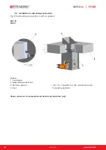
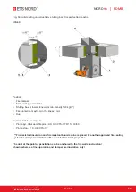
Страница 42: ...nstruction Fig 51 Solid ceiling construction mortar or gypsum EIS 120 EIS 90 Position 1 Fire damper 2 Solid ceiling construction 3 Mortar or gypsum min 110 Concrete min 125 Aerated concrete 4 Duct Around the perimeter Shown schemes of incorporation and damper are illustrative only ...

Страница 43: ... m 4 Fire protection mastic min thickness 1 mm 5 Duct Used materials example 3 Promapyr Rockwool Steprock HD Hilti CFS CT B 1S 140 50 4 Promastop P K Hilti CFS CT Fire resistant insulation and fire resistant board can be replaced by another approved fire sealing system for damper installation with equivalent material properties The duct at the point of penetration can be anchored to the fire wall ...

Страница 44: ... mm or 2xA 100 x B 100 mm Gap between damper and construction is filled by mortar or gypsum Distance between dampers 60 mm Flange to flange connection Up to 4 dampers can be installed Shown schemes of incorporation and damper are illustrative only The gap 94 mm between dampers can be filled by mineral stone wool min density 140 kg m Wool is fixed to damper body by fire protection mastic The gap 94...

Страница 45: ... mastic min thickness 1 mm 5 Cement lime plate min thickness 15 mm min density 870 kg m 6 Duct Used materials example 3 Promapyr Rockwool Steprock HD Hilti CFS CT B 1S 140 50 4 Promastop P K Hilti CFS CT Fire resistant insulation and fire resistant board can be replaced by another approved fire sealing system for damper installation with equivalent material properties The damper must be anchored t...

Страница 46: ...ng construction 3 Fire resistant board 4 Fire stop coating thickness 1 mm 5 Duct Used materials example 3 Hilti CFS CT B 1S 140 50 4 Hilti CFS CT Fire resistant insulation and fire resistant board can be replaced by another approved fire sealing system for damper installation with equivalent material properties Shown schemes of incorporation and damper are illustrative only ...

Страница 47: ...ed fire sealing system for damper installation with equivalent material properties Depends on the distance of the flap from the construction when the maximum distance from the construct is not limited and according to EN 15882 2 must use the required number of hinges according to EN 1366 1 2014 Reinforcement fixing VRM see Fig 81 Installation of profile U25x40x25 see Fig 82 When using Rockwool Con...

Страница 48: ...eiling construction Concrete EIS 90 Rebar steel wire Ø 6 mm Position min 110 Concrete min 125 Aerated concrete 1 Fire damper Around the perimeter 2 Solid ceiling construction 3 Concrete B20 4 Rebar 5 Duct Shown schemes of incorporation and damper are illustrative only ...

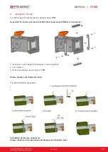
Страница 49: ...ant For lower resistance that EI90 the reinforcement VRM is not necessary 1 Insert part A B on body of fire damper in correct position 2 Lock screw C 3 It has to be done on each corner of VRM Shown dampers are illustrative only Fig 60 Installation procedure EIS 90 EIS 120 Installation details see chapter 9 4 Shown schemes of incorporation and damper are illustrative only ...

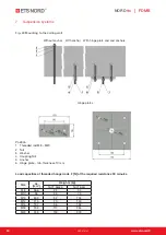
Страница 50: ...to the ceiling wall Position 1 Threaded rod M8 M20 2 Nut 3 Washer 4 Coupling Nut 5 Anchor 6 Hinge plate min thickness 10 mm Load capacities of threaded hanger rods F N at the required resistance 90 minutes Size As mm Weigh G kg for 1 piece for 1 pair M8 36 6 22 44 M10 58 35 70 M12 84 3 52 104 M14 115 70 140 M16 157 96 192 M18 192 117 234 M20 245 150 300 ...

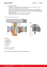
Страница 51: ... damper body is absolutely excluded Back to back air conditioning piping must be hung or supported so as all load transfer from the back to back piping to the damper is absolutely excluded Threaded rods longer than 1 5 m require fire resistant insulation Threaded rod fixing to the ceiling construction see fig 83 Fig 62 Suspension horizontal duct Position 1 Fire damper 2 Damping pad 3 Extension pie...

Страница 52: ... be hung or supported so as all load transfer from the back to back piping to the damper is absolutely excluded Threaded rods longer than 1 5 m require fire resistant insulation Threaded rod fixing to the ceiling construction see fig 83 Fig 63 Suspension vertical duct Actuating mechanism is placed above the ceiling construction Actuating mechanism is placed under the ceiling construction Position ...

Страница 53: ...olutely excluded Threaded rods longer than 1 5 m require fire resistant insulation If the threaded rod is located inside the duct insulation distance between threaded rod and duct is max 30 mm If the treaded rod is located outside the duct isolation distance between threaded rod and isolation is max 40 mm Thickness of the insulation under mounting profile must be min 30 mm Threaded rod fixing to t...

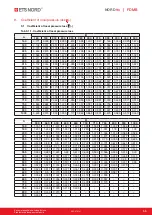
Страница 54: ...termination of pressure loss by using diagram 1 2 kg m Diagram 8 2 1 Pressure losses for air density 1 2 kg m p w 2 p Pa w m s kg m pressure lost air flow speed in nominal damper section air density coefficient of local pressure loss for the nominal damper section see Tab 11 1 1 IX Technical data ...

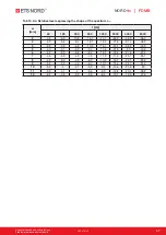
Страница 55: ...3 975 2 759 2 098 1 515 1 297 1 071 0 965 0 892 0 761 0 656 0 581 0 527 710 3 918 2 720 2 062 1 496 1 284 1 055 0 947 0 881 0 749 0 648 0 571 0 515 750 3 865 2 682 2 032 1 475 1 264 1 037 0 931 0 866 0 736 0 636 0 560 0 504 800 3 808 2 640 1 999 1 445 1 241 1 018 0 913 0 849 0 721 0 623 0 547 0 493 900 3 715 2 572 1 946 1 414 1 205 0 988 0 885 0 822 0 697 0 602 0 528 0 474 1000 3 643 2 519 1 904 1...

Страница 56: ...6 1 67 8 69 2 71 4 73 2 8 51 6 54 8 57 58 8 60 2 61 4 62 4 63 3 64 1 67 3 69 5 71 3 72 7 74 9 76 7 9 54 7 57 9 60 1 61 8 63 2 64 4 65 5 66 4 67 2 70 4 72 6 74 3 75 7 78 79 7 10 57 4 60 6 62 8 64 6 66 67 2 68 2 69 1 70 73 1 75 3 77 1 78 5 80 7 82 5 11 59 9 63 1 65 3 67 1 68 5 69 7 70 7 71 6 72 4 75 6 77 8 79 6 81 83 2 85 12 62 2 65 4 67 6 69 3 70 7 71 9 73 73 9 74 7 77 9 80 1 81 8 83 2 85 5 87 2 Ta...

Страница 57: ... 9 10 9 16 7 24 1 33 2 43 9 56 4 3 3 9 5 3 8 4 13 1 19 5 27 6 37 4 48 9 4 3 9 4 5 6 9 10 9 16 7 24 1 33 2 43 9 5 4 0 4 1 5 9 9 4 14 6 21 5 30 40 3 6 4 2 3 9 5 3 8 4 13 1 19 5 27 6 37 4 7 4 5 3 9 4 9 7 5 11 9 17 9 25 7 35 1 8 4 9 3 9 4 5 6 9 10 9 16 7 24 1 33 2 9 5 2 3 9 4 3 6 4 10 1 15 6 22 7 31 5 10 5 5 4 4 1 5 9 9 4 14 6 21 5 30 11 5 9 4 1 4 5 6 8 9 13 8 20 4 28 8 12 6 2 4 3 3 9 5 3 8 4 13 1 19 ...

Страница 58: ...ector pin with lever 4 Mechanical components entering the interior of damper body lower sheet of mechanics lock holder 1 lock lever 2 lock spring 8 dia stopper pin mechanics pin 5 Inspection hole cover including the clip and fasteners if they are parts of the cover 6 Bearing for torque transfer from the lever with pin on the angle selector at the leaf made from AISI 440C The leaf of the damper is ...

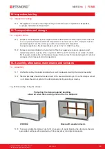
Страница 59: ...the range from 30 C to 40 C and maximum relative humidity 95 avoid condensation on the damper body Dampers must be protected against mechanic damages when transported and manipulated 14 Assembly 14 1 All effective safety standards and directives must be observed during fire damper assembly 14 2 The damper body should not be deformed in the course of bricking in Once the damper is built in its blad...

Страница 60: ... must be observed during fire damper assembly For regular or exceptional inspection of interior of fire damper micro camera device can be used On each fire damper is ispection hole In the case of inspection by camera take out the black rubber cap insert the camera inside the damper check interior and at the end of inspection put the rubber cap back tightly to cover the empty hole 15 2 Before enter...

Страница 61: ... required position Release of the locking mechanism can be achieved manually or automatically by applying the supply voltage 15 5 It is recommended to provide periodical checks maintenance and service actions on Fire Equipment by Authorized persons schooled by Producer 15 6 All effective safety standards and directives must be observed during fire damper assembly 15 7 Dampers could be displaced in...

Страница 62: ...tional digit Manual and thermal 01 Manual and thermal Zone 1 2 02 With actuating mechanism BF 230 TN BFL BFN 230 T voltage AC 230 V 40 With actuating mechanism BF 24 TN BFL BFN 24 T voltage AC DC 24 V 50 Manual and thermal with two terminal switches OPEN CLOSED 80 Manual and thermal with two terminal switches OPEN CLOSED Zone 1 2 81 Some designs are possible to supply with optical smoke detector O...

Страница 63: ...Kuvamateriaali on havainnollistava Pidätämme oikeuden muutoksiin RDT 07 0121 63 NORDfire FDMB 18 2 Data label is placed on the damper body IX Product data ...

Страница 64: ...ETS NORD Suomi Osoite Pakkasraitti 4 04360 Tuusula Finland Puh 358 0401 842 842 info etsnord fi www etsnord fi ...

Отзывы: