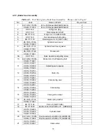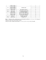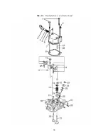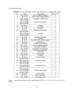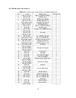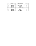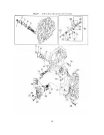
4-4 Fuel System Parts
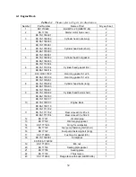
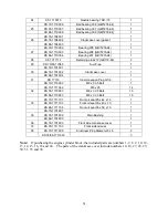
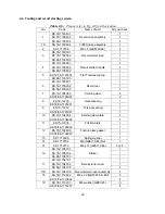
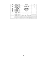
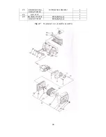
Table 4-4. Fuel system parts; please refer to Fig 4-4 for a complete illustration.
No.
Code
Name of part
Qty each set
1
KS 1710745
M8 x 45 (GB5787-86) Bolt
1
2
KS 17185
Upper fuel tank bracket fastener
1
3
KS 1710208
Flat washer 8 (GB97.1-85)
1
KS 70-1705801
1
KS 78-1705802
1
4
KS 86-1705803
Upper fuel tank bracket
1
5
KS 1705301
Injector
1
6
KS 17212
Hose Clamp
2
7
KS 17192
Fuel Pipe
1
8
KS 17184
Rubber fuel tank mount
4
KS 70-1704201
1
KS 78-1704202
1
9
KS 86-1704203
Fuel Tank
1
10
KS 17212
Fuel Pipe connectors
2
11
KS 17147
Fuel Pipe
1
12
KS 17151
M6 (GB6177-86) Fuel drain gasket
1
13
KS 17152
Fuel drain plug
1
14
KS 17183
Lower fuel tank bracket
1
15
KS 1710714
M6 x 14 (GB5787-86) Bolt
2
16
KS 1710106
M6 (GB6177-86) Nut
2
17
KS 1710206
M6 (GB97.1-85) Flat washer
1
18
KS 17150
Fuel tank cock assembly
1
19
KS 17154
Flat washer
1
20
KS 1719403
Fuel pipe clamp
2
21
KS 17189
Fuel pipe
1
22
KS 17148
Fuel filter gasket
1
KS 70-1704301
1
KS 78-1044302
1
23
KS 86-1704303
Fuel filter assembly
1
KS 70-1704702
1
KS 78-1704702
1
24
KS 86-1704700
Fuel injector pump
1
KS 70-1705601
1
KS 78-1705602
1
25
KS 86-1705603
High pressure fuel pipe
1
26
KS 17146
Fuel cup filter
1
27
KS 17153
Fuel cap assembly
1
28
KS 1705302
Fuel injector cap
1
Note:
The fuel tank assembly comes with numbers 9, 10, 11, 12, 13, 16, 17, 18, 19, 22, 23, 26
and 27.
39
Содержание 170F
Страница 1: ...OWNER S MANUAL AIR COOLED DIESEL ENGINE 170F FE FS FSE 178F FE FS FSE 186F FE FS FSE 1 ...
Страница 12: ...1 2 Diesel Engine shaft specifications units mm 12 ...
Страница 13: ...Sizes of PTO flanges Diesel Engine Power Curves 1 4 Names of Diesel Engine Parts 13 ...
Страница 20: ...20 ...
Страница 26: ...26 ...
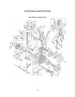
Страница 29: ...CHAPTER 4 PART LISTINGS Diesel Engine Exploded View 29 ...
Страница 32: ...Fig 4 1 Exploded view of engine block assembly 32 ...
Страница 35: ...Fig 4 2 Exploded view of cylinder head 35 ...
Страница 38: ...Fig 4 3 Exploded view of Piston Crank Assembly 38 ...
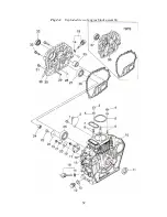
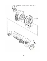
Страница 40: ...Fig 4 4 Exploded view of fuel tank parts 40 ...
Страница 43: ...Fig 4 5 Lubrication and speed control system 43 ...
Страница 46: ...Fig 4 6 Exploded view of cooling and recoil starting system 46 ...
Страница 49: ...49 ...
Страница 52: ...OWNER S MANUAL Air cooled diesel engine generator set DG4LE DG6LE 1 ...
Страница 59: ...8 1 4 Electric wiring diagrams for various models of generators Wiring diagrams for the LE models ...
Страница 60: ...9 ...
Страница 61: ...10 ...
Страница 71: ...20 ...
Страница 80: ...29 Figure 5 3 Exploded view of frame assembly ...
Страница 89: ...38 EASTERN TOOLS EQUIPMENT INC TEL 1 626 960 6299 FAX 1 626 960 6244 WEB SITE http easterntools com ...

