6
The control panel of a fire fighting booster is different
than the panel of a regular booster. Fire fighting
boosters are designed to work continuously during
a fire. Due to the law, these boosters do not include
thermal protection protecting the electrical engine
against fire.
Fire fighting boosters run only during fire. Thus,
there is a weekly test program aiming to minimize
the possible failures arising from long-term stand-by
and to detect and intervene to any available failure.
Fire fighting fighting booster works for a set period
of time automatically on a set date and time, and
stop. By ensuring the pumps operate one at a time
during the time set on the weekly test program, all
the pumps are operated in order.
If the water level falls below the minimum level in the
water tank, the device will not be able to supply the
required pressure and falls down to the calibration
set pressure (a value just below the operating
pressure). At this point, an audio and visual alarm
is activated. Thanks to the electronic circuit. If the
system demands water from the system during the
weekly test program, the test ends and the booster
starts working regularly.
15.2 Installation
• Install the fire fighting pump in a humid-free
environment without the risk of frost and
explosion, and good ventilation.
• To keep the temperature constantly above +4 °C
in the booster room or the booster station, the
appropriate environment and the tools should
be provided.
• The rooms should be large enough to allow
comfortable entry and exit.
• If the chamber is below the surface level, stairs
allowing easy entry and exit should be built.
(Because it is very important to intervene to the
failures in cases of emergency.)
• The room should be well illuminated and the
room should have a sufficient number of plugs.
• The fire fighting booster should be placed near
the water tank or cistern as close as possible. It
is required for the suction pipe to be short and
its diameter to be equal to or larger than the
diameter of the suction pump, and space should
ensure that the assembly will be made using a
minimum amount of curves or brackets.
• Pipe connections (collectors, suction line, delivery
line) should be arranged in a way that their inlets
and outlets do not prevent accessing the parts
required to be accessed during emergencies
and the control panels.,
• While placing the fire fighting boosters, it should
be considered that the engine and/or the pump
group may be required to be disassembled
and taken out of the room. (Pipe and collector
connections should not prevent dismounting
and removing the pump and/or engine that are
the other boiler room equipments.)
• The floor should be inclined enough to allow
water drainage. If the group chamber is below
the surface level, the accumulated water should
be discharged using submerged pump and the
submerged pump should be backed up.
• If there is a risk of flood in the chamber, electrical
control panels should be mounted as high as
possible. If required, it should be carried to a
section where there is no such risk.
• If the control panels are on the chassis of the pump
group, it should be ensured during assembly that
the control panel is easily accessible and its cover
is easily openable (for repair and maintenance).
• If the control panels are separate from the pump
group, it should be ensured during assembly
that the control panel is easily accessible and the
front panel is directly seen when entered into the
room.
• Control panels should be grounded.
16. Jockey Pump in a Booster Unit
The jockey pump in a booster set generally to
maintain the small amount of water demands in
death hours of a day instead of running the main
pump in a huge plant.
17. Maintenance
The booster sets do not require specific inspections
at regular intervals. As a precaution, however, we
recommend that you carry out some or all of the
following checks at varying intervals depending on
the operating conditions;
• Leaks
• Thermal protector activation
• No. of starts per hour
• Noisy operation
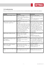
If any malfunctions are found, refer to the next
section for possible causes and remedies, Check
membrane tank air pressure regularly every 6
months (page 7). The pump does not require any
scheduled routine maintenance. It may require
extraordinary maintenance which is generally
cleaning the liquid end or replacing the mechanical
seal or other worn parts. In this case, please refer to
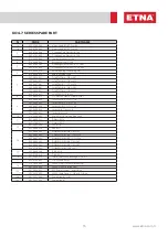
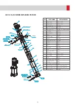
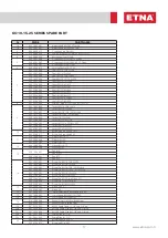
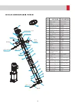
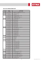
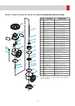
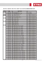
the pages 12 - 25.
Содержание EPH B-M46 Series
Страница 11: ...11 www etna com tr 22 Electric Panels for Single and Double Pump...
Страница 33: ...33 www etna com tr NOTES...
Страница 34: ...34 NOTES...
Страница 35: ...35 www etna com tr NOTES...


