5
www.etna.com.tr
10. Liquid Level Higher Than the Booster or
At The Same Level
Close the discharge valve, remove the fill/bleed plug and
open the suction valve until the water flows out of the fill/
bleed plug. Then close the plug.
11. Liquid Level Lower Than the Pump
(Negative Suction)
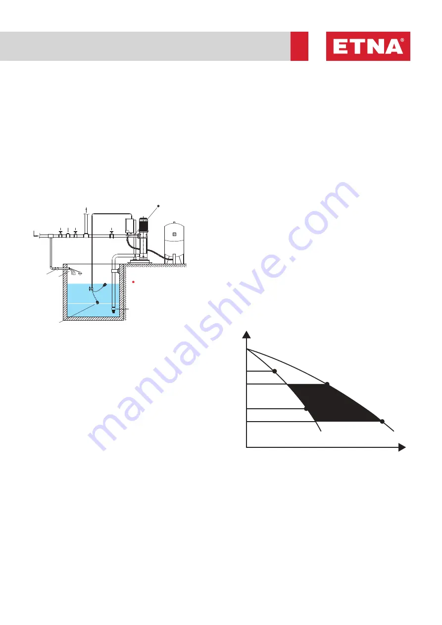
Close the discharge valve, remove the fill/bleed plug
and by means of a funnel fill the water, close the plug.
Note : Adjust the float switch according to the size of
the tank. (Page 9)
12. Checking the Rotation Three-Phase
Motors
After connecting and filling, start the pump with the
discharge valve closed and check that the rotation
direction is correct (shown on the coupling and the
motor) through the coupling protection or fan cover. If
the direction of rotation is not correct, stop the motor,
disconnect from the mains and invert two wires on the
terminal board. B
13. Operation
Start up the booster set with the discharge (delivery) gate
valve closed and fallow pump or pumps reaching to the
switched-off pressure of the unit from the manometer.
Then open the service tap and check the system pressure
is dropping and the pump or the pumps running at
the starting pressure. If everything is okay, open all the
gate valves in the delivery line and let the system under
booster-set pressure.
14. Operations Description
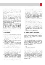
14.1 Example for two-pump sets
The starting and stopping of the pumps are determined
by the pressure values set on the pressure switches.
Each pressure switch is connected to a single pump
with a cyclic pump change over. The differential
pressure is the pressure difference between starting
pressure and switch-off pressure. It is set at the same
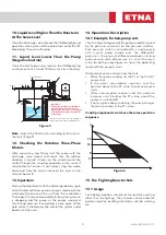
value for both pumps.Figure 6 shows the operating
mode with the pumps curves
On demand, water is drawn from the tank
• When the pressure drops to the P1 value the first
pump starts.
• If the water consumption increases and the
pressure drops to the P2 value, the second pump
starts.
• When consumption reduces and the pressure
increases until it reaches the P2s value, one of the
pumps is switched off.
• If consumption keeps reducing, the pump charges
the tank and stops at the P1s value.
3 and 4 pumps booster sets have the same operation
sequence
15. Fire Fighting Booster Sets
15.1 Usage
Fire fighting boosters should not be used for anything
other than fire-fighting. They should not be used for
garden irrigation, building installation, vehicle washing
etc.
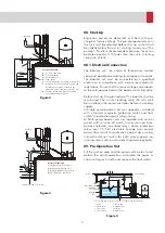
1 - Valve
2- Check valve
3- Float valve
4- Float switch
5- Service tap
6- Upright valve
7- Strainer
8- Water Tank
1
1
2
2
5
3
4
* The suction pipe should be at least 15 cm above the tank bottom.
*
To the building
Mains
Operating level
Stoppage
Level
Starting-Stop
Level Setting
7
8
Important:
Check valve should not be installed on
the delivery line of the booster sets
with negative suction level. The upright
valve installed on suction also acts like
a check valve.
# A check valve should not be installed on
the delivery line of the plumbing either.
To the building
1
1
2
Mains
6
1
3
4
7
P1s
H
P2s
P1
P2
Figure 5
Figure 6
Содержание EPH B-M46 Series
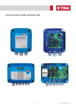
Страница 11: ...11 www etna com tr 22 Electric Panels for Single and Double Pump...
Страница 33: ...33 www etna com tr NOTES...
Страница 34: ...34 NOTES...
Страница 35: ...35 www etna com tr NOTES...


