XETK-V2.0 - User’s Guide
29
ETAS
Hardware Description
4.8.3
Data Emulation Power Failures
The XETK-V2.0 has a circuit which recognizes and stores power failures. The
XETK-V2.0 will notify the microcontroller software of the power failure using the
DAI pins and additionally will prevent the user from switching to the working
page until the PC software has downloaded a new Working Page data into the
data emulation memory.
The calibration feature "start on working page" or "start on last active page
with the last active page being the working page" is only possible when the
working page has been downloaded since the last power failure. Until a down-
load occurs after a power failure the microcontroller software is informed of a
power failure by the DAI pins and is responsible to make the reference page
active.
4.9
Nexus (JTAG) Interface
4.9.1
XETK-V2.0A/C
Microcontroller
(VertiCal Base Board)
TDO
TDO
/RDY
/RDY
/TRST
TDI
R >=100k
or Pullup
TDI
/TRST
TMS
TCK
TMS
1k
1k
TCK
ECU
XETK
22
22
22
22
1k
V_NEXUS
XETK
System
Controller
MDO[15..0]
/MSEO[1..0]
/EVTO
MDO[15..0]
/MSEO[1..0]
/EVTO
/EVTI
/EVTI
22
MCKO
MCKO
VertiCal
Connector
Other ECU
JTAG / Nexus
Connectors
not present
not present
not present
not present
not present
not present
not present
not present
not present
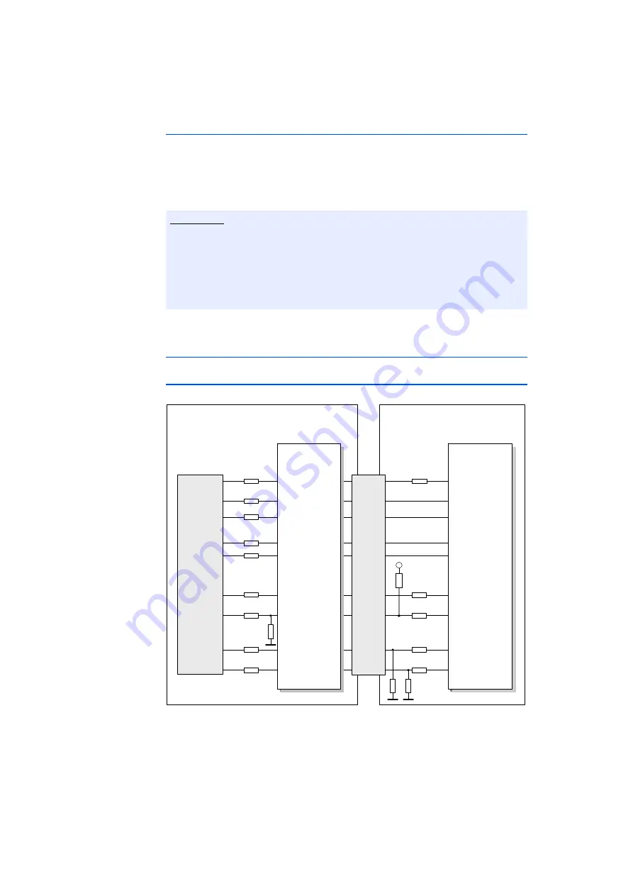
Fig. 4-12
Equivalent Circuitry of the XETK-V2.0A/C Nexus (JTAG) Interface
The ECU part of the XETK-V2.0A/C Nexus (JTAG) interface is depicted in
Fig. 4-12. The XETK incorporates 22 Ohm series resistors for the TDI, /TRST, TCK,
and TMS lines on the ECU interface. Additional pull ups / downs are as shown.
Note


