


2. A
SSEMBLY
PROCEDURE
Open the box, and take out the tools: cross screw driver and spanner.
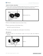
Check the setting on the voltage selector located on the bottom of the power box according to local
network voltage.
We provide two voltage options: 220V / 110V.
A F1AL250V fuse has been inserted into the power box. Spare fuse are provided in the box.
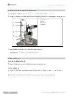
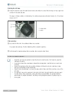
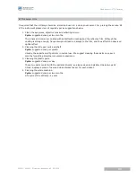
Remove "A team" screws (4*M6 x20mm) under the tabletop.
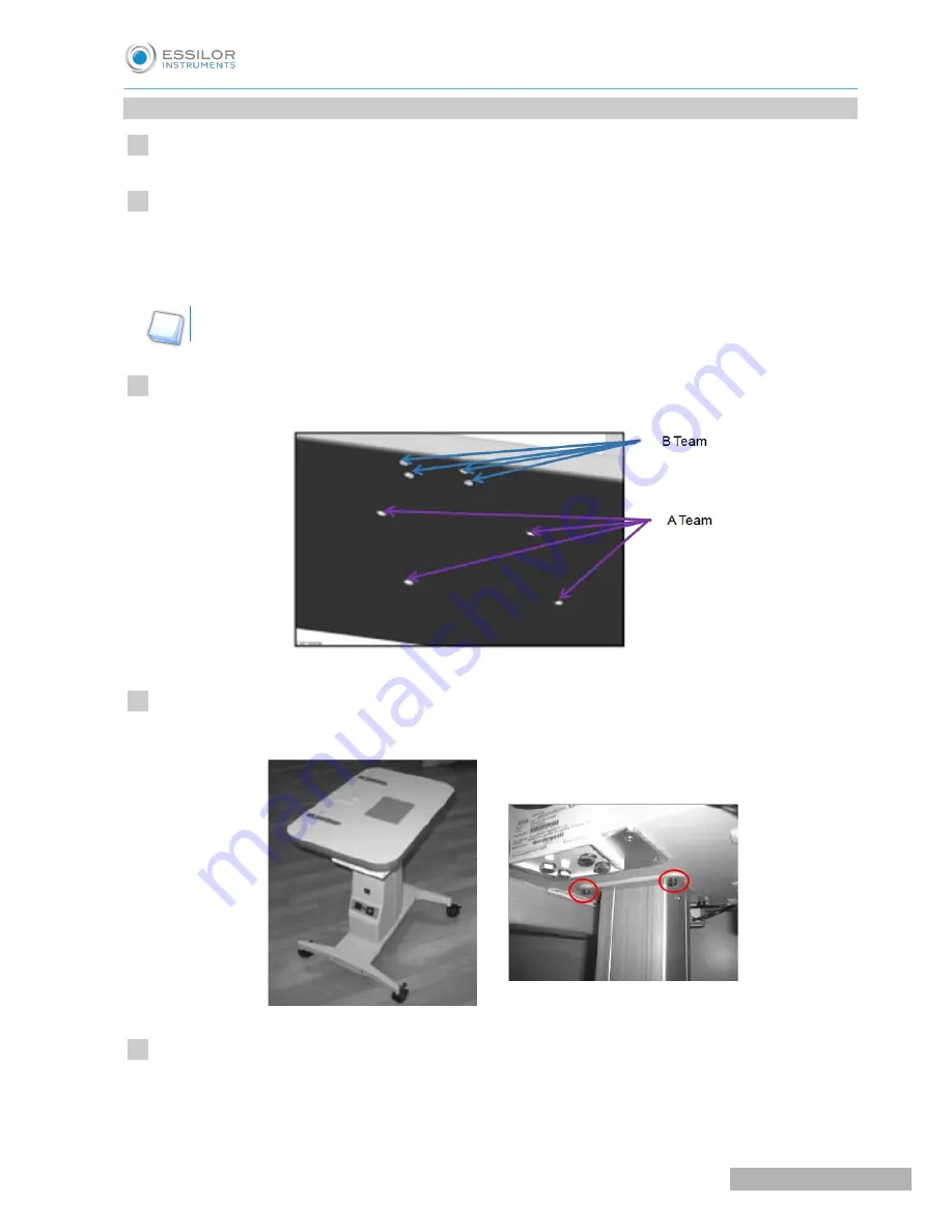
Lift the tabletop to align its screw holes to the assembly holes of the instrument table and fix the
tabletop with the power switch facing to the operator.
Connect two white adapters under table board.
Turn ON and press "Up & Down" switch to check whether the power table works well.
1
2
3
4
5
U
SER
MANUAL
> IV. A
SSEMBLY
21
SL300L / SL400L - Slit lamp microscope > V2 - 03-2018
Содержание SL 300
Страница 1: ...www essilor instruments com User manual...
Страница 4: ...I INTRODUCTION...
Страница 8: ...II SAFETY AND PRECAUTIONS...
Страница 13: ...III NOMENCLATURE...
Страница 16: ...IV ASSEMBLY...
Страница 24: ...V OPERATION PROCEDURES...
Страница 30: ...VI CLEANING...
Страница 33: ...VII MAINTENANCE...
Страница 36: ...VIII TROUBLESHOOTING GUIDE...
Страница 38: ...IX APPENDIX...
Страница 39: ...Electrical circle drawing SL300L SL400L Slit lamp microscope V2 03 2018 44 USER MANUAL IX APPENDIX...


