background image

Installing Special Equipment 


14 


Care@Home™ Passive Infrared Detector User Guide 


2.


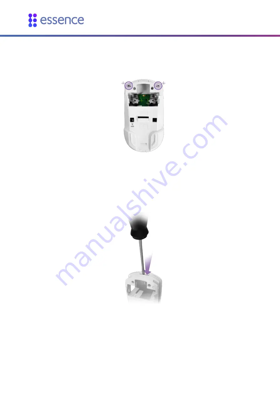
If there are screws in the back cover, unscrew the two screws above the battery compartment at 
the top of the back cover, as shown in Figure 10 below. 


Figure 10: Unscrew the Screws 

3.


Holding the back cover upright, insert a flat screwdriver between the lock tab of the front panel 
and the top of the back cover, as shown in Figure 11 below, pushing downward on the inner latch 
tab, to release the back cover from the front panel. 


Figure 11: Back Cover Latch Tab under Front Panel Lock Tab 

4.


Detach the back cover from the front panel. 

Figure 12 below shows the front panel and the back cover of the PIR. 

Содержание Care@Home ES700PIR

Страница 1: ...Care Home Passive Infrared Detector User Guide ESUGSC008 Version 1 0 September 2015...

Страница 2: ...bove disclaimers exclusions or limitations may not apply to you By using the information contained herein you agree that the laws of the State of Israel without regard to principles of conflict of law...

Страница 3: ...Opening the PIR 13 4 1 2 Closing the PIR 15 4 2 Pet Immune Lens 16 4 3 Optical Limiter 18 5 Operation 21 5 1 PIR Physical Attributes 21 5 2 Notifications 21 5 3 Supervision 22 6 Maintenance 23 6 1 Re...

Страница 4: ...ptics with insect immunity Daylight immunity White ESI 4th Generation DragonflyEye Multi Zone spherical lens A mounting base with mounting double sided adhesive tape Figure 1 Essence Passive Infrared...

Страница 5: ...ing when selecting a mounting location for the PIR A flat wall surface or a corner in a room A surface that is clean dry and smooth Within 700 m 2296 ft of the CP open air nominal A coverage area with...

Страница 6: ...ned bathroom see section 4 3 on page 18 2 3 Best Practices When installing the Pro or Family systems the PIR should be installed in accordance with the following guidelines Avoid overlapping coverage...

Страница 7: ...to the couch and if possible not opposite the dining room Install the dining room PIR diagonal to the dining room table and if possible not facing the living room Install the lavatory PIR 30 50 cm 1...

Страница 8: ...n instructions see chapter 4 on page 13 This chapter defines the Standard installation process Testing the installation 3 1 Installing the PIR To install the PIR perform the following procedure 1 Iden...

Страница 9: ...installing the special equipment see chapter 4 on page 13 6 If the PIR is not from the Care Home kit add the PIR to the Care Home system by pairing the PIR with the CP Press the PAIRING button located...

Страница 10: ...up Red indicating that the PIR has powered up successfully Figure 7 LED Indicator WARNING A new battery can explode if it is incorrectly installed Discard used batteries responsibly Remember To compl...

Страница 11: ...onal peripheral devices can be integrated as when the CP memory is full the CP beeps and the ring lights up Red The CP returns to its previous operation mode automatically following the pairing proces...

Страница 12: ...is used to determine the detection area of the PIR The Walk Test mode starts automatically after the PIR powers up such as When a new battery is inserted After adding and pairing a new PIR with the C...

Страница 13: ...ignore the pet s movements The following equipment installed in the PIR can solve these situations Pet Immune Lens Optical Limiter 4 1 Open and Close the PIR To install the special equipment you must...

Страница 14: ...10 Unscrew the Screws 3 Holding the back cover upright insert a flat screwdriver between the lock tab of the front panel and the top of the back cover as shown in Figure 11 below pushing downward on t...

Страница 15: ...op of the back cover onto the top of the front cover while aligning the latch tab under the lock tab of the front panel as shown in Figure 11 on page 14 3 Holding the PIR with the back cover facing yo...

Страница 16: ...is not recommended to install the Pet Immune Lens in a PIR that includes an Optical Limiter The coverage area of the PIR may be further reduced To install the pet immune lens in the PIR perform the fo...

Страница 17: ...lens is not released insert a dull thin object through the oval opening and gently push the outer lens and release it as illustrated in Figure 16 below Figure 16 Back Cover Oval Opening 4 Insert the...

Страница 18: ...latch tabs hold both lenses in place Figure 18 Lens Tabs for PIR Lens Insertion 6 Close the PIR according to the instructions in section 4 1 2 on page 15 4 3 Optical Limiter In a combined bathroom the...

Страница 19: ...installation height Table 1 Coverage Area for PIR with Optical Limiter Installation Height Coverage Area Radius 2 0 m 0 50 m 1 8 m 0 45 m 2 2 m 0 55 m For installation in a combined bathroom first ins...

Страница 20: ...into place as shown in Figure 22 below Otherwise the PIR cannot close properly Figure 22 Optical Limiter installed in PIR 4 Close the PIR according to the instructions in section 4 1 2 on page 15 5 In...

Страница 21: ...cted or a tamper event occurs 5 2 Notifications The PIR sends notifications to the CP for the following events A motion detection event The room temperature on the premises passes the configured tempe...

Страница 22: ...nstalled on your Resident s premises 5 3 Supervision The PIR is a supervised device The PIR periodically transmits its status via an I m alive message to the CP The frequency of the reporting periods...

Страница 23: ...battery must be replaced WARNING A new battery can explode if it is incorrectly installed Be careful to replace the battery only with the same or equivalent type recommended by the manufacturer Discar...

Страница 24: ...elease of residual circuit or energy The rattling sound is the internal tamper prevention mechanism No damage has occurred to the PIR 5 Insert the new battery as illustrated in Figure 6 on page 10 NOT...

Страница 25: ...ical lens 12 m detection range 105 horizontal 80 vertical 102 zones 6 vertical beams Daylight Immunity Electrical Power Supply 1 x 3V CR123A Lithium Battery manufactured by GP with a battery capacity...

Страница 26: ...r power up 10 minutes Visual Indications 1 LED for Detection Tampering Walk Test Environmental RFI Protection Over 30V m Operating Temperatures 0 49 C 32 120 2 F Storage Temperatures 20 60 C 4 140 F P...

Страница 27: ...thod consider the following Installation with the mounting tape is more common The screws on the right side of the inside of the mounting base covering the punch out holes on the left side of the PIR...

Страница 28: ...Cover The PIR can be installed using mounting tape The mounting tape is approved for the following surfaces ABS Polycarbonate PC Aluminum Galvanized Steel Enameled Steel Stainless Steel Nickel Coated...

Страница 29: ...n angle facing to the right On an angle facing to the left In a corner The thin plastic covering over the holes can be removed if necessary All the corner support holes are blocked by the mounting tap...

Страница 30: ...d in Figure 4 on page 8 2 For wall mounting Use a flat screwdriver to remove the punch outs 1 and 2 as shown in Figure 29 above a Clean the surface where the PIR is to be installed b Place and hold th...

Страница 31: ...t server side script engine for dynamically generated web pages CP An Essence Term Control Panel DIY Do It Yourself DMZ Demilitarized Zone In computer security a DMZ is a physical or logical sub netwo...

Страница 32: ...using radio signals to transfer data from a tag attached to an object for automatic identification RIA Rich Internet Application Web application with many characteristics of desktop application softwa...

Страница 33: ...zed set of methods and a network protocol to allow an end host to discover its public IP address if it is located behind a NAT STUN is used to permit NAT traversal for applications of real time voice...

Страница 34: ...ation digital rights management functionality contained in the Application 3 use the Application to access copy transfer or retransmit content in violation of any law or third party rights or 4 remove...

Страница 35: ...odes and lock outs c The Application is designed to utilize your enabled cellular Device to access the System The Device will work only in areas where the cellular service has coverage and Company has...

Страница 36: ...may present links in a format that enables us to keep track of whether these links have been followed Third Party Sites This Privacy Policy applies only to the Application functionality on the System...

Страница 37: ...cate upon activation Notwithstanding the forgoing Company shall not be responsible for loss of System connectivity or data due to cellular network disconnections The System must be used as intended an...

Страница 38: ...evices used for access are lost or accessed by others and Company shall have no liability for such third party unauthorized access 3 The System will work only in areas where the cellular service has c...

Страница 39: ...ored and or photographed and or recorded without their knowledge and prior authorization 1 Security We are concerned with safeguarding your information We employ a variety of safety measures designed...

Отзывы: