!
2. PCB Layout Design
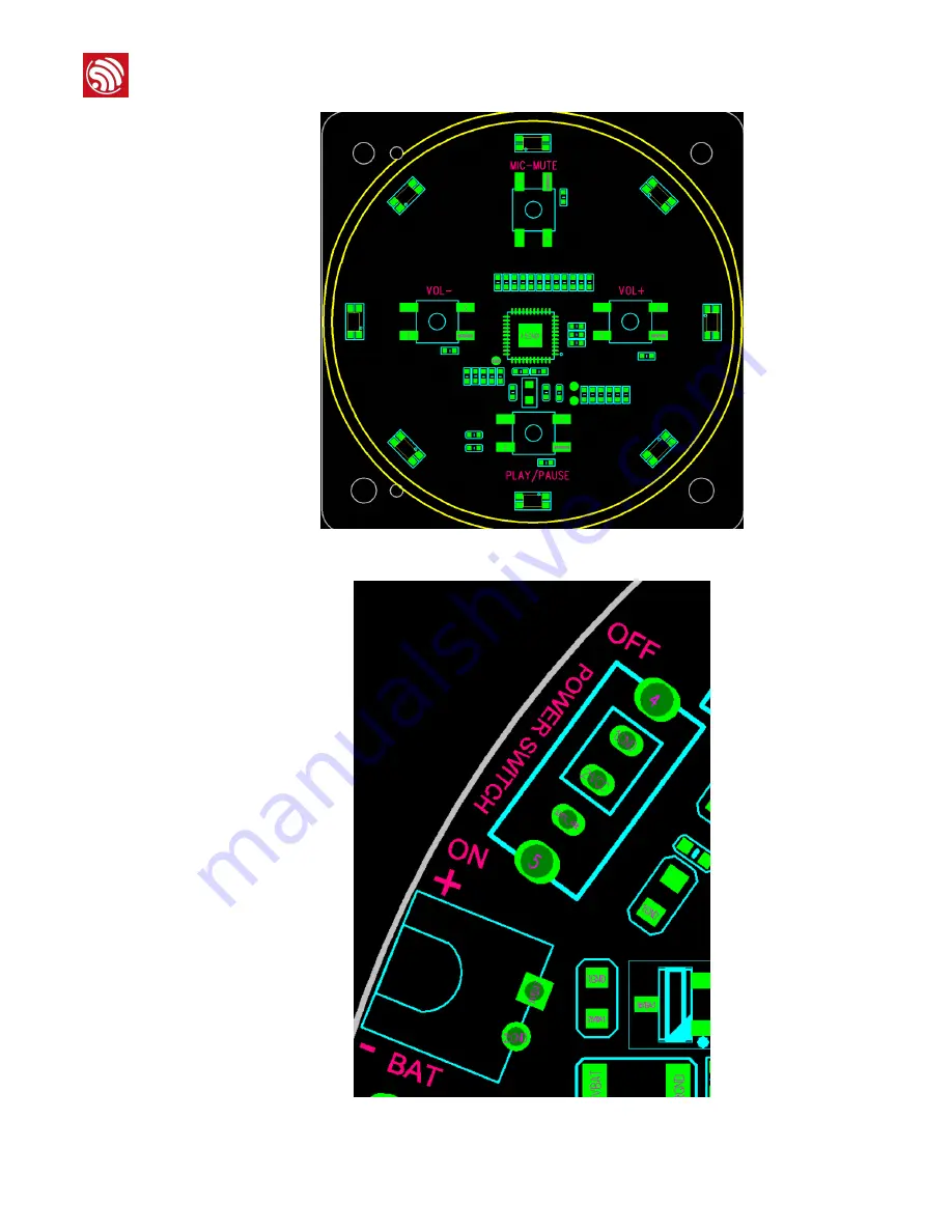
Figure 2-6. Positioning Plug-in Components
Figure 2-7. Positioning Plug-in Components
Espressif
/19
12
2019.01
Страница 1: ...www espressif com ESP32 Audio Design Guidelines Version 1 0 Espressif Systems Copyright 2019 ...
Страница 2: ...tion Change Notification Espressif provides email notifications to keep customers updated on changes to technical documentation Please subscribe at https www espressif com en subscribe Certification Download certificates for Espressif products from https www espressif com en certificates Date Version Release notes 2019 01 V1 0 Initial release ...
Страница 3: ...y Pins 4 1 3 4 Dedicated Pins 5 1 3 5 Strapping Pins and Other Special Pins 6 2 PCB Layout Design 8 2 1 General Principles of PCB Layout 8 2 1 1 PCB Layers 8 2 1 2 General Guidelines for Routing Traces 8 2 2 Key Points of PCB Layout Design 9 2 2 1 Positioning an ESP32 Module on a Baseboard 9 2 2 2 Positioning Plug in Components 11 2 2 3 Positioning Chip Components 13 2 3 Power Traces Ground Traces...
Страница 4: ...s supplying current of the nominal value identified in its specification but if the battery is not detected the output current is very small and power supply for the circuit may be insufficient You can avoid this problem by adding a USB Battery power supply switch circuit into the design as shown in Figure 1 1 For example if a USB cable is plugged in VBAT pin is cut off from the system and the pow...
Страница 5: ...other aspects of the circuit For example Figure 1 2 Power Supply Management Circuit for Peripherals 1 1 3 Ground Plane Splitting Scheme For the above listed modules Wi Fi module Codec module DSP module PA power amplifier module Micro SD card module LED module etc their reference ground planes should be separated according to the actual situation For example the reference ground plane of Wi Fi modu...
Страница 6: ... processors DSP might require different reference ground planes Some PA power amplifiers can support differential inputs while others support only single ended input etc For example The specific design rules for a DSP Figure 1 4 Reference Circuit Design for a DSP Ground Plane The separation of AGND and DGND for a Codec Note In your design you need to refer to the datasheet or reference design of t...
Страница 7: ...ly recommended on CHIP_EN pin to form an RC delay circuit to avoid level instability on CHIP_EN end in power on process In addition CHIP_EN serves as the reset pin so it is recommended to connect it to a button for the reset operation 1 3 3 Input only Pins Some pins of ESP32 can be used for input only such as CHIP_EN SENSOR_VP SENSOR_CAPP SENSOR_CAPN SENSOR_VN IO34 IO35 etc For example Note SENSOR...
Страница 8: ...MD SCK CLK SDO SD0 SDI SD1 IO15 IO5 Button_Array_ADC SENSOR_VP EN EN ESP_VDD33 DGND DGND DGND ESP_VDD33 DGND ESP32 Module Close to Module C8 0 1uF 16V 10 R162 0R 5 U9 ESP32 WROOM 32D GND1 1 3V3 2 EN 3 SENSOR_VP 4 SENSOR_VN 5 IO34 6 IO35 7 IO32 8 IO33 9 IO25 10 IO26 11 IO27 12 IO14 13 IO12 14 GND3 38 IO23 37 IO22 36 TXD0 35 RXD0 34 IO21 33 NC 32 IO19 31 IO18 30 IO5 29 IO17 28 IO16 27 IO4 26 IO0 25 ...
Страница 9: ...other chips such as MCLK master clock so using GPIO0 for other functions is not recommended GPIO2 is another strapping pin and its level state in the power on reset process is also related to download 0 enter download mode and the chip defaults to 0 Meanwhile GPIO2 can be used for connection to SDIO MMC for example SD card so using GPIO2 for other purposes is not recommended For example Note In yo...
Страница 10: ... as the pin to connect JTAG Therefore it is not recommended to use GPIO12 for other purposes Please pay particular attention to the fact that the level state in the power on reset process of GPIO12 cannot conflict with the output voltage of LDO Pins used as ADC DAC TouchPad SD card JTAG RTC domain pins required in low power sleep mode etc are all special pins Please refer to ESP32 Datasheet while ...
Страница 11: ...eral Guidelines for Routing Traces General guidelines for routing traces are as follows Try to plan out the shortest route and pass through the least holes avoid unnecessary bending and holes Use obtuse angles to keep the layout as clean and tidy as possible avoid using right angles and acute angles or hiding small line segments among these angles Avoid routing traces on the layers under crystal o...
Страница 12: ...2 Key Points of PCB Layout Design 2 2 1 Positioning an ESP32 Module on a Baseboard Place the module s PCB antenna area outside the baseboard but put the module as close to the edge of the baseboard as possible so that the antenna s feed point is closest to the board edge For example Espressif 19 9 2019 01 ...
Страница 13: ...e 2 4 Clearance Zone for ESP32 Module s Antenna on the Baseboard The module s antenna area should be as far away from other parts as possible especially from the audio output The antenna area is recommended to be in the opposite direction of the audio output or at least at 90 degrees if the former cannot be satisfied For example Note As shown in Figure 2 3 the recommended position for an ESP32 mod...
Страница 14: ...positioning of their components should adhere to the following principles Taking component structures into account trying to make mounting connecting easy Facilitating the actual debugging operation Assisting trace routing For example Note In particular you need to pay special attention to plug in direction pin sequence positive and negative polarity of these components It is recommended to label ...
Страница 15: ... 2 PCB Layout Design Figure 2 6 Positioning Plug in Components Figure 2 7 Positioning Plug in Components Espressif 19 12 2019 01 ...
Страница 16: ...nly Please make sure you have a filter capacitor near each power pin but do not stack all the capacitors in one place For the sake of routing and ground splitting modules sharing the same ground plane should be placed near as well as the functionally related modules Codec PA power amplifier and speaker of Audio chip as well as USB interface charging module and battery interface See the picture bel...
Страница 17: ...through layers should meet the requirements of current flowing Traces of 1 mm wide should be able to carry the current of up to 1 A A 0 25 mm via on a 0 5 mm pad should be able to carry the current of up to 500 mA If copper foil is laid please make sure that the width of each power trace is constant along their length with no bottlenecks due to other traces or vias Espressif 19 14 2019 01 ...
Страница 18: ...Recommended Power Routing 2 3 2 Ground Traces Routing Different reference ground planes should be separated Please keep the cutting lines consistent on all layers and drill more ground holes around the 0R resistors that connect the reference grounds It is also recommended to drill as many ground holes as possible close to the devices GND pins especially in the area of the power supply s filter cap...
Страница 19: ... 2 PCB Layout Design Figure 2 11 Reference Design for Ground Trace Routing Figure 2 11 Reference Design for Ground Trace Routing Espressif 19 16 2019 01 ...
Страница 20: ...ing to different groups The signal traces for Reset should be as short as possible and isolated from other traces by ground traces or by extending the distance to reduce interference The signal traces for audio input and output need to be enclosed with ground traces and surrounded by more ground holes for shielding TouchPad trace routing must be done in accordance with the relevant guidelines to a...
Страница 21: ... 2 PCB Layout Design Figure 2 15 Reference Design for Audio Signal Trace Routing Figure 2 16 Reference Design for TouchPad Traces Routing Espressif 19 18 2019 01 ...
Страница 22: ...ility for infringement of any proprietary rights relating to use of information in this document is disclaimed No licenses express or implied by estoppel or otherwise to any intellectual property rights are granted herein The Wi Fi Alliance Member logo is a trademark of the Wi Fi Alliance The Bluetooth logo is a registered trademark of Bluetooth SIG All trade names trademarks and registered tradem...