Type / No.
Rev.
Date
Page
Total pages
EW082.695_en
5
02 August 2010
22
28
EsiWelma
s.r.l.
4.9
Sensor operation check
After the sensor is calibrated it is necessary to make sure it is operating correctly. For this
purpose, it is necessary to scrupulously perform the following in order to prevent incorrect
test actions that could cause permanent damage to the sensing element.
We recommend using the TUL40 calibration and test case for this purpose. It consists of:
•
One cylinder (12 l) of gas calibrated at 50% of the L.E.L. of the detected gas (e.g.:
Methane)
•
One pressure valve and flow regulator (the latter is optional)
•
One flow chamber that will fit properly around the sensing element
•
One hose between cylinder and adapter (
∼
2 m long)
In any case, follow the checklist below to carry out the test:
1.
for the test, use the same type of gas that the sensors will be detecting
2.
the test cylinder must be calibrated with the concentration kept below the maximum
levels of the detector measuring range
3.
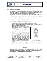
the test gas flow must spread to the sensing
element or reach it at a low flow rate (max 0.5
litres / minute).
For
this
purpose,
use
a
specific
flow
measurement chamber that fits properly around
the sensing element (Fig. 4.26), and if necessary
a field flow meter
4.
a few dozen seconds may pass from the time the
test gas is released to the moment the detector
senses its presence and precisely measures its
concentration. This “delay” is caused by the
action of the sintered filter located at the bottom
end of the detector to protect the sensing
element. The same delay may occur from the
moment test gas release is terminated until the
moment the detector no longer senses its
presence.
5.
the sensor must activate the alarm during the test: make sure the alarm is activated
by controlling the LED status on the sensing element; this must be flashing as shown
in table 4.2, according to the concentration level detected by the TUS40-20 terminal
unit in the monitoring mode described above.
WARNING
Repeated use of inappropriate or high concentrations of test gases causes
permanent poisoning of the sensing element with a subsequent deterioration in
performance, or permanent abnormality, of the detector.
Test gas inlet
Test gas outlet
F
lo
w
c
h
a
m
b
e
r
Fig. 4.26 – Flow chamber


