background image


Type / No. 

Rev. 

Date 

Page 

Total pages 

EW082.695_en 

02 August 2010 

20


28 


EsiWelma

 s.r.l.


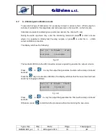
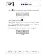
Press  the                key  to  memorise  calibration;  the  display  will  show  the  previous  display  as 
confirmation that the new value has been saved: 


To terminate the procedure press key           . 
 
The  warm-up  phase  is  suspended  during  4...20mA  calibration  test  mode  and  starts  again 
after returning to monitoring mode. 
 
If  no  key  is  pressed  for  5  minutes  during  4...20mA  output  calibration  mode,  it  automatically 
exits from the calibration mode and returns to monitoring mode. 
 
 
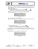
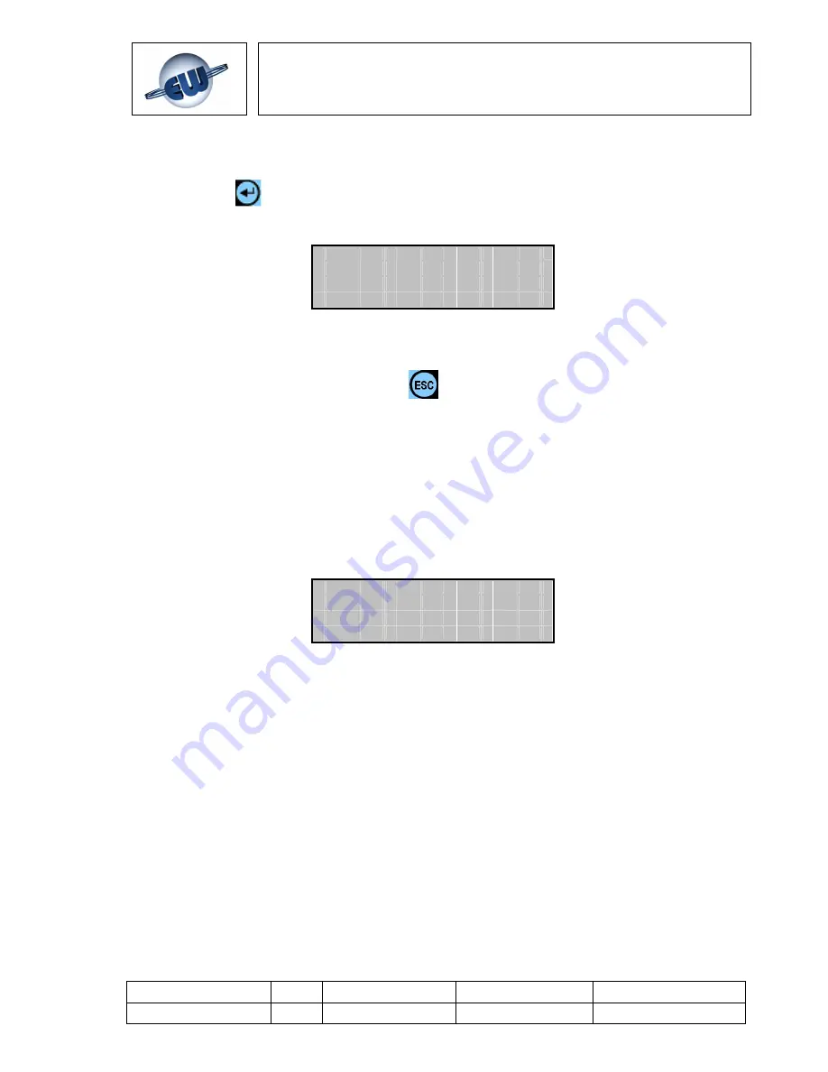
The device is automatically reset in all output modes, as shown in the following display: 


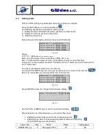
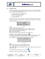
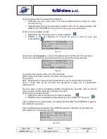
C  a  l  i  b  .    4  -  2  0  m A :       4  m A  


4  =  X  X  X  X        1  5  =  X  X  X  X     


Fig. 4.23


  *    R E  S  E  T    -    W A I  T    *   


Fig. 4.24 


Содержание TUS40-20

Страница 1: ...Type No Rev Date Page Total pages EW082 695_en 5 02 August 2010 1 28 EsiWelma s r l HANDHELD TERMINAL FOR MONITORING AND SETTING UR 20 SENSORS Terminal Unit TUS40 20 INSTRUCTION MANUAL...

Страница 2: ...INAL UNIT 8 3 2 TYPES OF DETECTOR INSTALLATION FOR CORRECT MONITORING 10 4 USING THE TERMINAL UNIT 11 4 1 OPERATING MODES 11 4 2 MONITORING MODE 12 4 3 SETTING MODE 13 4 4 CALIBRATION MODE 14 4 5 CALI...

Страница 3: ...rs the hazardous conditions begin from a threshold called Lower Explosive Limit LEL that is the lowest concentration percentage of a gas in air capable of producing a flash of fire in presence of an i...

Страница 4: ...usea loss of movement in hands 30 40 Strong headache irritability confusion loss of vision nausea muscle weakness dizziness 40 50 Convulsions and loss of consciousness 60 70 Coma respiratory arrest de...

Страница 5: ...essary when a mobile monitoring system is required and or for different settings of the gas detection threshold limit values from the ones that can be set using the DIP switch it is also necessary for...

Страница 6: ...20 E Group II Category 3G Ex nA d IIC T6 TAMB 20 C 50 C UR 20 S Unclassified non hazardous areas ATEX certification is not required Heavy duty applications Construction conforming to Ex d requirements...

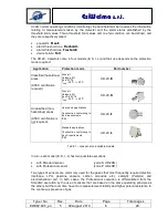
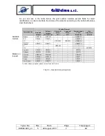
Страница 7: ...s Sensing Element Standard Catalytic Pellistor Catalytic Professional 2 terminal Electr Cell Standard 3 terminal Electr Cell Professional Semiconductor 1 or 2 thresholds applications Non Dispersive in...

Страница 8: ...1 Make sure the area is clear of gas and that the sensor is not powered up 2 Open the UR 20 sensor cover Fig 3 1 3 Identify the position of the CN4 connector on the diagram Fig 3 2 4 Plug the junction...

Страница 9: ...ust 2010 9 28 EsiWelma s r l CN4 connection Fig 3 2 CN4 position Fig 3 3 TUS40 terminal plug in operation Warning Properly align the female and male CN4 connector with the PCB side of the UIC20 juncti...

Страница 10: ...tretched to its full length when it is plugged in to make sure it does not disconnect from the junction card Do not use extension cords on the cables and do not extend the cables themselves by cutting...

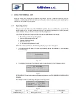
Страница 11: ...TUS40 20 terminal unit can be used for several calibrations and checks Monitoring or normal operating mode Alarm thresholds setting mode Sensor calibration mode Output test mode 4 20mA signal calibra...

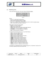
Страница 12: ...any kind is detected The abbreviation identifying the sensor is one of the following CAT_1 for type A catalytic sensors CAT_2 for type B catalytic sensors CAT_3 for type C catalytic sensors CEL_4 for...

Страница 13: ...2 is the 1 st alarm level and Threshold 3 is the 2nd alarm level The cursor an asterisk starts out on the first line Use the UP and DOWN keys to scroll up to the previous line or down to the next line...

Страница 14: ...XXXXX Value in steps of the A D converter of the 2 nd calibration set point ZZZ Units of the concentration PPM or LEL KKK Value of concentration SSSS Steps of the A D converter equivalent to the measu...

Страница 15: ...the following screen in Figure 4 12 From this menu by press the 1 button it can be execute the reset upon confirmation of the calibration values to those inserted by the manufacturer of the sensor Pr...

Страница 16: ...ent The next line SSS Steps applied to the electronic potentiometer only for sensors that include this VVVV Value read by the converter and expressed in steps not in concentration measuring unit The t...

Страница 17: ...cessful where VVVV Values read by the converter and expressed in steps at point 0 and at the 2nd point Or At this point it is possible to press ESCAPE to take the sensor back to normal operation ENTER...

Страница 18: ...the alarm relay output for exceeding the 2nd threshold 3 To activate and deactivate the alarm relay output for exceeding the 1st threshold 4 To activate and deactivate the pre alarm relay output To in...

Страница 19: ...directly test the relay outputs or press 0 to enter the 4 20mA output calibration procedure The display will show the following The two fields XXXX are the A D Converter values required to generate th...

Страница 20: ...key The warm up phase is suspended during 4 20mA calibration test mode and starts again after returning to monitoring mode If no key is pressed for 5 minutes during 4 20mA output calibration mode it...

Страница 21: ...Table 4 1 Diagnosis of possible causes of fail Some error sequences are reported by particular flashing in the visual alarms present on the UR 20 detector For a complete table of sensor fail reporting...

Страница 22: ...sensing element or reach it at a low flow rate max 0 5 litres minute For this purpose use a specific flow measurement chamber that fits properly around the sensing element Fig 4 26 and if necessary a...

Страница 23: ...ero the sign becomes negative and the system continues to operate and count down the weeks of operational lifetime but of course there is no guarantee that the sensor is operating correctly 4 11 Chang...

Страница 24: ...staller s stamp and signature Installation site and or room Product order number Part Number Manufacturing date DETECTORS No Gas detected Position of detector No Gas detected Position of detector 1 26...

Страница 25: ...Type No Rev Date Page Total pages EW082 695_en 5 02 August 2010 25 28 EsiWelma s r l 6 ROUTINE CHECKS To be filled in by Installer Service Personnel Signature Date Description...

Страница 26: ...Type No Rev Date Page Total pages EW082 695_en 5 02 August 2010 26 28 EsiWelma s r l NOTES...

Страница 27: ...Type No Rev Date Page Total pages EW082 695_en 5 02 August 2010 27 28 EsiWelma s r l...

Страница 28: ...Via F lli Canepa 134D E 16010 Serra Ricc Genova Italy Tel 39 010 75421 1 Fax 39 010 75421 78 e mail info esiwelma it Web www esiwelma it EsiWelma s r l...

Отзывы: