Overview
1. Overview
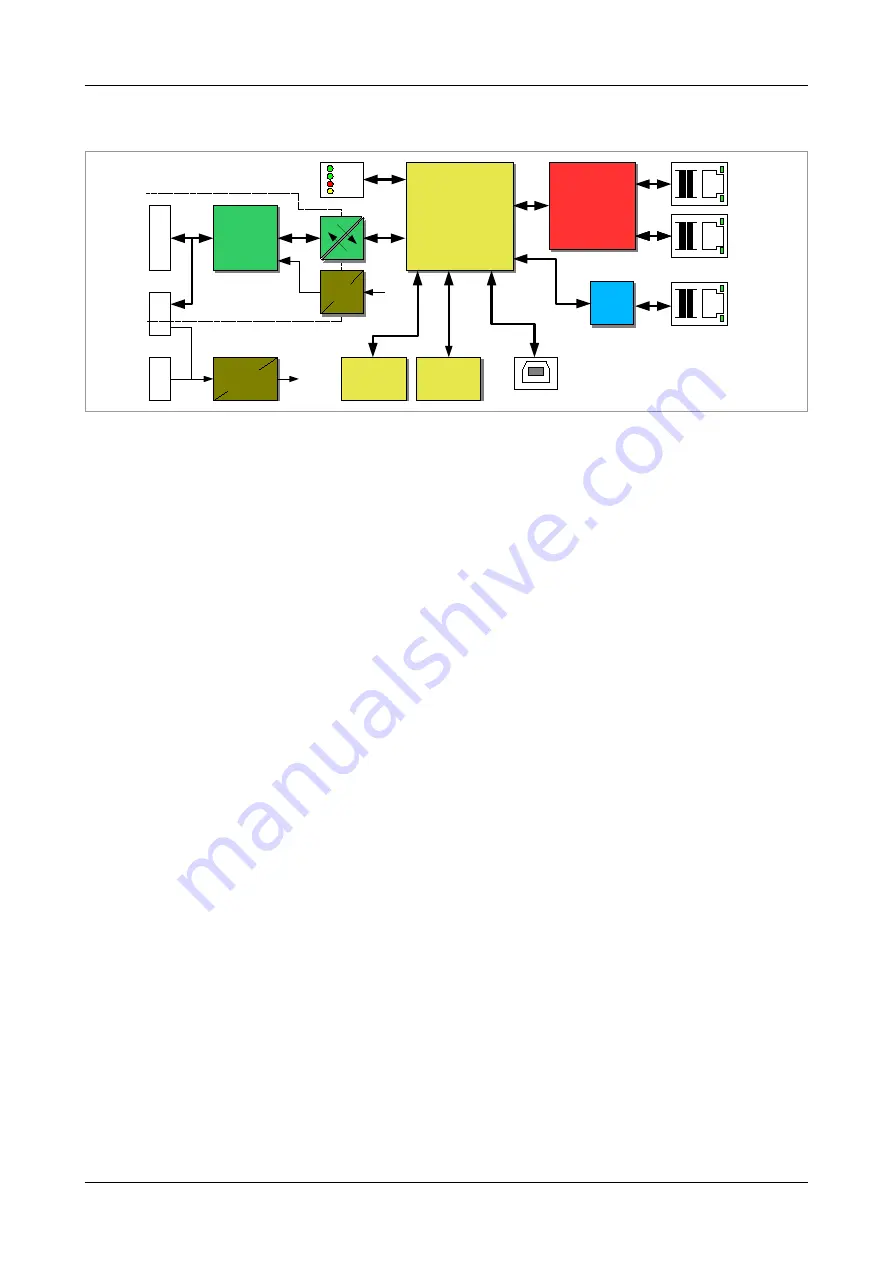
Figure 1:
Block circuit diagram
The CAN-EtherCAT device connects an EtherCAT
®
network with one CAN network. In this case
the gateway acts as an EtherCAT slave device according to „Module Profile Number 5000“ of the
„Modular Device Profile Description“ (ETG.5001 documents).
The CAN-EtherCAT gateway allows CAN modules with CANopen
®
(CiA
®
DS 301) or Layer 2 (ISO
11898-1) implementations to connect with a real-time EtherCAT network. The gateway does not
limit the number of CAN nodes.
The CAN-EtherCAT is also configurable as “Ethernet Switch Port” by Ethernet over EtherCAT
(EoE), see section 5.2.
The high-speed CAN interface is compliant with ISO 11898-2 and it supports transfer rates from
50 kBit/s up to 1 MBit/s. The 100BASE-TX EtherCAT interface is IEEE802.3 compatible and runs
at 100 MBit/s. The CAN interface, as well as the EtherCAT interface, is electrically isolated.
The configuration of the CAN-EtherCAT is accomplished through the EtherCAT master.
CAN diagnostics and firmware updates are realized via web interface. (Firmware updates are also
possible via File access over EtherCAT (FoE), see section 5.3)
Page 10 of 92
Manual • Doc. No.: C.2922.21 / Rev. 1.4
CAN-EtherCAT
Micro-
controller
Micro-
controller
Physical
CAN
Layer
ISO11898-2
Physical
CAN
Layer
ISO11898-2
Power Supply
24 V=
+5V=
+5V=
DC/DC
Converter
5-pole
Open style
Connector
Combicon 5.08
Power Supply
Flash
Flash
SDRAM
SDRAM
LEDs
DIAG
USB-A
E
th
er
C
A
T
Electrical Isolation
In-Rail-Bus
Connector
In-Rail-Bus
Connector
C
A
N
ESC
ET1100
ESC
ET1100
PORT 1
RJ45
100BASE-TX
PORT 2
RJ45
100BASE-TX
PORT 3
RJ45
100BASE-TX
PHY
PHY


