Overview
Installation and technical data
CAN-PCI/360
Rev. 1.3
3
Microcontroller
68360
+5 V=
+5 V=
+5 V=
+5 V=
C
A
N
B
U
S
CAN
CAN
C
A
N
B
U
S
+5 V=
+5 V=
CAN
C
A
N
B
U
S
Physical
CAN
Layer
DC/DC-
Wandler
+5 V=
+5 V=
CAN
C
A
N
B
U
S
Physical
CAN
Layer
DC/DC-
Wandler
Flash EPROM
PCI Card Edge Connector
DRAM
4...32 MByte
QSPAN
CA91860
(32-bit Interface)
I²C
EEPROM
I²C
EEPROM
RS-232 Interface
(Option: RS-422,
RS-485, TTY)
3 serial Interfaces
(TTL Level) or
Ethernet (TTL)
30-pole
SMD Connector
10-pole
Post Connector
Physical
CAN
Layer
electrical isolation
DC/DC
Converter
DSUB9
CiA pinning
CAN Controller
SJA1000
electrical isolation
DC/DC
Converter
CAN Controller
SJA1000
Physical
CAN
Layer
DSUB9
CiA pinning
2nd CAN Interface
only at
CAN-PCI/360-2
34-pole
Post Connector
Multiplex
Bus Interface
electrical isolation
DSUB9
CiA pinning
4th CAN Interface
only at
CAN-PCI/360-4
CAN Controller
SJA1000
Ribbon
Cable
10-pole
Post Conector
electrical isolation
DSUB9
CiA pinning
3rd CAN Interface
only at
CAN-PCI/360-3
CAN Controller
SJA1000
Ribbon
Cable
10-pole
Post Conector
1. Overview
1.1 Description of the Module
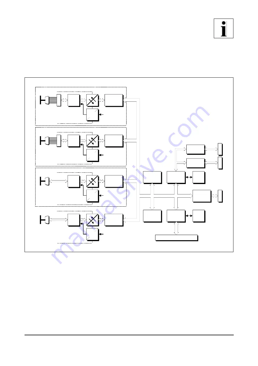
Fig. 1.1.1:
Block circuit diagram of the CAN-PCI/360 module
The module CAN-PCI/360 is a PC-plug-in board for the PCI-bus. It operates with a 68360
microcontroller which is responsible for the local management of CAN-data.
The module can be equipped with four equal CAN-interfaces. Two interfaces are connected directly by
means of 9-pin DSUB-connectors on board, the other two by means of two further DSUB-connectors
which are installed in a separate slot sheet. The CAN-data is buffered in a local DRAM. Data safety and
data consistency of up to 1 Mbit/s are guaranteed.


