-
1
34 -
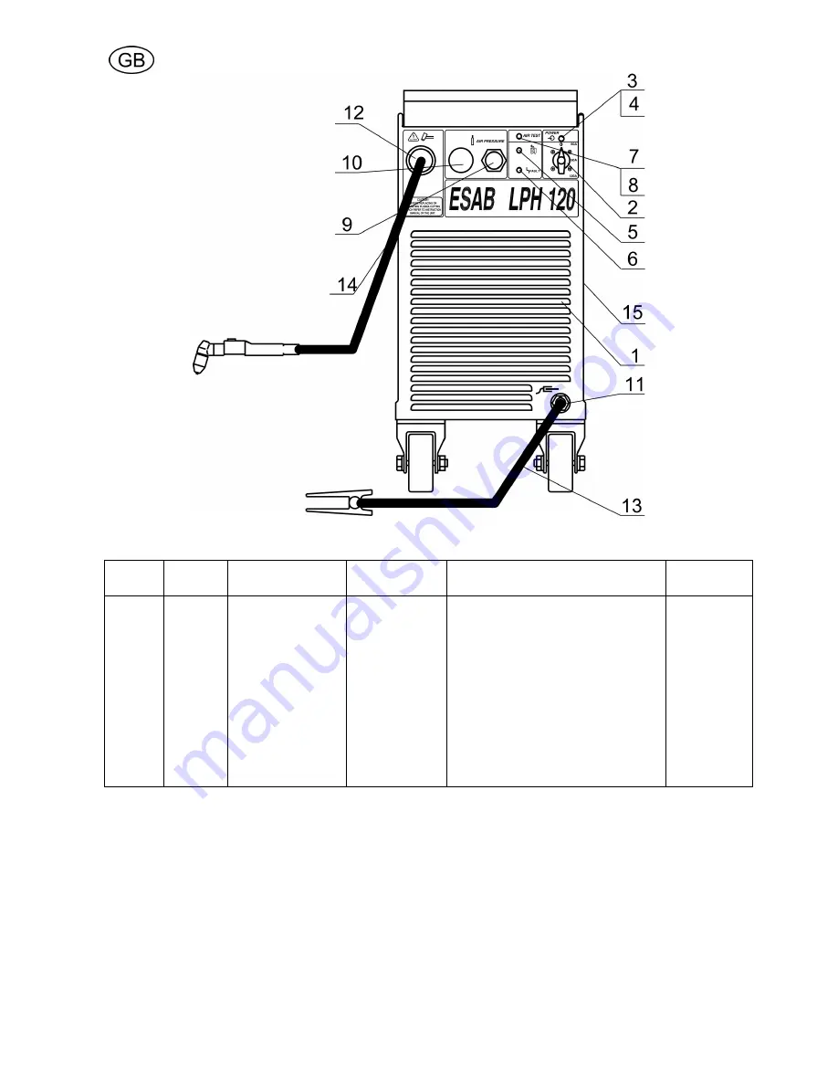
Fig. 9-3. LPH
1
20 Power source – front view
Item No.
Qty. Req.
400-4
1
5V
3~ 50/60Hz
Qty. Req.
230V/400-4
1
5V/440V
3~ 50/60Hz
Part No.
Description
Circuit symbol
1
2
2
3
4
5
6
7
8
9
10
11
12
13
14
15
1
1
-
3
1
1
1
1
1
1
1
1
1
1
1
2
1
-
1
3
1
1
1
1
1
1
1
1
1
1
1
2
0457 291 001
0457 291 002
0349 302 057
0457 290 003
0457 290 004
0457 290 005
0457 290 006
0457 290 007
0457 290 008
0457 290 009
0457 290 010
0457 290 011
0457 290 012
0457 291 018
0558 000 724
0457 290 015
Front cover
Rotary cam – switch
Rotary cam – switch
LED – holder ( socket )
LED ( green )
LED ( red )
LED ( yellow )
Push – button switch
Push – button cap ( detachable )
Pressure regulator
Pressure gauge
Current connector – socket
Rubber grommet ( with support sleeve )
Current wire with clamp
Plasma cutting torch PT 25
Side panel
W1
W1
D1
D3
D2
W2
“ + ”
Содержание LPH 120
Страница 8: ... 138 11 SCHEMATIC DIAGRAM Fig 11 1 Schematic Diagram LPH 120 400 415V ...
Страница 9: ... 139 Fig 11 2 Schematic Diagram LPH 120 230V 230V 400 415V 440V ...
Страница 10: ... 140 Fig 11 3 Schematic Diagram LPH 120 400 415V 230V 400 415V 440V ...
Страница 11: ... 141 Fig 11 4 Schematic Diagram LPH 120 440V 230V 400 415V 440V ...


