


2
USER RESPONSIBILITY
This equipment will perform in conformity with the description thereof contained in this manual and accompanying
labels and/or inserts when installed, operated, maintained and repaired in accordance with the instructions pro-
vided. This equipment must be checked periodically. Malfunctioning equipment should not be used. Parts that
are broken, missing, worn, distorted or contaminated should be replaced immediately. Should such repair or
replacement become necessary, the manufacturer recommends that a telephone or written request for service
advice be made to the Authorized Distributor from whom purchased.
This equipment or any of its parts should not be altered without the prior written approval of the manufacturer. The
user of this equipment shall have the sole responsibility for any malfunction which results from improper use, faulty
maintenance, damage, improper repair or alteration by anyone other than the manufacturer or a service facility
designated by the manufacturer.
TABLE OF CONTENTS
SECTION
TITLE
PAGE
PARAGRAPH
SECTION 1
DESCRIPTION .................................................................................................
7
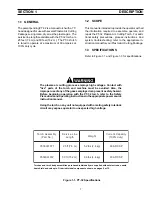
1.1
General .............................................................................................................
7
1.2
Scope ................................................................................................................
7
1.3
Specifications ....................................................................................................
7
1.4
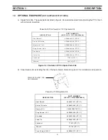
Optional Equipment ...........................................................................................
9
SECTION 2
ASSEMBLY AND OPERATION .......................................................................
10
2.1
General .............................................................................................................
10
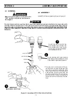
2.2
Assembly ..........................................................................................................
10
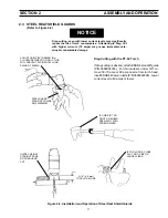
2.3
Steel Heat Shield Guards ..................................................................................
11
SECTION 3
MAINTENANCE ................................................................................................
12
3.1
General .............................................................................................................
12
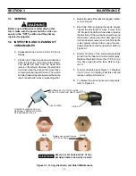
3.2
Inspection and Cleaning of Consumables .........................................................
12
3.3
Removing/Replacing Torch Head and Switch from Service Line .......................
13
SECTION 4
REPLACEMENT PARTS ..................................................................................
14
4.1
General .............................................................................................................
14
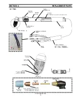
4.2
Parts .................................................................................................................
15


