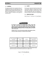
ESAB 0558001971 Скачать руководство пользователя страница 12

12

SECTION  3

 MAINTENANCE

3.1 GENERAL

Before any maintenance is attempted on this
torch, make sure the power switch on the con-
sole is in the "OFF" position and the primary
input is deenergized.

3.2 INSPECTION AND CLEANING OF

CONSUMABLES

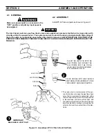
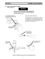
A. Disassemble the front end of the PT-32 as

follows:

1.

Position torch head in a downward direction

(refer to Figure 2-1) and remove the shield.
The nozzle will drop from the head and
remain in the shield. Unscrew the electrode
to remove it and the valve pin. Remove these
components and inspect for wear. The nozzle
and electrode will generally wear at the same
rate. For best performance, replace together.
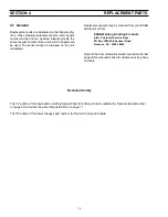
2.

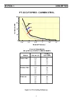
Nozzle: Replace if the orifice is clogged, nicked,

or out-of-round.

3.

Electrode:

 When replacing the nozzle, always

inspect the electrode for wear. If more than
.06" of electrode Hafnium has eroded, replace
the electrode. If the electrode is used beyond
this recommended wear limit, damage to the
torch and power source may occur. Nozzle life
is also greatly reduced when using the elec-
trode below the recommended limit. Refer to
Figure 3-1.

4.

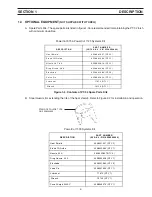
Shield: The face of the shield will gradually

erode from the heat and molten metal spray.
Replace the shield if more than 1/8 inch (3.2
mm) has eroded from the face. Refer to Fig-
ure 3-1.

5.

O-ring: Lubricate as per Figure 3-1. Replace

if cut or worn. Air leaking past this seal will
reduce cutting performance.

B. To replace the above front end components,

refer to Figure 2-1.

HEAT SHIELD

Figure 3-1. O-ring, Electrode, and Shield Maintenance

LUBRICANT (P/N 17672) CAN BE

APPLIED TO O-RING OR HEAT SHIELD.

THE HEAT SHIELD FACE WILL
GRADUALLY ERODE WITH USE.
SEE PARAGRAPH 3.2.A.4.

O-RING

REPLACE ELECTRODE BEFORE PITTING
BECOMES DEEPER THAN .06 INCH (1.5 MM)

NEW

Replace when eroded beyond
.06"(1.5mm) Depth.

WORN

Содержание 0558001971

Страница 1: ...m 52 529 Do NOT permit untrained persons to install operate or maintain this equipment Do NOT attempt to install or operate this equipment until you have read and fully understand these instructions I...

Страница 2: ...his equipment or any of its parts should not be altered without the prior written approval of the manufacturer The user of this equipment shall have the sole responsibility for any malfunction which r...

Страница 3: ...the workpiece which might pro duce flammable or toxic vapors Do not do hot work on closed containers They may explode 4 Have fire extinguishing equipment handy for instant use such as a garden hose w...

Страница 4: ...Never strike an arc on a cylinder 5 For additional information refer to CGA Standard P 1 Precautions for Safe Handling of Compressed Gases in Cylinders which is available from Compressed Gas Associati...

Страница 5: ...un point loign de la zone de travail augmente en effet le risque de pas sage d un courant de sortie par des cha nes delevage AVERTISSEMENT Ces r gles de s curit ont pour objet d assurer votre protect...

Страница 6: ...ations particuli res en mati re de ventilation indiqu es l alin a 6 de la norme Z49 1 de l AWS 5 ENTRETIEN DE L QUIPEMENT Un quipement entretenu de fa on d fectueuse ou inad quate risque non seulement...

Страница 7: ...rc cutting process employs high voltages Contact with live parts of the torch and machine must be avoided Also the improper use of any of the gases employed can present a safety hazard Before beginnin...

Страница 8: ...Cutting Material Thickness In Speed IPM Carbon Steel 1 16 200 1 8 98 1 4 36 3 8 18 1 2 11 Stainless Steel 1 16 138 1 8 58 1 4 18 3 8 10 1 2 6 Aluminum 1 16 200 1 8 110 1 4 48 3 8 17 1 2 14 PT 32 CUT...

Страница 9: ...9 5 7 Q TY 2 Sta nd O ff G uid e 0 5 5 80 0 2 3 9 3 Q TY 1 No zzle 5 0 7 0 A 0 5 5 80 0 2 6 1 8 Q TY 4 D ra g N o zzle 4 0 A 0 5 5 80 0 2 9 0 8 Q TY 1 E le ctro d e 0 5 5 80 0 1 9 6 9 Q TY 3 Va lve P...

Страница 10: ...IN TERLOCK WARNING SECTION 2 ASSEMBLY AND OPERATION The valve pin is a crucial member of the sys tem Its function is to open the gas flow check valve that is permanently assembled within the torch he...

Страница 11: ...CUT Figure 2 2 Installation and Operation of Steel Heat Shield Guards SECTION 2 ASSEMBLY AND OPERATION Drag cutting even with lower current levels may significantly reduce the life of torch consumable...

Страница 12: ...n 06 ofelectrodeHafniumhaseroded replace the electrode If the electrode is used beyond this recommended wear limit damage to the torchandpowersourcemayoccur Nozzlelife is also greatly reduced when usi...

Страница 13: ...a long leads 3 5 Remove the Pilot Arc connection from the Torch Headusingtwowrenchestopreventtwistingstain less steel tube SERVICE LINE ASSEMBLY SWITCH BAND SPLICE CONNECTIONS HANDLE POWER CABLE TORCH...

Страница 14: ...neral Replacement parts are illustrated on the following fig ures When ordering replacement parts order by part number and part name as listed Always provide the seriesorserialnumberoftheunitonwhichth...

Страница 15: ...LVE PIN 0558001959 ELECTRODE 0558001969 NOZZLE 50 70 amp 0558002618 90 amp 0558002837 40 amp drag 0558002908 DETAIL A PT 32 Exploded View POWER CABLE PILOT ARC LEAD 2 WHITE LEADS 4 2 Parts SECTION 4 R...

Страница 16: ...Repair Stations C TECHNICAL SERVICE Telephone 800 ESAB 123 Fax 843 664 4452 Part Numbers Technical Applications Hours 8 00 AM to 5 00 PM EST Performance Features Technical Specifications Equipment Rec...

Отзывы: