6.5 Monitoring your Inverter System
Once you system inverter had been connected to your the Internet, you can monitor the
performance of your system. By following the below instructions:
1.
Go to your web browser and enter the following URL:
www.energystorageaustralia.com<http://www.energystorageaustralia.com>
2.
On the homepage, select “Monitoring portal” on the top menu tab.
3.
As issued by ESA or your retailer, enter your User name and Password (default password
also issued)
4.
We recommend that once you are in the Portal you change your password – which can be
completed at any time once you are first logged in.
5.
The monitoring Portal will enable you to monitor in real time (5 minute reading intervals)
your PV generation, load (consumption), export/import with the grid and if you have
battery storage, your state of Charge
6.
Many other features of the Monitoring portal are available such as accessing historical
data, report generation, grid charging etc. A member of the ESA team can further assist
with the portal features.
From the menu list on top left hand side you would be able to select Overview and see
Generation, Import, Export, consumption, you will see the same info in the graph below if you
place the mouse over the column.
You are able to view by month which shows everyday during that month.
The second thing to look at is My Hybrid, which shows what the system performance is at any
moment, on top of the page you will Graphs which shows the Generation and demanded Power.
7 The Inverter Parameter
Setting
After
set
ting
t
he wifi connection, enter the
set
ting interface of the
websit
e to set inverter
paramet
ers
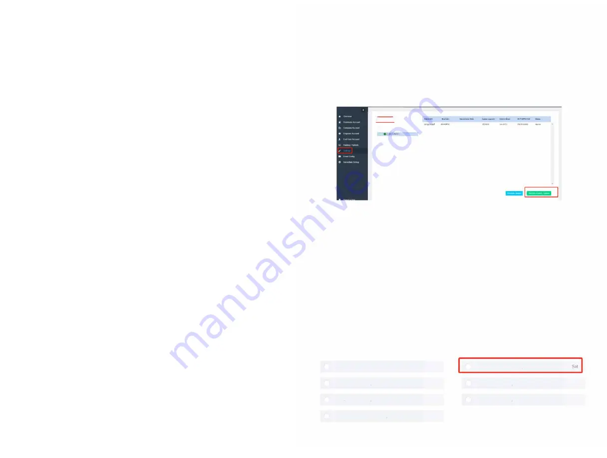
7.1 Click the Settings option in
t
he menu bar, as
show
n in Figure 1
below
Enter
t
he serial number of the
m
achine in
t
he search box.
Select
this machine
Click
Remot
e Control
Option in
t
he lower right corner to enter
t
he
sett
ing
int
erface
Setting Interface
1
S01729P017
1
Q.
-
11
-
H
.&, BOBWISE
-
7.2
Volt-wat
t function
7.2.1 Query Volt -
Watt
Funct
ion
Select
t
he Volt
Watt
Enable (128,0,1) option, and
t
he Volt -
Watt
function shown in the option box
0- Disable
1 - Enable
7 .2.2
Set
the Volt - Watt function
In the option Volt Watt Enable
(128,0
,1), set the value to Enable or prohibit the Volt - Watt
funct
ion
0-Disable
1- Enable
Austra
l
i
a Setting
Set
Set
Set
Set
Volt Watt Enable(128, 0 1)
Volt-var V2(140, 0 3000)
Volt-var V4(138, 0 3000)
Set
PF Model(122, 0, 7)
Volt-varV1(141, 0 3000)
Volt-var V3(139, 0 3000)
Reactive Power Rate(51, 0 50)
Set
7.3 Set volt-var function
7.3.1 Query and set the Volt-var function and volt-var voltage threshold
7.3.1.1 Click Volt-var function enable to select the type for query
7.3.1.2 In the Volt-var function enable selection, set 6 to enable and Oto disable
0-Disable
6 -Enable
Australia Setting
PF Model(122, 0, 7)
se
d
Volt Watt Enable(128, 0, 1)
Vo
l
t-varV1(141
,
0, 3000)
Set
Volt-var V2(140 0 3000)
Volt-var V3(139, 0, 3000)
Set
Volt-var V4(138 0 3000)
Reactive Power Rate(51, 0, 50)
Set
7.3.2 Query and set the Volt-VAR voltage threshold
Set
Set
Set
7.3.2.1 Click the options Volt-VAR Vl, Volt-VAR V2, Volt-VAR V3 and Volt-VAR V4
respectively to query the threshold voltage of the Volt-VAR function
7.3.2.2 Select Volt-var Vl, Volt-VAR V2, Volt-var V3 and Volt-VAR V4 to input the
voltage value to be modified and set
Australia Setting
PF Model(122, 0, 7)
Set
Volt Watt Enable(128, 0, 1)
Set
Volt-varV1(141 0, 3000)
Set
I
I
Volt-var V2(140, 0, 3000)
Set
Volt-var V3(139 0 3000)
Set
I
I
Volt-var V4(138, 0, 3000)
Set
Reactive Power Rate(51, 0, 50)
Set
Giv
Energy
®
28
I
I
27
28


