background image


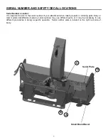
SERIAL NUMBER AND SAFETY DECAL LOCATIONS 


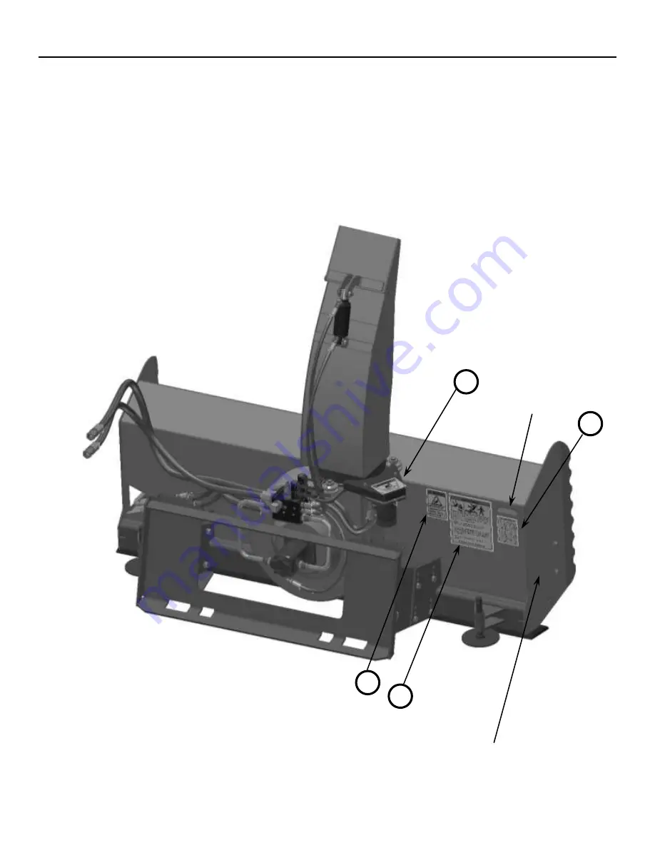
Serial Number Location: 

It is important to refer to the serial number of your attachment when making repairs or ordering parts. Early or 
later  models  (identification  made  by  serial  number)  may  use  different  parts,  or  it  may  be  necessary  to  use 
different  procedures  in  doing  a  specific  operation.    Serial  number  plate  is  located  on  the  right  rear  side  of 
body. 

Serial Plate 

Small Brand Decal 

Содержание 2020 Series

Страница 1: ...Models 2020X 2420X 2420XL Hydraulic Snowblowers For Skid Steer Loaders Operator s Manual Set Up Assembly Maintenance Parts Information Read this Manual Before Use ...

Страница 2: ...CAL LOCATION 5 6 SET UP ASSEMBLY 7 11 MOUNTING INSTRUCTIONS 12 14 OPERATING INSTRUCTIONS 15 16 ROUTINE MAINTENANCE 17 18 AUGER REMOVAL 19 20 FAN REMOVAL 21 PARTS INFORMATION 22 39 WIRE HARNESS INFORMATION 40 GENERAL SPECIFICATIONS 41 TROUBLESHOOTING 42 WARRANTY 43 NOTE Erskine Attachments LLC reserves the right to make improvements in design or changes in specifications at any time without notice ...

Страница 3: ...ds CAUTION WARNING or DANGER are used to indicate hazards Indicates a potentially hazardous situation which if not avoided may result in minor or moderate injury Indicates a potentially hazardous situation which if not avoided could result in death or serious injury Indicates a potentially hazardous situation which if not avoided will result in death or serious injury The word IMPORTANT is used in...

Страница 4: ...le away from loader attachment and discharge when in use This attachment sends objects flying and has rotating parts NEVER direct discharge toward people rocks and debris can be thrown Operation continued NEVER operate near embankments or terrain that is so steep that rollover could occur Always stay in the operator position when using the attachment Before leaving the operators position disengage...

Страница 5: ...our attachment when making repairs or ordering parts Early or later models identification made by serial number may use different parts or it may be necessary to use different procedures in doing a specific operation Serial number plate is located on the right rear side of body B D C A Serial Plate Small Brand Decal ...

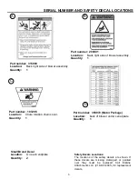
Страница 6: ...989 Location Back right side of blower assembly Quantity 1 Part number 350070 Motor Package Location back of blower under serial plate Quantity 1 Safety Decals Locations The locations of the safety decals are shown If these decals are missing damaged or painted over they must be replaced Call Erskine Attachments LLC 218 435 4045 for replacement decals Small Brand Decal Location On each endplate Qu...

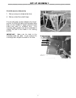
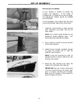
Страница 7: ...ed in the lower position for most skid steers with standard sized tires or in the middle or upper position for skid steers with taller or oversized tires The mounting plate position can also be adjusted to change the pitch of the blower in the working position IMPORTANT Make sure the bolts on the mounting plate are tight If you remove the mounting plate retighten the bolts to 130 ft lbs ...

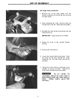
Страница 8: ...s 4 Rotate the chute to the straight forward position 5 Remove the chain shield 6 Loosen the chute rotation motor bolts Push the motor all the way towards the chute Install the No 40 roller chain around the sprocket 7 Tighten the chute chain by pulling the motor outward to remove all slack Tighten the motor bolts and install the chain shield Do not operate the snowblower without the chain shield i...

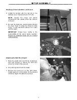
Страница 9: ...ut the hoses getting caught IMPORTANT Proper hose routing is the responsibility of the owner and or operator Pinched or stretched hoses are not covered under warranty Adjusting the Skid Shoe Height 1 Raise the loader arms and tilt the snowblower back just enough to remove the skid shoe about 12 inches off the ground 2 Stop the engine and exit the loader 3 Remove the lynch pin on the skid shoes Ins...

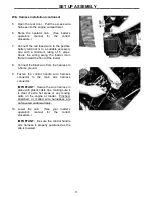
Страница 10: ...erent ways We recommend it be positioned as shown 2 Put a cable tie around the wiring harness and the steering lever 3 Install the wire harness receptacle bracket on either the loader arm or near the hydraulic quick couplers NOTE It may be necessary to make an adapter bracket in order to attach the wire harness to the loader 4 Route the wire harness back along the loader arms and fasten with cable...

Страница 11: ...8 Connect the black wire from the harness to a frame ground 9 Fasten the control handle wire harness connector to the main wire harness connector IMPORTANT Secure the wire harness in place with plastic cable ties making sure it is clear of extra hot areas or any moving parts on the engine or loader Pinched stretched or melted wire harnesses are not covered under warranty 10 Lower the cab See your ...

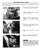
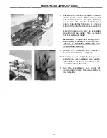
Страница 12: ...e loader to the rear of the snowblower Put the loader quick attach coupler into the snowblower mounting bracket 4 Tilt the loader coupler backward a small amount until it is fully engaged in the snow blower mounting bracket 5 Stop the engine and engage the parking brake 6 Secure the coupler locking mechanism that attaches the snow blower to the loader Coupler wedges or pins must extend through the...

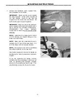
Страница 13: ...hydraulic components to fail and is not covered under warranty NOTE Attachment is shipped with 12FJX 1 1 16 Female JIC Swivel fittings on the ends of the lead hoses NOTE Make sure the pressurized hose is routed to the P port of the valve block If it isn t the blower will not operate properly NOTE The pressure line on the snowblower has a RED cable tie on the hose end See loader s operator s manual...

Страница 14: ...g that best suits your loader IMPORTANT Proper hose routing is the responsibility of the owner and or operator Pinched or stretched hoses are not covered under warranty 9 Connect the snowblower wire harness to the loader wire harness receptacle 10 Mounting is now complete and you are ready to use the snowblower Use reverse order of above instructions to dismount the snow blower from the loader 11 ...

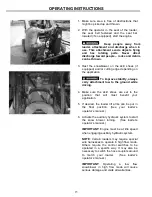
Страница 15: ...e ground while driving 4 Make sure the skid shoes are set to the position that will most benefit your application 5 If desired the loader lift arms can be put in the float position See your loader s operator s manual 6 Activate the auxiliary hydraulic system to start the snow blower turning See loader s operator s manual IMPORTANT Engine must be at idle speed when engaging auxiliary hydraulic syst...

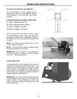
Страница 16: ...ver functions refer to your loader s operator s manual NOTE The loader travel speed is determined by the depth and density of the snow IMPORTANT Do not operate the snowblower if excessive vibration is present Serious damage can occur Check auger and fan Cutting Edge Angle The snowblower can be angled front to back by rolling the mounting plate forward and back This allows for non cutting riding on...

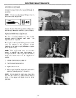
Страница 17: ...r anything else that could cause a potential service or safety problem Preventive maintenance is the easiest and least expensive type of maintenance IMPORTANT Bolts and set screws can loosen after initial usage After the first hour of operation check all bolts and set screws Lubrication Use No 2 lithium base gun grease when lubricating all snowblower grease fittings Add no more than 2 pumps of gre...

Страница 18: ...s shear protected by pressure relief valve A located in the hydraulic control manifold on the rear of the snowblower directly above the fan motor NOTE The auger relief valve is set at the factory to assure the best performance in average conditions If the auger should stall too easily the relief valve can be adjusted as follows 1 Loosen the lock nut on valve A 2 Turn the set screw one turn 3 Tight...

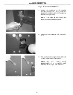
Страница 19: ...er travel NOTE This frees up the bearing and allows it to slide on the auger shaft 2 Disconnect the tubelines from the auger motor 3 Remove the two bearing retaining bolts and the four auger motor housing bolts NOTE Pry the bearing flange approximately 1 4 to the inside to allow clearance for the auger to be removed ___________________ AUGER REMOVAL ____________________ ...

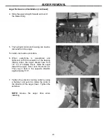
Страница 20: ...e exception of the bearing locking collar the auger should have from 1 4 to 1 2 endplay travel Slide the auger toward the auger motor until it bottoms out Then tap it back in the opposite direction approximately 1 16 7 Tighten the eccentric locking collar by using a hammer and punch to rotate the collar in the direction of the auger travel Tighten the setscrew NOTE Grease the auger drive when inst...

Страница 21: ... keep the fan from rotating when loosening or tightening the castle nut 3 Remove the fan from the tapered motor shaft with a pulley puller 4 To install use reverse procedure IMPORTANT On the 2020 and 2420 models the castle nut must be torqued to a minimum of 250 ft lbs On the 2420XL model the castle nut must be torqued to a minimum of 400 ft lbs ___________________ FAN REMOVAL ____________________...

Страница 22: ... B 50 DB 1 300498 CUTTING EDGE B 56 DB 1 312428 CUTTING EDGE B 62 DB 40 8 13309 BOLT HEX 5 8 X 1 1 2 NC GR 5 41 8 33630 WASHER LOCK 5 8 48 9 33630 WASHER LOCK 5 8 54 10 33630 WASHER LOCK 5 8 60 42 3 13213 BOLT HEX 1 2 X 2 1 2 NC GR 5 43 2 13209 BOLT HEX 1 2 X 1 1 2 NC GR 5 45 8 36114 NUT HEX FULL 5 8 NC 48 9 36114 NUT HEX FULL 5 8 NC 54 10 36114 NUT HEX FULL 5 8 NC 60 46 7 37214 NUT HEX LOCK 1 2 N...

Страница 23: ...23 2020 X MINI SNOWBLOWER PARTS INFORMATION ...

Страница 24: ... 1 1 400000 MOUNT FRAME TORO MINI W A MNT PKG 400540 2 1 330622 MOUNT FRAME AVANT MINI W A MNT PKG 330753 3 1 400001 MOUNT FRAME ASV MINI W A MNT PKG 400541 4 1 400002 MOUNT FRAME BC MINI W A MNT PKG 400542 44 6 15209 BOLT HEX 1 2 X 1 1 2 NC GR 8 46 6 0167011 NUT FLG TOP LOCK 1 2 NC GR 8 YZ ...

Страница 25: ...1 350027 AUGER SERRATED 16D X 54 W A PAINTED OPT PKG 350101 1 350029 AUGER SERRATED 16D X 60 W A PAINTED OPT PKG 350102 1 28 100832 BRG 1 25 2 B FLG 1 30 310037 MOTOR CAN PAINTED 1 36 13210 BOLT HEX 1 2 X 1 3 4 NC GR 5 2 44 11104721 BOLT FLNG SERRATED 1 2 X 1 1 4 NC GR 5 6 45 22876 BOLT FLNG 12PT 1 2 X 1 1 2 NC 4 46 37214 NUT REV LOCK 1 2 NC GR 5 8 51 103880 WASHER LOCK 3 8 1 53 103879 BOLT HEX 3 ...

Страница 26: ...1 315880 BACKING PLATE SB 51 WITH OPT URE RUB PKG 1 315463 BACKING PLATE SB 57 WITH OPT URE RUB PKG 1 22 315467 SKID SHOE URETHANE OPTIONAL SKID SHOE PKG 2 23 300086 SKID SHOE HEAVY DUTY OPTIONAL SKID SHOE PKG 2 35 315942 BRACKET URETHANE 45 W A WITH OPT URE RUB PKG 1 315874 BRACKET URETHANE 51 W A WITH OPT URE RUB PKG 1 315875 BRACKET URETHANE 57 W A WITH OPT URE RUB PKG 1 38 13211 BOLT HEX 1 2 X...

Страница 27: ...136 HOSE 1 4 X 22 6MB 4FJX CASE DRAIN 1 17 103497 ADPT ELB 4MB 4MJ 90 CASE DRAIN 1 18 315951 HOSE 3 4 X 35 12MB 12FJX FOR 48 SNOWBLOWER 2 315451 HOSE 3 4 X 24 5 12MB 12MJ FOR 60 SNOWBLOWER 2 19 315143 HOSE 3 4 X 72 12FJX 12MB LEAD RETURN 1 20 315091 HOSE 3 4 X 72 12FJX 12MB LEAD RED ZIP TIE TO PORT P 1 21 315092 HOSE 3 8 X 21 6MB 6FJX CHUTE ROTATION 2 22 315094 HOSE 1 4 X 46 6MB 2MP CHUTE DEFLECTI...

Страница 28: ... BUSHING 3 15 37820 COUPLING NUT 3 8 X 1 3 4 Z 2 34 315940 CUTTING EDGE B 50 DB 1 300498 CUTTING EDGE B 56 DB 1 312428 CUTTING EDGE B 62 DB 1 318430 CUTTING EDGE B 74 DB 1 300488 CUTTING EDGE B 80 DB 1 318474 CUTTING EDGE B 86 DB 1 40 13309 BOLT HEX 5 8 X 1 1 2 NC GR 5 8 41 33630 WASHER LOCK 5 8 13 48 14 54 14 60 15 72 15 78 16 84 42 13213 BOLT HEX 1 2 X 2 1 2 NC GR 5 3 43 13209 BOLT HEX 1 2 X 1 1...

Страница 29: ...29 2020 PARTS INFORMATION_______________ ...

Страница 30: ...09 BOLT HEX 5 8 X 1 1 2 NC GR 5 5 8 X 1 1 2 NC GR 5 41 14 33630 WASHER LOCK 5 8 54 60 15 33630 WASHER LOCK 5 8 72 78 16 33630 WASHER LOCK 5 8 84 17 33630 WASHER LOCK 5 8 96 42 3 13213 BOLT HEX 1 2 X 2 1 2 NC GR 5 43 2 13209 BOLT HEX 1 2 X 1 1 2 NC GR 5 44 8 13207 BOLT HEX 1 2 X 1 1 4 NC GR 5 10 13207 BOLT HEX 1 2 X 1 1 4 NC GR 5 2420XL SNOWBLOWER 45 13 36114 NUT HEX FULL 5 8 NC 54 14 36114 NUT HEX...

Страница 31: ...31 2420 2420XL PARTS INFORMATION ...

Страница 32: ...H OPT URE RUB PKG 1 315880 BACKING PLATE SB 51 WITH OPT URE RUB PKG 1 315463 BACKING PLATE SB 57 WITH OPT URE RUB PKG 1 315464 BACKING PLATE SB 69 WITH OPT URE RUB PKG 1 315465 BACKING PLATE SB 75 WITH OPT URE RUB PKG 1 315466 BACKING PLATE SB 81 WITH OPT URE RUB PKG 1 315969 BACKING PLATE SB 96 WITH OPT URE RUB PKG 1 22 315467 SKID SHOE URETHANE OPTIONAL SKID SHOE PKG 2 23 300086 SKID SHOE HEAVY ...

Страница 33: ...TED OPT PKG 350101 1 350029 AUGER SERRATED 16D X 60 W A PAINTED OPT PKG 350102 1 350031 AUGER SERRATED 16D X 72 W A PAINTED OPT PKG 350103 1 350033 AUGER SERRATED 16D X 78 W A PAINTED OPT PKG 350104 1 350035 AUGER SERRATED 16D X 84 W A PAINTED OPT PKG 350105 1 28 100832 BRG 1 25 2 B FLG 1 30 310037 MOTOR CAN PAINTED 1 36 13210 BOLT HEX 1 2 X 1 3 4 NC GR 5 2 44 11104721 BOLT FLNG SERRATED 1 2 X 1 1...

Страница 34: ...W A PAINTED 1 350091 AUGER SERRATED 18D X 72 W A PAINTED 1 350093 AUGER SERRATED 18D X 78 W A PAINTED 1 350095 AUGER SERRATED 18D X 84 W A PAINTED 1 350097 AUGER SERRATED 18D X 96 W A PAINTED 1 28 100832 BRG 1 25 2 B FLG 1 30 310037 MOTOR CAN PAINTED 1 36 13210 BOLT HEX 1 2 X 1 3 4 NC GR 5 2 44 11104721 BOLT FLNG SERRATED 1 2 X 1 1 4 NC GR 5 4 45 22876 BOLT FLNG 12PT 1 2 X 1 1 2 NC GR 9 2420 4 228...

Страница 35: ...B 6MJ 90 2 13 103318 ADPT STR 2MP 2FPX 1 14 103284 ADPT ELB 2MP 2FPX 90 1 16 315136 HOSE 1 4 X 22 6MB 4FJX CASE DRAIN 1 17 103497 ADPT ELB 4MB 4MJ 90 CASE DRAIN NOT USED ON XL 1 18 315951 HOSE 3 4 X 35 12MB 12FJX FOR 48 SNOWBLOWER 2 315451 HOSE 3 4 X 24 5 12MB 12MJ FOR 60 SNOWBLOWER 2 315452 HOSE 3 4 X 30 5 12MB 12MJ FOR 72 SNOWBLOWER 2 315453 HOSE 3 4 X 33 5 12MB 12MJ FOR 78 SNOWBLOWER 2 315454 H...

Страница 36: ...36 HYDRAULIC PARTS INFORMATION ...

Страница 37: ... 2 422189 HOSE 3 8 X 60 6FJX 6FJX CHUTE ROTATION 3 2 103330 ADPT ELB 10MB 6MB 90 CHUTE ROTATION 4 1 103284 ADPT ELB 2MP 2FPX 90 DEFLECTOR CYL ROD END 5 1 103318 ADPT STR 2MP 2FPX DEFLECTOR CYL BASE END 6 2 201934 COUPLER HYD 3 8 8OR M FF AUX HOSES 7 2 201933 COUPLER HYD 3 8 8OR FM FF AUX HOSES 8 4 201925 ADPT STR 8MB 6MJ AUX HOSES ...

Страница 38: ...TOCK NO 1 1 315825 TUBELINE FAN RETURN XL 2 1 315824 TUBELINE FAN PRESSURE XL 3 1 315136 HOSE 1 4 X 22 6MB 4FJX CASE DRAIN 4 2 201528 ADPT STR 16MB 16MJ 5 1 300499 ADPT ELB 12MB 16MJ 90 6 4 320102 ADPT PLUG 6MB 7 1 201526 ADPT STR 12MB 16MJ 8 1 203212 ADPT STR 4MB 4MJ CASE DRAIN ...

Страница 39: ...P TIE TO PORT P 3 2 315451 HOSE 3 4 X 24 5 12MB 12MJ 2420XL X 60 2 315452 HOSE 3 4 X 30 5 12MB 12MJ 2420XL X 72 2 315453 HOSE 3 4 X 33 5 12MB 12MJ 2420XL X 78 4 2 315424 TUBELINE AUGER PRESSURE 5 2 202113 ADPT STR 10MB 12MJ 9 2 103431 ADPT STR 12MB 12MJ LEAD HOSES 10 1 320223 COUPLER HYD 3 4 12OR M FF ASV LEAD HOSE TO PORT P 11 1 320222 COUPLER HYD 3 4 12OR FM FF ASV LEAD HOSE TO PORT T ...

Страница 40: ...y 1 3 202489 RECEPTACLE BRACKET loader harness 1 4 315127 ATTACHMENT HARNESS assembly 1 Optional Harnesses not shown PART NO DESCRIPTION 320256 14 PIN UNIVERSAL for Bobcat Loaders 320233 14 PIN UNIVERSAL for Case New Holland Loaders 320084 14 PIN UNIVERSAL for John Deere Loaders 200008 8 PIN for Caterpillar A series Loaders 315153 8 PIN for ASV Loaders 315339 8 PIN for Caterpillar B series ...

Страница 41: ...30 50 GPM for XL 30 50 GPM for XL 30 50 GPM for XL 30 50 GPM Operating Weight 765 lbs 800 lbs 875 lbs 910 lbs 940 lbs 1050 lbs 850 for XL 915 for XL 950 for XL 980 for XL Model 2020 x 49 2020 x 55 2020 x 61 2020 x 73 2020 x 79 2020 x 85 Working Width 49 55 61 73 79 85 Overall Width 51 57 63 75 81 87 Height 29 29 29 29 29 29 Fan Diameter 20 4 blade 20 4 blade 20 4 blade 20 4 blade 20 4 blade 20 4 b...

Страница 42: ...r at slower ground speed Make sure loader is at full throttle Make sure High Flow mode is engaged if operating a high flow snowblower Chute functions will not operate Check harness connections Check to make sure you are operating he correct loader buttons read loader s operator manual Check power and ground leads if using pistol grip harness Check fuse if using pistol grip harness Isolate bad sole...

Страница 43: ...r them be liable for incidental or consequential damages or injuries including but not limited to the loss of profit rental or substitute equipment or other commercial loss Purchaser s sole and exclusive remedy being as provided here in above Erskine Attachments LLC must receive immediate notification of defect and no allowance will be made for repairs without our consent or approval This warranty...

Страница 44: ...44 P N 350099 Date Printed 11 26 2018 Erskine Attachments LLC Printed in U S A ...

Отзывы: