7
ULTRA
Quick installation and programming guide
English
WARNING
This quick guide is a summary of the complete installation manual. The manual contains safety warnings and
other explanations which must be taken into account. The most recent version of this guide and the
installation manual are available at the "Downloads" section on Erreka's website:
http://www.erreka-automation.com
The options and functions described in this guide apply for the firmware version indicated on the circuit. The
firmware, as part of a process of continuous improvement, is subject to new functionalities or upgrades being
included as a result of new versions which are not necessarily compatible with previous ones. For this reason,
some options or functions may differ or be unavailable if your firmware is older than shown in this guide.
E289A
D289A
L
L
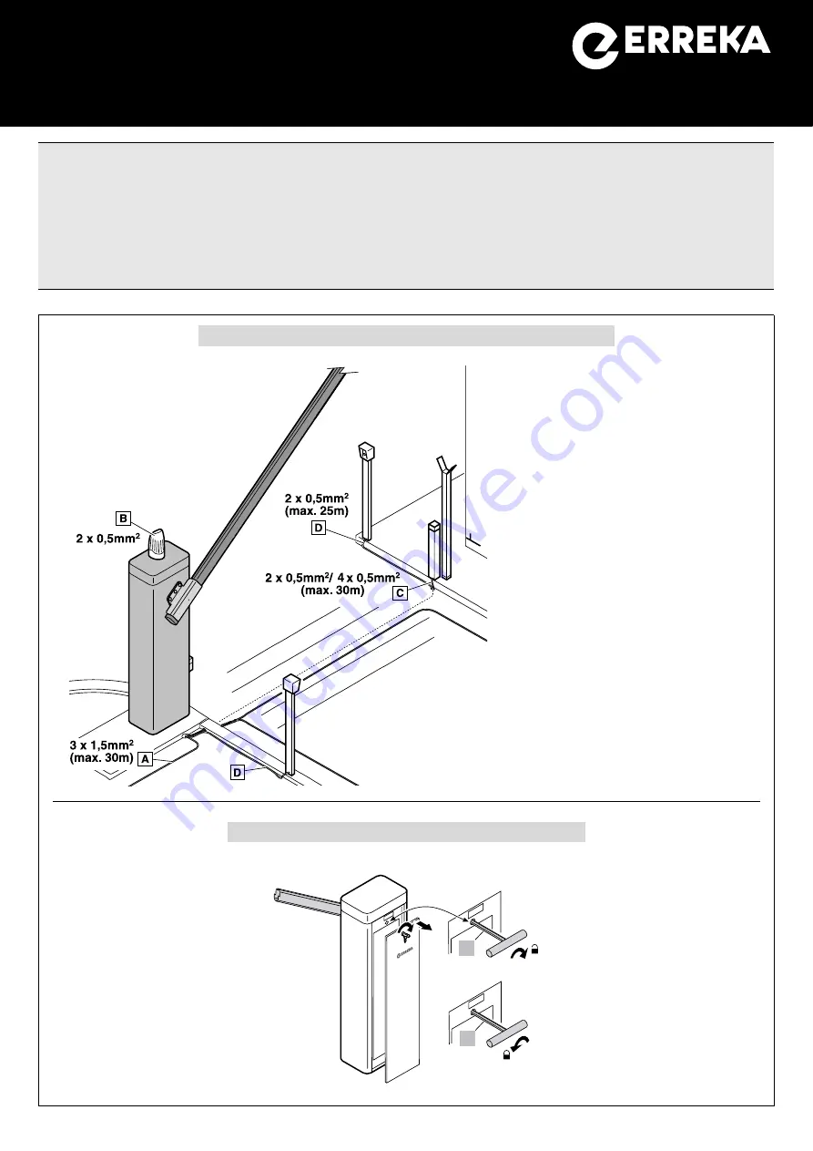
Electrical wiring
A: Main power supply
3x1,5mm
2
(max. 30m)
B: Flashing light
2x0,5mm
2
C: Photocells (Tx / Rx)
2x0,5mm
2
/ 4x0,5mm
2
(max. 30m)
D: Key switch
2x0,5mm
2
(max. 25m)
Elements of the complete installation
Unlocking
Unlocking should be
carried out with caution.
The internal spring may
cause jolting if the barrier
is not balanced or the arm
is not mounted.
Unlocking
(manual operation):
turn the key (L) clockwise
until it stops.
Locking
(motorised operation)
:
turn the key (L) anti-clockwise
until locked.
The drawing shows a right-side
barrier (ULS6ECD, ULS45ECD,
ULS3ECD)
ONLY UNLOCK THE
BARRIER IF THE ARM IS
INSTALLED.
MSU-021/01
V1.18b
or later


