5
1.4
Connectors
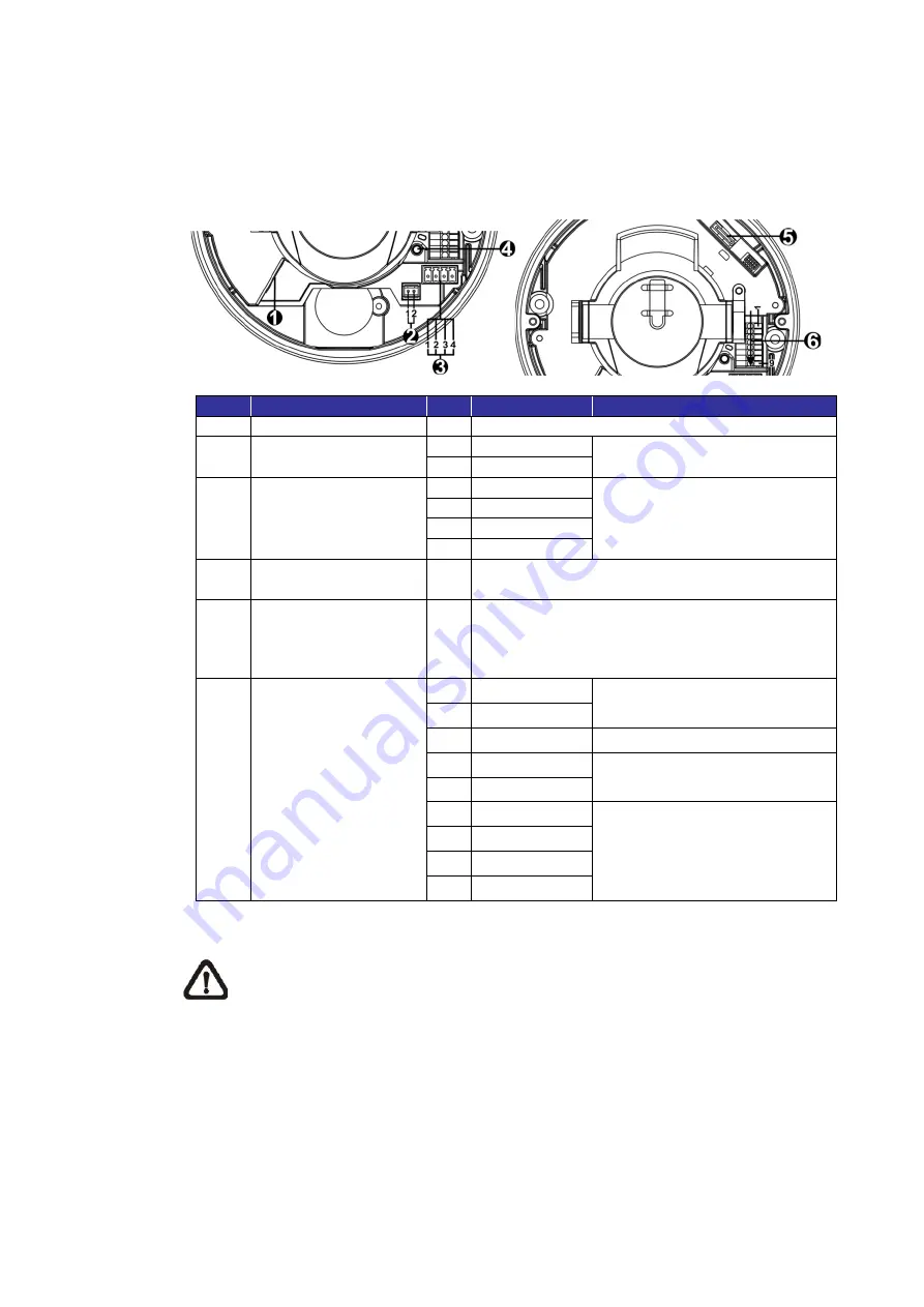
The diagram below shows the default button and various connectors of the
camera. Definition for each connector is given as follows.
No.
Connector
Pin
Definition
Remarks
1
RJ-45
- For network and PoE connections
2
BNC*
1 GND
For analog video output
2 BNC
3
Power
(DC 12V / AC 24V)
1 AC 24V 1
Power connection
2 AC 24V 2
3 DC 12V 1
4 DC 12V 2
4
Default Button
- Press the default button with a proper tool for
at least 20 seconds to restore the camera.
5
microSD Card Slot
-
Insert the microSD card into the card slot to
store videos and snapshots. Do not remove
the microSD card when the camera is powered
on.
6
Alarm & Audio I/O
1 Audio In L
Audio In (Line In)
2 Audio In R
3 GND
Ground connection
4 Audio Out L
Audio Out (Line Out)
5 Audio Out R
6 Alarm Out +
Alarm connection
**Do
NOT
connect external
power supply to the alarm I/O
connector of the IP camera.
7 Alarm Out
−
8 Alarm In +
9 Alarm In
−
*Please contact the manufacturer for the compatible BNC cable.
NOTE:
It is not recommended to record with the microSD card for 24/7
continuously, as it may not be able to support long term continuous data
read/write. Please contact the manufacturer of the microSD card for
information regarding the reliability and life expectancy.


