background image

 The CADWELD

®

 ONE SHOT Process

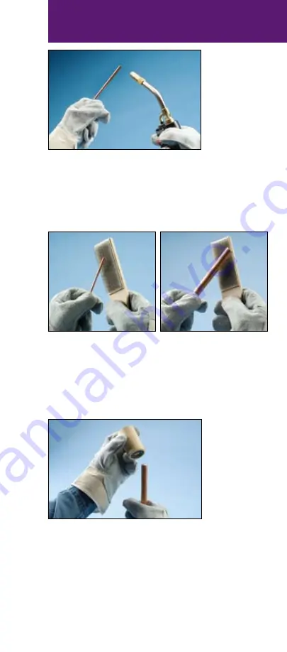
Fig. 4 

The conductors should be clean and dry before the  

connection is made. Use a propane torch to dry wire 

conductors and remove remaining cleaning residue, 

solvent, or water before making the CADWELD

®


ONE SHOT connection.

Fig. 5 

Next, use a wire brush to further prepare the surface  

of the conductors and ground rod (CADWELD

®

 T-313  

or T-314  brush).

Scrape the outer surface to remove dirt and oxidation. 

You will notice a slight color change.

Fig. 6 

Each CADWELD ONE SHOT contains a rubber  

grommet at the bottom of the mold.

Gently turn the CADWELD ONE SHOT onto the  

ground rod until the ground rod reaches the stopper 

and cannot go any further.

29

Содержание Eritech Cadweld

Страница 1: ...Exothermic Welding Manual CADWELD...

Страница 2: ...E VESSELS For use with cast iron pipe or heavy casting meeting ASTM A47 84 A48 83 A126 84 A278 85 or A377 89 DO NOT USE ON CAST IRON SOIL PIPE ASTM A74 93 Evaluate possible effects of CADWELD connecti...

Страница 3: ...are a general demonstration of a typical welded connection These basic steps are used for all CADWELD electrical connections Be sure to read and follow the instructions included with every mold before...

Страница 4: ...welding material natural bristle brush for mold cleaning wire brush for cleaning preparing conductors flint igniter and propane torch NOTE Additional materials may be required for your specific applic...

Страница 5: ...4 other materials required The mold must be correct for the conductor size and application DO NOT MODIFY MOLDS Fig 5 Remove the small wire bracket which is used to temporarily hold the mold together b...

Страница 6: ...mbscrews onto the mold Fig 8 Close the grips to tightly lock the mold Check for an appropriate seal on the mold Fig 9 If the mold does not seal properly make adjustments to tighten loosen the handle c...

Страница 7: ...ors should be clean and dry before the connection is made Use a propane torch to dry wire conductors and remove remaining cleaning residue solvent or water before making the CADWELD connection Fig 12...

Страница 8: ...e conductors and position them for the connection Fig 14 Close the clamp tightly once the conductors are properly positioned Fig 15 Steel disk found inside the packaging box of welding material 6 The...

Страница 9: ...ld Hold the steel disk on the side of the mold and let it slide into place Fig 17 Ensure that the steel disk is properly seated Fig 18 Next take a tube of properly sized welding material as identified...

Страница 10: ...ible Fig 20 Quickly pour the loose welding material powder into the mold Fig 21 The bottom of the tube contains compressed material starting material Tap the bottom of the tube a couple of times to lo...

Страница 11: ...ial with temperatures in excess of 2500 degrees Fahrenheit 1400 degrees Celsius and a localized release of smoke Avoid looking directly at the flash of light from ignition of starting material Avoid i...

Страница 12: ...llers Inspectors Section Appendix A to see whether a quality connection has been made Fig 26 Completed CADWELD connection Fig 27 CADWELD graphite molds will last approximately 50 connections Use a sof...

Страница 13: ...ing material cup natural bristle brush for mold cleaning wire brush for cleaning preparing conductors control unit and propane torch NOTE Additional materials may be required for your specific applica...

Страница 14: ...ther materials required The mold must be correct for the conductor size and application DO NOT MODIFY MOLDS Fig 5 Remove the small wire bracket which is used to temporarily hold the mold together befo...

Страница 15: ...crews onto the mold Fig 8 Close the grips to tightly lock the mold Check for an appropriate seal on the mold Fig 9 If the mold does not seal properly make adjustments to tighten loosen the handle clam...

Страница 16: ...should be clean and dry before the connection is made Use a propane torch to dry wire conductors and remove remaining cleaning residue solvent or water before making the CADWELD connection Fig 12 Nex...

Страница 17: ...the clamp tightly once the conductors are properly positioned Fig 15 Remove the proper CADWELD PLUS welding material cup from the plastic container Inspect the cup to ensure it is tightly sealed and t...

Страница 18: ...n strip nests into the recess on the top edge when the cover is closed Fig 17 Battery powered control unit Fig 18 Place the ignition strip into the control unit connector Remove or protect fire hazard...

Страница 19: ...change to a constant light At this time the unit will send a charge to the ignition strip The ignition strip will spark inside the metal cup initiating the CADWELD PLUS exothermic reaction Allow appro...

Страница 20: ...stallers Inspectors Section Appendix A to see whether a quality connection has been made Fig 23 Completed CADWELD connection Fig 24 CADWELD graphite molds will last approximately 50 connections Use a...

Страница 21: ...es a CADWELD EXOLON graphite mold handle clamp welding material wire brush for cleaning preparing conductors battery pack and propane torch NOTE Additional materials may be required for your specific...

Страница 22: ...her materials required The mold must be correct for the conductor size and application DO NOT MODIFY MOLDS Fig 5 Remove the small wire bracket which is used to temporarily hold the mold together befor...

Страница 23: ...ld Check for an appropriate seal on the mold Fig 9 If the mold does not seal properly make adjustments to the handle clamp Fig 10 Graphite absorbs moisture Ignite the propane torch and dry out the ins...

Страница 24: ...fore making the CADWELD connection Fig 12 Next use a wire brush to further prepare the surface of the conductors and ground rod CADWELD T 313 or T 314 brush Scrape the outer surface to remove dirt and...

Страница 25: ...st be changed every 4 connections NOTE If using XL200 welding material or higher 3 filters 1 white 2 black are included in the weld metal package Insert the white filter between the black filters Fig...

Страница 26: ...side up into the mold Hold the steel disk on the side of the mold and let it slide into place Fig 19 Ensure that the steel disk is properly seated Fig 20 Next take the tube of welding material includ...

Страница 27: ...s Celsius and a localized release of smoke Avoid direct eye contact with flash of light from ignition of starting material Avoid inhalation of smoke fumes Fig 22 Place the graphite CADWELD EXOLON cove...

Страница 28: ...26 Using the CADWELD EXOLON battery pack press the button At this time the unit will send a charge to the igniter pin The igniter pin will initiate the CADWELD EXOLON exothermic reaction Allow approx...

Страница 29: ...connection has been made Fig 29 Completed CADWELD connection Fig 30 CADWELD EXOLON graphite molds will last approximately 50 connections Use a soft cotton cloth or a soft bristle brush ERICO part T394...

Страница 30: ...Additional materials may be required for your specific application Refer to your mold instructions Advise nearby personnel of welding operations in the area prior to ignition Fig 3 Check to ensure the...

Страница 31: ...SHOT connection Fig 5 Next use a wire brush to further prepare the surface of the conductors and ground rod CADWELD T 313 or T 314 brush Scrape the outer surface to remove dirt and oxidation You will...

Страница 32: ...nto the CADWELD ONE SHOT with the concave side facing up Fig 9 Ensure that the steel disk is properly seated inside the CADWELD ONE SHOT Fig 10 Next take the tube of welding material included in the C...

Страница 33: ...couple of times to loosen this material Fig 14 Pour the starting material onto the CADWELD ONE SHOT cover NOTE Welding material is an exothermic mixture and reacts to produce hot molten material with...

Страница 34: ...econds for completion of the reaction and solidification of the molten material Fig 16 Break the ceramic CADWELD ONE SHOT mold off of the connection Avoid contact with hot materials See the Installers...

Страница 35: ...ors control unit and propane torch NOTE Additional materials may be required for your specific application Refer to your mold instructions Fig 3 Check to ensure the ceramic mold is not worn or broken...

Страница 36: ...CADWELD connection Fig 5 Next use a wire brush to further prepare the surface of the conductors and ground rod CADWELD T 313 or T 314 brush Scrape the outer surface to remove dirt and oxidation You w...

Страница 37: ...nection Fig 8 Inspect the cup to ensure it is tightly sealed and the ignition strip is securely attached to the seal Fig 9 Place the welding material cup into the top of the mold Make sure the ignitio...

Страница 38: ...press the button and hold while you observe the ready indicator light A green light will blink for a few seconds and then will change to a constant light At this time the unit will send a charge to th...

Страница 39: ...Break the ceramic CADWELD ONE SHOT mold off of the connection Avoid contact with hot materials See the Installers Inspectors Guide to see whether a quality connection has been made Fig 16 You are read...

Страница 40: ...registered trademarks of ERICO International Corporation www erico com E834I E1123LT08WWEN 0071M9 Australia Belgium Brazil Canada Chile China Demark France Germany Hong Kong Hungary Indonesia Italy Me...

Отзывы: