


EPSON Stylus CX3500/CX3600/CX3650/CX4500/CX4600
Revision A
PRODUCT DESCRIPTION
Specifications
16
V
Cut sheet (border-free printing)
T
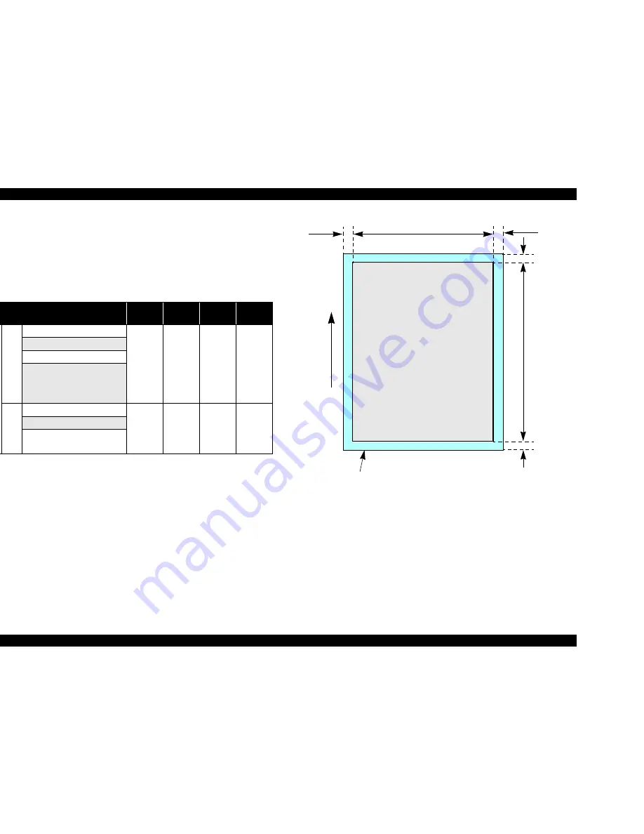
Printable area
For paper width (PW) and paper length (PL), refer to
“1.2.1.4 Paper Support ”
(p.12)
.
Refer to the following table. As for each overhang area, refer to
Figure 1-4
(p.16)
.
Figure 1-4. Printable area for Cut sheet (border-free printing)
Table 1-11. Applicable paper/Printing area
Paper type
Left
Overhang
Right
Overhang
Top
Overhang
Bottom
Overhang
E
x
cl
u
si
v
e pa
pe
r
Sty
lu
s C
X
35
00
/C
X
3
60
0/
C
X
36
50/
C
X
4
5
0
0
Photo Paper
2.5 mm
(0.09")
2.5 mm
(0.09")
3 mm
(0.12")
5 mm
(0.2")
Matte Paper Heavy Weight
DURABrite Photo Paper
Premium Semigloss Photo Paper
Sty
lus
C
X
46
00
Glossy Photo Paper
2.5 mm
(0.09")
2.5 mm
(0.09")
3 mm
(0.12")
5 mm
(0.2")
Matte Paper Heavy Weight
DURABrite Ink Glossy Photo
Paper
Paper size
LO
RO
PW
TO
BO
Paper Feed Direction
PL
Printable area
Содержание Stylus CX3500 Series
Страница 1: ...EPSON STYLUSCX3500 CX3650 CX3600 CX4500 CX4600 Color Inkjet Printer SEOT04 004 SERVICE MANUAL ...
Страница 8: ...C H A P T E R PRODUCTDESCRIPTION ...
Страница 52: ...C H A P T E R OPERATINGPRINCIPLES ...
Страница 79: ...C H A P T E R TROUBLESHOOTING ...
Страница 113: ...C H A P T E R DISASSEMBLYANDASSEMBLY ...
Страница 161: ...C H A P T E R ADJUSTMENT ...
Страница 174: ...C H A P T E R MAINTENANCE ...
Страница 181: ...C H A P T E R APPENDIX ...
Страница 200: ......
Страница 201: ......
Страница 202: ......
Страница 203: ......
Страница 204: ......
Страница 205: ......
Страница 206: ......


