


Chapter2 Operating Principles
Rev.A
2-17
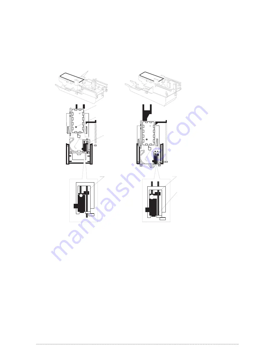
2.1.1.4.2 Cap Mechanism
In the cap mechanism, in order to prevent ink from being thickened on the head surface, it is controlled
that the head surface stays adherent to the rubber frame of the cap surface when the power is off.
The absorber is spread in the cap and can hold a certain amount of ink which is absorbed from the
head without draining it to the waste ink pad. Also, in the bottom of absorber, there are two valves in order
to control adhesion of head and cap surface, and one exit to drain ink to the waste ink pad.
If the carriage is out of HP(in this case, in the printable area or paper feed position), the valves on the
cap mechanism stays in the position A in the figure above and are always closed. In this condition,
the carriage collides with flag, actual ink absorption and slight ink absorption are performed.
Also, by moving the carriage to further right side and colliding the flag for opening the valves with
the frame, negative pressure is released in the state that head surface and cap are adhered. This
makes it possible for ink on the nozzle plate surface to be ready for leaving from the cap in the stable
condition.
A
B
Flag for Carriage
Ink Eject Valve
Negative pressure
release valve
Valve
Close state
Release state
Flag for frame
Head surface and
cap are adhered
each other.
Actual and false
absorptions.
Ink absorption in
the cap.
During cleaning, initial ink
charge, and right flushing.etc.
During left flushing and paper
feeding,etc.
Figure 2-16. Cap Mechanism Operation Principle
Содержание Stylus Color 400
Страница 1: ...EPSON COLOR INK JET PRINTER EPSON Stylus Color 400 SERVICE MANUAL SEIKO EPSON CORPORATION 4007366 ...
Страница 5: ...REVISION SHEET Revision Issued Data Contents Rev A February18 1997 First issue ...
Страница 21: ...Chapter1 Product Description Rev A 1 14 Color Printing color ESC r ESC r EEPROM control EEPROM control ESC ...
Страница 104: ...EPSON Stylus Color 400 Service Manual Rev A 4 10 Screen 1 Screen 2 Screen 3 Screen 4 Screen 5 Screen 6 ...
Страница 121: ...Chapter 6 Maintenance 6 1 OVERVIEW 6 1 6 1 1 Cleaning 6 1 6 1 2 Service Maintenance 6 1 6 1 3 Lubrication 6 2 ...
Страница 126: ...Chapter 6 Maintenance Rev A 6 5 No 1 No 2 10mm 2mm 2mm No 3 No 11 GEAR 34 ...
Страница 128: ...Chapter 6 Maintenance Rev A 6 7 No 8 HOLDER PULLEY DRIVEN No 9 No 10 HOPPER ASSEMBLY FRAME ASF ...
Страница 137: ...Appendix Rev A A 8 A 4 Circuit Board Component Layouts Figure A 2 C206 Main Board Component Layout ...
Страница 138: ...EPSON Stylus Color400 Service Manual Rev A A 9 Figure A 3 C206 PSB Board Component Layout ...
Страница 139: ...Appendix Rev A A 10 Figure A 4 C206 PSE Board Component Layout ...
Страница 140: ...EPSON Stylus Color400 Service Manual Rev A A 11 Figure A 5 C206 PNL Component Layout ...
Страница 141: ...Appendix Rev A A 12 A 5 Exploded Diagrams Figure A 6 Stylus Color 400 Exploded Diagram 1 ...
Страница 142: ...EPSON Stylus Color400 Service Manual Rev A A 13 Figure A 7 Stylus Color 400 Exploded Diagram 2 ...
Страница 143: ...Appendix Rev A A 14 Figure A 8 Stylus Color 400 Exploded Diagram 3 ...
Страница 145: ...EPSON SEIKO EPSON CORPORATION ...


