


Chapter 5 Troubleshooting
Rev.A
5-14
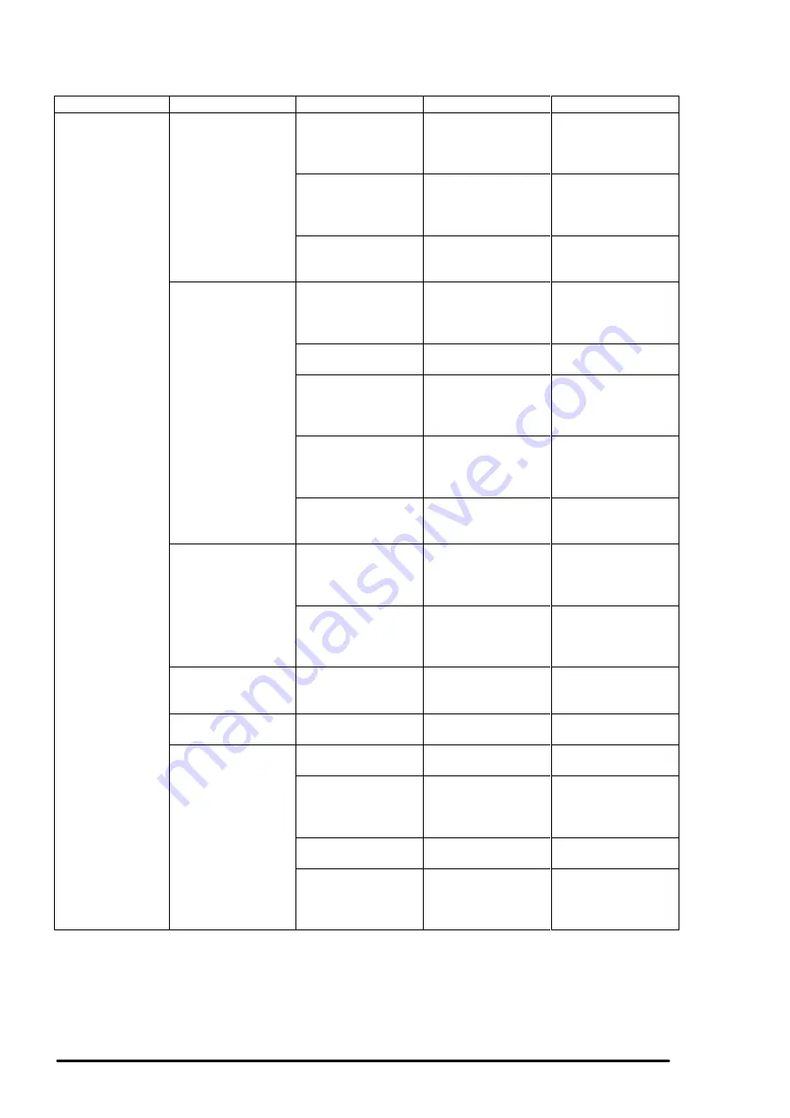
Symptom
Condition
Cause
Check-point
Solution
Abnormal printing Only a particular dot
causes abnormal
printing.
Print head surface is
not clean.
(dot missing)
Perform the cleaning
operation several
times and check
printing.
Perform the
cleaning.
The head unit is
defective.
Perform the cleaning
operation several
times and check
printing.
If condition does not
improve even after
the cleaning, replace
the head.
Capping absorber is
touching the head
surface.
Check the head
absorber visually.
Replace the head
absorber if it is
deformed.
A dot is not printed
occasionally.
Print head surface
is not clean.
(dot-missing)
Perform the cleaning
operation several
times and check
printing.
Perform the
cleaning.
The head FFC is
disconnected inside.
Check the FFC by
using a tester.
Replace the head
FFC.
The head FFC is out
of connection.
Check if the head
FFC on the board or
carriage is
connected surely.
Connect the FFC
properly.
The head unit is
detective.
Perform the cleaning
operation several
times and check
printing.
If condition does not
improve even after
the cleaning, replace
the head.
I/C is defective.
Install the new I/C
and perform self-
test.
Replace I/C.
Black specks or
dots.
The head FFC is out
of connection.
Check if the head
FFC on the board or
carriage is
connected surely.
Connect the FFC
properly.
The head unit is
detective.
Check connection
with the head FFC.
Replace the head if
there is no
connection problem
with the FFC.
A vertical line is not
aligned.
Bi-directional
alignment is not
adjusted.
Perform Bi-D
adjustment.
Refer to Chapter4.
White line appears
in the image data.
Head angle is not
correct.
Perform head angle
adjustment.
Refer to Chapter4.
Platen gap is not
correct.
Perform platen gap
adjustment.
Refer to Chapter4.
Dot shooting
direction is tilted
because head
surface is not clean
Perform the cleaning
operation several
times and check
printing.
Perform the
cleaning operation.
I/C is defective.
Install a new I/C and
perform the self-test.
Replace I/C.
Head unit is
defective.
Perform the cleaning
operation several
times and check
printing.
Replace the head
unit.
Table 5-10. Repair of the Printer Mechanism (Continued.)
Содержание Stylus Color 400
Страница 1: ...EPSON COLOR INK JET PRINTER EPSON Stylus Color 400 SERVICE MANUAL SEIKO EPSON CORPORATION 4007366 ...
Страница 5: ...REVISION SHEET Revision Issued Data Contents Rev A February18 1997 First issue ...
Страница 21: ...Chapter1 Product Description Rev A 1 14 Color Printing color ESC r ESC r EEPROM control EEPROM control ESC ...
Страница 104: ...EPSON Stylus Color 400 Service Manual Rev A 4 10 Screen 1 Screen 2 Screen 3 Screen 4 Screen 5 Screen 6 ...
Страница 121: ...Chapter 6 Maintenance 6 1 OVERVIEW 6 1 6 1 1 Cleaning 6 1 6 1 2 Service Maintenance 6 1 6 1 3 Lubrication 6 2 ...
Страница 126: ...Chapter 6 Maintenance Rev A 6 5 No 1 No 2 10mm 2mm 2mm No 3 No 11 GEAR 34 ...
Страница 128: ...Chapter 6 Maintenance Rev A 6 7 No 8 HOLDER PULLEY DRIVEN No 9 No 10 HOPPER ASSEMBLY FRAME ASF ...
Страница 137: ...Appendix Rev A A 8 A 4 Circuit Board Component Layouts Figure A 2 C206 Main Board Component Layout ...
Страница 138: ...EPSON Stylus Color400 Service Manual Rev A A 9 Figure A 3 C206 PSB Board Component Layout ...
Страница 139: ...Appendix Rev A A 10 Figure A 4 C206 PSE Board Component Layout ...
Страница 140: ...EPSON Stylus Color400 Service Manual Rev A A 11 Figure A 5 C206 PNL Component Layout ...
Страница 141: ...Appendix Rev A A 12 A 5 Exploded Diagrams Figure A 6 Stylus Color 400 Exploded Diagram 1 ...
Страница 142: ...EPSON Stylus Color400 Service Manual Rev A A 13 Figure A 7 Stylus Color 400 Exploded Diagram 2 ...
Страница 143: ...Appendix Rev A A 14 Figure A 8 Stylus Color 400 Exploded Diagram 3 ...
Страница 145: ...EPSON SEIKO EPSON CORPORATION ...


