
4. Connections
14
Seiko Epson Corporation
S5U1C17001H2 User Manual
(ICDmini Ver2.0)
4. Connections
4.1
Connecting the Target System
4.1.1
Target Interface Connector
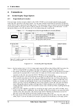
The 4-pin target interface connector (black) on the S5U1C17001H is used to input/output the debug signals
from/to the S1C processor on the target system. Use the target interface cable attached to the S5U1C17001H to
connect between this connector and the target system. T his connection is always required to perform debugging.
T he pin assignment of the 4-pin connector (black) on the S5U1C17001H is shown in the table below. For the
debug pin numbers on the S1C processor, refer to the technical manual of each model.
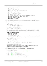
Table 4.1.1.1 Pin Assignment of the Target Interface Connector (Black)
No.
Pin name
I/O
Pin function
1
DCLK
I
Clock signal input pin for debugging
2
GND
–
Power supply GND pin
3
DSIO
I/O
Serial transfer I/O pin for debugging
4 3 2 1
4
DST2
I
Debug status signal input pin
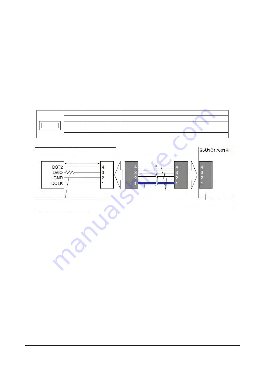
Figure 4.1.1.1 Connecting the Target System
Notes:
Set the interface level (3.3 V/1.8 V/target input) using the DIP switches SW4 and SW5, and select the
CPU Core using the SW1 according to the target system before connecting the target system.
The signals connected to the S5U1C17001H are very high-speed signals, so the connector on the target
system must be mounted within 5 cm from the S1C processor. If there is more distance between the
connector and the S1C processor, the S5U1C17001H may not work properly.
When wiring the S1C processor to the target connector for connecting the S5U1C17001H, insert a
33
resistor in series between the S1C processor DSIO pin and the connector. This resistor must be
placed as close to the S1C processor as possible. Although the system can operate without this 33
resistor, we recommend inserting this resistor to prevent malfunctions. The other pins are connected
directly. A low-level input to the DSIO pin issues a forced break to set the S1C processor into debug
mode. Although this signal is pulled up through about 100 k
internally, when not debugging, we
recommend either removing the 33
resistor to reduce noise and other problems or pulling this line up
to the VDD level.
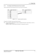
Be sure to use the supplied 4-pin cable for connecting the target system to the S5U1C17001H. Using
another cable may cause a malfunction. If use of another cable is unavoidable, do not extend the target
interface cable, and connect the cable directly to the S5U1C17001H so that the distance to the S1C
processor on the target system is as short as possible (no more than 20 cm).
The 4-pin connector does not have a projection for preventing reverse insertion. Check the cable color
(blue) of pin 1 to be sure the insertion of connector is proper when connecting it to the target system.
Target system
Target interface cable
S1C processor
Within 5 cm
Target interface connector
Place a 33
resistor in series at a location
as close to
the S1C processor as possible.
Blue
White


