

3. Name and Function of Each Part
10
Seiko Epson Corporation
S5U1C17001H2 User Manual
(ICDmini Ver2.0)
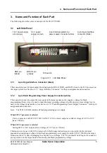
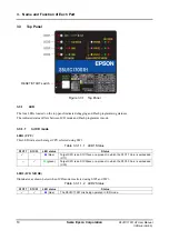
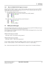
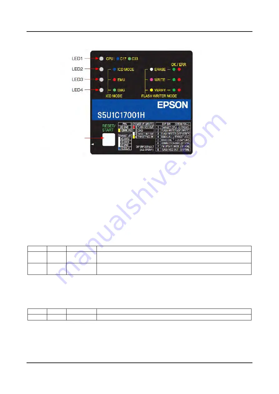
3.3 Top
Panel
Figure 3.3.1 Top Panel
3.3.1 LED
The four LEDs located on the top panel indicate debugging and Flash programming statuses.
The indicated status differs between ICD mode and Flash programmer mode.
3.3.1.1
In ICD mode
LED1 (CPU)
This LED indicates the target CPU selected using SW1.
Table 3.3.1.1.1 LED1 Status
S1C17 S1C33 LED
status
Status
–
(blue)
Target CPU is an S1C17xxx or a product in which the S1C17 Core is embedded
(C17).
–
(green)
Target CPU is an S1C33xxx or a product in which the S1C33 Core is embedded
(C33).
LED2 (ICD MODE)
Illuminates as shown below when ICD mode is selected using SW2 and SW3.
Table 3.3.1.1.2 LED2 Status
S1C17 S1C33 LED
status
Status
(blue)
The S5U1C17001H is being operated in ICD mode.
RESET/START switch


