5. Connection Example with FreeScale iMX21
18
EPSON
S1R72V17 CPU Connection Guide
(Rev. 1.0)
5.3 Checking
S1R72V17
AC
Spec and iMX21 Bus Cycle
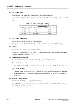
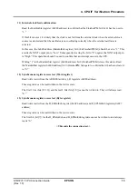
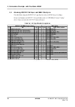
The table below compares S1R72V17 AC specification values to iMX21 bus cycle settings.
For more information on S1R72V17 AC specification, refer to “CPU/DMA IF Access Timing”
(8.4.3.1 Basic Cycle) in the
S1R72V17 Technical Manual
.
Table 5-2 AC Specification Comparison
Code
Item
min
max Cycles
unit
iMX21 setting register
tcas Address setup time
6
-
2
HCLK RWA, OEA
tcah Address hold time (from strobe negation)
6
-
1
HCLK RWN, OEN
tsah Address hold time (from strobe assertion)
55
-
6
HCLK WSC-(RWA, OEA)
tccs XCS setup time
6
-
2
HCLK RWA, OEA
tcch XCS hold time
6
-
1
HCLK RWN, OEN
trcy Read cycle
80
-
8
HCLK WSC
tras Read strobe assert time
40
-
5
HCLK WSC-(OEA+OEN)
trng Read strobe negate time
25
-
3
HCLK OEA+OEN
trbd Read data output start time
1
-
-
trdf Read data confirmation time
-
35
5
HCLK WSC-(OEA+OEN)
trdh Read data hold time
3
-
-
trbh Read data output delay time
-
9
-
twcy Write cycle
80
-
8
HCLK WSC
twas Write strobe assert time
40
-
5
HCLK WSC-(RWA+RWN)
twng Write strobe negate time
25
-
3
HCLK RWA+RWN
twbs Write byte enable setup time
6
-
2
HCLK RWA
twbh Write byte enable hold time
6
-
1
HCLK RWN
twds Write data setup time
0
-
1.5
HCLK RWA - 0.5HCLK (data output start)
twdh Write data hold time
0
-
1
HCLK RWN
tdrn XDREQ negate delay time
-
35
-
tdaa XDREQ setup time
6
-
-
tdan XDREQ hold time
6
-
-
(
C
L
=30pf )
1HCLK=11.36ns (88MHz)
S1R72V17 CPU/DMA IF access timing
iMX21 setting


