background image

EPSON Stylus Photo R200/R210

Revision A

DISASSEMBLY AND ASSEMBLY

Disassembly

45

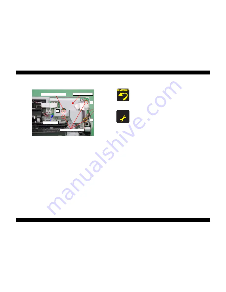
2.3.7  Board, Main removal

o

External View

Figure 2-12.  Board, Main removal

o

Pars/Units which should be removed before removing "Board, Main"

Paper Support Assy./Housing (left/right)/Housing (frame)

/ASF Unit

o

Disassembly Procedure

1.

Disconnect all connector cables from "Board, Main".

CN2

: Power supply connector cable

CN4

: Panel board connector cable

CN5

: CR motor connector cable

CN6

: PF motor connector cable

CN7

: Head FFC

CN8

: Head FFC

CN9

: PE sensor connector cable

CN10

: Interface board connector cable

CN11

: CDR tray sensor cable

CN13

: APG motor connecor cable

CN14

: PG sensor cable

CN15

: CSIC/CR encoder /PW sensor FFC

2.

Remove the screws (x4) for securing "Board, Main"with the order in figure, and 
remove "Board, Main".

3.

Remove "Shield Plate, M/B" from "Board, M/B".

1

2

3

C.B.S 3x10 (5‑7kgf/cm)

4

C.B.S 3x6 (5‑7kgf/cm)

Board, Main

Shield Plate

,M/B

o

When reinstalling "Board, Main",

n

Make sure that all cables/FFCs are correctly connected to 
the appropriciate connector of "Board, Main". 

n

Make sure to secure the screws in the order as shown in the 
figure.

A D J U S T M E N T

R E Q U I R E D

o

When having replaced "Main Board", implement the 
adjustment in the following order. (Refer to Chapter 3 
"ADJUSTMENT")

n

When possible to read data from the old board

1.

EEPROM data copy

n

When impossible to read from the old board

1.

Replace "Waste Ink Pads" with new one.
(To count the amount of the waste ink)

2.

Market Setting

3.

USB ID Input

4.

Waste Ink Pad Counter

5.

Head ID Input

6.

First Dot Adjustment

7.

PW Sensor Adjustment

8.

Head Angular Adjustment

9.

Bi-D Adjustment

10. Offset Input for CR Motor Calorific Limitation

Содержание R200 - Stylus Photo Color Inkjet Printer

Страница 1: ...EPSON StylusPhotoR200 R210 Color Inkjet Printer SEIJ03014 SERVICE MANUAL ...

Страница 2: ...er should any errors be detected SEIKO EPSON would greatly appreciate being informed of them o The above not withstanding SEIKO EPSON CORPORATION can assume no responsibility for any errors in this manual or the consequences thereof EPSON is a registered trademark of SEIKO EPSON CORPORATION General Notice Other product names used herein are for identification purpose only and may be trademarks or ...

Страница 3: ...E MUST BE CONNECTED USE EXTREME CAUTION IN WORKING ON POWER SUPPLY AND OTHER ELECTRONIC COMPONENTS 4 WHEN DISASSEMBLING OR ASSEMBLING A PRODUCT MAKE SURE TO WEAR GLOVES TO AVOID INJURIER FROM METAL PARTS WITH SHARP EDGES WARNING 1 REPAIRS ON EPSON PRODUCT SHOULD BE PERFORMED ONLY BY AN EPSON CERTIFIED REPAIR TECHNICIAN 2 MAKE CERTAIN THAT THE SOURCE VOLTAGES IS THE SAME AS THE RATED VOLTAGE LISTED...

Страница 4: ...s manual either to provide additional information on a specific topic or to warn of possible danger present during a procedure or an action Be aware of all symbols when they are used and always read NOTE CAUTION or WARNING messages Indicates an operating or maintenance procedure practice or condition that is necessary to keep the product s quality Indicates an operating or maintenance procedure pr...

Страница 5: ...Revision Status Revision Issued Date Description A January 29 2004 First Release ...

Страница 6: ...Printer Mechanism Housing lower removal 57 2 3 13 Power Supply Unit removal 61 2 3 14 CDR Guide Assy removal 62 2 3 15 Ink System Unit removal 64 2 3 16 Paper Guide Front Roller EJ Assy removal 67 2 3 17 PF Motor removal 71 Chapter 3 ADJUSTMENT 3 1 Adjustment Items and Overview 73 3 1 1 Servicing Adjustment Item List 73 3 1 2 Replacement Part Based Adjustment Priorities 77 3 2 Adjustment by using ...

Страница 7: ...C H A P T E R TROUBLESHOOTING ...

Страница 8: ...ration of the motor or not the resistance values cannot be used to judge the abnormality However it is difficult to judge accurately if it is not clear replace the motor START UNIT LEVEL TROUBLESHOOTING UNIT REPAIR ASSEMBLY AND ADJUSTMENT END Table 1 1 Motor Coil Resistance Motor Location Check Point Resistance PF Motor Same as ASF Pump Motor CN6 Pin 1 and 3 Pin 2 and 4 3 0W 10 25 C phase Table 1 ...

Страница 9: ... loading feeding and the ink absorption operation As for the screen shot in STM3 message it s used screen shot of Stylus Photo R300 310 as a substitute for that of Stylus Photo R200 210 Table 1 3 LED Indication and STM3 Printer status LED indication STM3 message Condition for error detection Power Paper Ink Communication Error This error is detected when the printer cannot communicate with the PC ...

Страница 10: ...displayed on STM3 However the Head Cleaning operation may not be performed due to the Ink Low condition This error is detected when the ink consumption reaches about 90 Note When the Ink Low Condition is detected the Maintenance LED will blink The printer will continue to keep this LED status even if a new Ink Cartridge is installed in the Ink Cartridge replacement position However this LED status...

Страница 11: ...Ink Cartridge to protect the Print Head from printing operation Paper Out Error On This error is detected when the top of paper cannot be detected with the PE Sensor in a paper loading Paper Jam Error Including CD DVD Blink This error is detected when 1 The end of paper cannot be correctly detected with the PE Sensor in a paper loading 2 The rear of CD DVD cannot be correctly detected with the Sta...

Страница 12: ...when the value of the Waste Ink Pad Counter A set in EEPROM reaches its limit Variable between 20000 and 46750 points CD DVD Guide Error Blink 2 Fast Blink This error is detected when 1 Paper is present in ASF Assy and CDR Guide Assy is open while receiving print data 2 CDR Guide Assy opens while printing 3 CDR Guide Assy is open while receiving ASF paper feed data 4 Attempting to replace the ink ...

Страница 13: ... on 0 1sec off Alternant Blink 1 Same as Blink Alternant Blink 2 Same as Blink CD DVD Tray Error On This error is detected when CD DVD Tray cannot be detected while CD DVD printing Fatal error Off Fast Blink Fast Blink This error is detected when 1 Carriage Unit cannot move correctly by the external force in each operation 2 PF Motor cannot rotate correctly while PF Motor operates Table 1 3 LED In...

Страница 14: ...e necessary operation by referring to Chapter 2 ASSEMBLY DISASSEMBLY Table 1 4 Check Points for Communication Error to Each Phenomenon Occurrence Timing Position of CR Phenomenon Detail Faulty Part Part Name Check Point Remedy At power on Anywhere When turning on the power the printer does not operate at all Power Supply Board 1 Check if Power Supply Board Cable is connected to the CN2 on Main Boa...

Страница 15: ...stment Program At power on Anywhere The printer does not perform the Ink Replacement Cleaning and the error is displayed on LED and STM3 Ink Cartridge 1 Check if the Ink Cartridge is normal by installing it in another printer 1 Replace the Ink Cartridge with a new one The printer does not perform any print operation and the error is displayed on LED and STM3 Ink Cartridge 1 Check if ink still rema...

Страница 16: ...g 0 143 in Clutch Mechanism has not come off 2 Check if Clutch has not come off from the dowel of Shaft LD Roller 3 Check if Clutch Tooth is not damaged 4 Check if Clutch is not damaged 1 Reassemble Extension Spring 0 143 in Clutch Mechanism 2 Reassemble the round portion of Clutch on the dowel of Shaft LD Roller 3 Replace Holder Shaft LD Roller with a new one 4 Replace Holder Shaft LD Roller with...

Страница 17: ...lso does not rotate at all PF Motor 1 Check if PF Connector Cable is connected to CN6 on Main Board 2 Check if the coil resistance of PF Motor is approximately 3 0W with a tester Refer to Table 1 1 3 Check if PF Motor Connector Cable is damaged 1 Connect PF Motor Connector Cable to CN6 on Main Board 2 Replace PF Motor with a new one 3 Replace PF Motor with a new one At operation Holder Shaft LD Ro...

Страница 18: ...n Main Board 2 Replace PF Motor with a new one 3 Replace PF Motor with a new one Paper feeding operation is performed normally but paper is not sent into the printer ASF Assy 1 Check if Roller Retard Assy operates properly while feeding paper 1 Reassemble Extension Spring 0 45 located the under side of Roller Retard Assy PE Sensor 1 Check if Torsion Spring 0 22 is not unfastened from PE Sensor Lev...

Страница 19: ...le feeding paper 1 Reassemble Extension Spring 0 45 back of Roller Retard Assy The leading edge of paper does not go through between Roller EJ Assy and Star Wheels Frame EJ Assy 1 Check if Star Wheels have not come off 2 Check if Frame EJ Assy is correctly assembled 3 Check if Frame EJ Assy is not transformed toward downward 1 Reassemble Star Wheels correctly 2 Reassemble Frame EJ Assy correctly 3...

Страница 20: ...nsion Spring 0 22 has come off or PE Sensor is not set in the correct position However in the next operation a Paper Jam Error will be detected since PE Sensor Lever will maintain the High signal status There some cases where the jammed paper may damage Print Head by contacting the surface of Print Head nozzle when a Paper Jam Error occurs in each operation Table 1 7 Check Points for Paper Jam Err...

Страница 21: ...int of Housing Middle with Star Wheel CDR Sensor is not cracked 1 Replace Housing Middle with a new one Star Wheel CDR Sensor 1 Check if Star Wheel CDR Sensor is connected to CN11 on Main Board 2 Check if Star Wheel CDR Sensor is not damaged 3 Check if Star Wheel CDR Sensor cable is not cut off 1 Connect Star Wheel CDR Sensor to CN11 on Main Board 2 Replace Star Wheel CDR Sensor with a new one 3 R...

Страница 22: ...Check if the contact point of CDR Tray with CDR Tray Sensor is not cracked 1 Replace CDR Tray with a new one CDR Tray Sensor 1 Check if CDR Tray Sensor is connected to CN11 on Main Board 2 Check if CDR Tray Sensor is not damaged 3 Check if CDR Tray Sensor Connector Cable is not cut off 1 Connect CDR Tray Sensor to CN11 on Main Board 2 Replace CDR Tray Sensor with a new one 3 Replace CDR Tray Senso...

Страница 23: ...or is approximately 3 0W using a tester Refer to Table 1 1 3 Check if PF Motor Connector Cable is not damaged 1 Connect PF Motor Connector Cable to CN6 on Main Board 2 Replace PF Motor with a new one 3 Replace PF Motor with a new one Ink System 1 Check if Compression Spring 2 36 of Lever Change has not come off 1 Replace Ink System with a new one Carriage Unit strikes on Paper Guide Upper which ha...

Страница 24: ... Occurrence Timing Position of CR Phenomenon Detail Faulty Part Part Name Check Point Remedy Any time Anywhere Abnormal sound is heard in spite of the normal print operation at the first power on or some other time Carriage Unit 1 Check if there is enough grease on CR Guide Shaft 1 Wipe the remaining grease off CR Guide Shaft and reapply some grease Ink System 1 Check if Lever Change moves smoothl...

Страница 25: ...ent colors of ink mix together Phenomenon 4 When the printer is performing the Cleaning task the ink is drained into Waste Ink Pad However some missing dots occurs while printing Phenomenon 5 When the printer is performing the Cleaning task the ink is drained into Waste Ink Pad However missing dot occurs and the points where it occurs varies in every movement of the Cleaning Ink System 1 Check if ...

Страница 26: ...nated awfully 2 Securely connect Head FFC to Main Board or the board on Print Head 3 Replace Head FFC with a new one 4 Perform Head Cleaning and check the Nozzle Check Pattern If the problem is not solved replace Print Head with a new one Banding phenomenon occurs in a direction perpendicular to Carriage Unit movement getting uneven print density Note If the problem is not solved replace CR Motor ...

Страница 27: ...amaged 3 Check if Spur Gear 37 242 is not damaged or broken 1 Clean the surface of PF Roller 2 Replace Printer Mechanism with a new one 3 Replace Printer Mechanism with a new one Printer Driver and Special Paper 1 Check if appropriate paper is used in accordance with the Printer Driver settings 1 Use the appropriate type of paper in accordance with the Printer Driver Print Head 1 Check if Print He...

Страница 28: ...Shaft LD Roller 1 Check if any paper dust has not adhered to the surface of LD Roller 1 Remove the dust by using a soft bruch or soft cloth moistened with alcohol If the problem is not solved replace Holder Shaft LD Roller with a new one The print is light and thin Printer Driver and Special Paper 1 Check if appropriate paper is used in accordance with the Printer Driver settings 1 Use the appropr...

Страница 29: ...sy 1 Clean the ink adhesion on Roller EJ Assy with a soft cloth Paper Guide Upper 1 Check if there is any ink adhesion on Paper Guide Upper 1 Clean the ink adhesion on Paper Guide Upper with a soft cloth PF Roller 1 Check if there is any ink adhesion on PF Roller 1 Clean the ink adhesion on PF Roller with a soft cloth Ink System 1 Check if the wiping operation has been performed correctly 1 Replac...

Страница 30: ...C H A P T E R DISASSEMBLYANDASSEMBLY ...

Страница 31: ...ly and reassembly to avoid injury from sharp metal edges n To protect sensitive microprocessors and circuitry use static discharge equipment such as anti static wrist straps when accessing internal components n Never touch the ink or wasted ink with bare hands If ink comes into contact with your skin wash it off with soap and water immediately If you have a skin irritation consult a physician n Wh...

Страница 32: ...ecked o Not necessary On line Test Is the printing successful o Checked o Not necessary Print Head Is ink discharged normally from all the nozzles o Checked o Not necessary Carriage Mechanism Does it move smoothly o Checked o Not necessary Is there any abnormal noise during its operation o Checked o Not necessary Is there any dirt or foreign objects on the CR Guide Shaft o Checked o Not necessary ...

Страница 33: ...on Is it the latest version Version o Checked o Not necessary Packing Ink Cartridge Are the ink cartridges installed correctly o Checked o Not necessary Protective Materials Have all relevant protective materials been attached to the printer o Checked o Not necessary Others Attachments Accessories Have all of the accessories been included in the package o Checked o Not necessary Table 2 2 Service ...

Страница 34: ...sing Lower Manage the standard values for installation See below First remove Support Plate Frame Main Then remove Roller PF Unit Roller EJ Assy and Paper Guide Front Make sure to manage Waste Ink Tube Be careful with the interconnection of Star Wheel CDR Sensor connector cable Assemble Cam CR Left while gearing with the APG gear n Management of the reference position for installation Reason Accur...

Страница 35: ...it may be deformed and cause the defective print operation Support for Service Hold the opposite side of the components securely when installing them 3 CDR Guide Assy n Management of the level accuracy of CDR Guide Assy Reason Deformation of CDR Guide Assy may cause the defective print Support for Service Disassemble assemble carefully CDR Guide Assy o How to secure the quality for reassembled pro...

Страница 36: ...d removal 2 3 7 P 45 APG Unit removal 2 3 9 P 49 CR Unit removal 2 3 11 P 51 PF Motor removal 2 3 17 P 71 CDR Guide Assy removal 2 3 14 P 62 Ink System Unit removal 2 3 15 P 64 Paper Guide Front Roller EJ Assy removal 2 3 16 P 67 Printer Mechanism Housing lower removal 2 3 12 P 57 P S Board Unit removal 2 3 13 P 61 Paper Guide Upper removal 2 3 10 P 50 Print Head removal 2 3 5 P 43 Porous Pad Pape...

Страница 37: ...y to ASF frame n Housing left right removal 1 Remove the screw x1 x1 for securing the housing left right 2 Release the hook x1 forward by using screwdriver 3 Release the hook x1 by inserting minus screwdriver between the housing lower and the housing left right 4 Release Carriage Lock with the tweezers or alike then move Carriage unit to the centre of the printer 5 Remove the housing left right by...

Страница 38: ...r assy n Do not injure your hand by the tool such as the screwdrive n Do not tilt the printer too much because ink may flow if the cap is not covered by the print head o When reinstalling paper support assy housing left right stacker assy n Make sure that there is no clearance beteen the housing left right and the housing frame n Make sure that the right side of the stacker assy is set to the damp...

Страница 39: ...he hooks x2 for securing the front side of the housing frame 5 Remove the housing frame upward n Panel assy removal 1 Release two hooks for securing the panel assy to the housing frame n Panel board removal 1 Remove the panel board upward 1 Backside Cover Ink Tube Left front side Right front side C B S 3x8 5 7kgf cm 2 4 4 4 5 5 CN4 Panel FFC 3 Panel assy Housing Frame C B P 2 5x8 3 5kgf cm o When ...

Страница 40: ...release the cables 4 Remove the ASF unit backward 5 Open Hopper and then remove Compression Spring 2 51 6 Bow slightly down Paper Return Lever and release the dowels x2 on the both sides in the order of and remove Paper Return Lever 7 Remove the screws x2 for securing Support Plate Frame ASF 8 Release the hooks x2 for securing Extension Spring 0 45 and remove Roller Retard Assy CN11 CN14 Board Mai...

Страница 41: ... move smoothly n Do not touch the cork of Hopper o When reinstalling ASF Unit n Install Compression Spring 2 51 on Hopper then check if Hopper moves smoothly n Screw in the order as shown in the figure n Make sure that there is no gap between ASF Unit and Frame Main Torsion Spring 6 45 A D J U S T M E N T R E Q U I R E D o When having replaced ASF Unit apply G 46 grease to the specified points in ...

Страница 42: ... Then remove Timing Belt from the pinion gear of CR Motor 5 Remove the screws x2 which secure CR Motor and remove CR Motor Puller Driven Timing Belt CR Motor C C 3x4 3 5 4 5kgf cm 1 2 CN5 CR Motor Hook Backside C A U T I O N Do not damage the pinion gear when removing CR Motor o When reinstalling the CR Motor n Make sure to screw CR Motor in the order as shown in the figure n Make sure that there ...

Страница 43: ...ews x2 for securing Print Head with Phillips screwdriver No 1 7 Disconnect Cable Head from the connector CN7 8 of Print Head while slightly lifting Print Head and remove Print Head Hooks Holder IC C B B P2 2 5x8 3 5kgf cm Cable Head Print Head C B P 2 5x6 3 5kgf cm Holder FFC Hooks C A U T I O N Do not touch and or damage the nozzle surface of Print Head when handling it o When reinstalling the Pr...

Страница 44: ...right sides of Porous Pad Paper Guide Front Support at the marks and install it to Paper Guide Front Make sure that the slit engages with the rib located on the side of Paper Guide Front so that they will fit securely n Apply ThreeBond 1401 to the 6 points shown in the figure above n Install Porous Pad Paper Guide Front in piles Put it under the rib and check if it is securely fit Adjust the clear...

Страница 45: ...rd Main with the order in figure and remove Board Main 3 Remove Shield Plate M B from Board M B 1 2 3 C B S 3x10 5 7kgf cm 4 C B S 3x6 5 7kgf cm Board Main Shield Plate M B o When reinstalling Board Main n Make sure that all cables FFCs are correctly connected to the appropriciate connector of Board Main n Make sure to secure the screws in the order as shown in the figure A D J U S T M E N T R E Q...

Страница 46: ...or securing Holder Shaft Unit 5 Release the Head FFC with Shield Plate FFC from Holder Shaft Unit 6 Release the hooks x2 with the tweezers or alike while pulling Holder Shaft Unit upward and release the dowel x1 from Ink System Frame 7 Looking at the printer from its back side press down Paper Guide Upper on the left and release PE Sensor Lever from the slot Then remove Holder Shaft Assy by slidin...

Страница 47: ...ler 3 Remove LD Roller from Shaft LD Roller Paper Block Spur Gear 36 8 Clutch Extension Spring 0 143 Shaft LD Roller Dowel PE Sensor Board Hook Torsion Spring 0 22 Lever Sensor PE Holder Shaft LD Roller LD Roller Dowel Dowel Dowel C A U T I O N Do not touch LD Roller with bare hands o When reinstalling LD Roller n Make sure to match the direction Mark indicated on Shaft LD Roller and the direction...

Страница 48: ...he straight part of Torsion Spring 137 7 is set between the two cams LD Roller o When reinstalling Holder Shaft Unit n Check if the hooks x2 the dowel and the ribs x5 of Holder Shaft Assy are correctly secured n Check if the connector cable of PE Sensor and Cable Head are installed at the correct position of Holder Shaft Assy n Do not touch LD Roller n Do not damage the teeth of Spur Gear 36 8 and...

Страница 49: ...e APG motor connector cable from the connector CN13 of Main Board 2 Remove the screw x1 for securing APG Unit and remove the APG Unit carefully C B S 3x6 6 8kgf cm APG Unit Shield Plate M B Left backside o When reassembling APG Unit n Make sure that the hooks x2 and the dowels x2 of APG Unit are securely attached to Frame Main n Check if the part indicated in the following figure is inserted in th...

Страница 50: ...rom the hook 1 each of Frame Main then pull it out to the front 4 Release the hooks 2 each for securing Paper Guide Upper x3 to upward Then release the dowels 2 each while slightly holding up Paper Guide Upper 5 Press down Paper Guide Lower and pull out Paper Guide Upper x3 to the front while stepping it aside the ribs 2 each of Frame Main Transparency Roller PF Assy Paper Guide Upper Torsion Spri...

Страница 51: ...hich has secured Fixed Spring CR Shaft Left 4 Remove the right side of CR Scale from Holder Scale Right 5 Pull out CR Scale from the back of Carriage Unit to the left Then release CR Scale from one of two hooks of Holder Scale Left first and next release Extension Spring 3 289 from the other hook 6 Remove Extension Spring 3 289 from CR Scale 7 Loosen the tension of Timing Belt by pushing Pulley Dr...

Страница 52: ...er and the leaf spring for securing Holder Scale Left 12 Remove the E ring the plain washer and the spring washer from the left side of CR Guide Shaft Then remove Holder Scale Left 13 Release Cable Head from the hooks x7 of Holder Shaft Unit 14 Slide CR Guide Shaft to the right and pull it out from Cam CR left Then remove Carriage Unit and CR Guide Shaft together 15 Pull out CR Guide Shaft from Ca...

Страница 53: ...riven removal 1 Remove Extension Spring 26 4 6 from Pulley Driven and the hook of Frame Main by using a flat blade screwdriver Then remove Extension Spring 26 46 2 Slide Pulley Driven in the direction of the arrow Then remove Frame Main from the slot n CR Encoder Sensor Board removal 1 Remove the screw which secures CR Encoder Sensor Board with Phillips screwdriver No 0 Disconnect PW Sensor FFC fr...

Страница 54: ...Guide IC by using the tweezers Then remove Lever Cartridge 3 Remove the screws x2 for securing Guide IC then release the hook with the tweezers And remove Guide IC 4 Release the hooks x2 for securing CSIC Board then push up CSIC Board from the slot located on the bottom of Carriage Unit with a flat blade screwdriver or alike Finally remove CSIC Board Hooks Cap PW Sensor PW Sensor Board Connector T...

Страница 55: ...der Holder Scale o When reinstalling Carriage Unit n Check if Timing Belt is correctly set to the installing groove of Carriage Unit n Check if Grounding Plate Head is installed to the proper position of Carriage Unit Figure 2 27 Installation Position of Grounding Plate Head o When reinstalling CR Scale n Make sure that Extension Spring 3 289 is not twisted n Make sure to pass CR Scale through the...

Страница 56: ...Left n Pulley Driven Assy o When having removed or replaced Carriage Unit or CR Guide Shaft implement the adjustment in the following order Refer to Chapter 3 ADJUSTMENT 1 PG Adjustment 2 First Dot Adjustment 3 PW Sensor Adjustment 4 Head Angular Adjustment Only Carriage Unit 5 Bi D Adjustment 6 Offset Input for CR Motor Calorific Limitation When Replace CR Guide SHaft o When having removed or rep...

Страница 57: ... of the printer 2 Remove the screws x3 for securing Paper Guide CDR 3 Remove the screws x5 for securing Printer Mechanism 4 Take off the acetate tape and release the connector of Star Wheel CDR Sensor 5 Cut off the wire band and release the connector cable 6 Release the hooks x4 for securing Printer Mechanism Then hold the both right and left upper edges of Frame Main and remove Printer Mechanism ...

Страница 58: ... Porous Pad Ink Eject Upper Support Hook o When reinstalling Printer Mechanism n For this printer Housing Lower is the standard to correctly install each part of Printer Mechanism In order to ensure the accuracy for installing it is necessary to manage the reference position for Frame Main installation in X Y and Z direction as shown in the figure below If every part is set correctly Printer Mecha...

Страница 59: ...ttom Waste Ink Pad Upper Top Waste Ink Pad Lower Bottom Cap Ink Pad Lower Small Top Waste Ink Pad Small Figure 2 34 Waste Ink Pads installation 2 n After checking Waste Ink Tube is under Waste Ink Pad Lower put the jig on the indicated points in the figure below then install Porous Pad Ink Eject Upper Support Figure 2 35 Porous Pad Ink Eject Upper Support installation Jig Porous Pad Ink Eject Uppe...

Страница 60: ...he line mark on the tube is facing to the left Also make sure that it is not twisted Figure 2 36 Installation position for Ink Tube n Make sure that Waste Ink Tube is not squashed or pressed n Check if Cap Assy moves smoothly A D J U S T M E N T R E Q U I R E D o When having replaced Waste Ink Pads with new ones implement the following adjustment Refer to Chapter 3 ADJUSTMENT n Waste Ink Pad Count...

Страница 61: ...hield Plate Upper and then remove Shield Plate Upper 4 Remove the screws x4 which secure PSB PSE Board and then remove PSB PSE Board C B P 3x10 6 8kgf cm Power Supply Unit 1 2 3 Shield Plate Upper C B S 3x6 6 8kgf cm Hooks C B S 3x6 6 8kgf cm 4 5 4 2 1 3 C B S 3x6 6 8kgf cm o When reinstalling PSB PSE Board n Make sure to screw in the order as shown in the figure o When reinstalling Shield Plate U...

Страница 62: ...h secure Support Plate Frame Main Then remove Support Plate Frame Main 3 Remove the screws x3 which secure CDR Guide Assy 4 Remove the flat washer which secure Link CDR Left Right with the tweezers Then Remove Link CDR Left Right from CDR Guide Assy 5 Release the ribs x7 which secure CDR Guide Assy then remove CDR Guide Assy through the right edge 6 Remove the screws x2 which secure CDR Guide Lowe...

Страница 63: ... that the hooks x2 of Lock Stacker are properly secured by the tension of Compression Spring 5 1 n Make sure that CDR Guide Upper is securely secured with the hooks x7 of CDR Guide Lower and there is no gap between CDR Guide Upper and CDR Guide Lower o When reinstalling CDR Guide Assy n Place the the connector cable of Star Wheel CDR Sensor on the red circle position of acetate tape n Place the th...

Страница 64: ...ecure Pump Assy and hold on Lever Change Assy and all the gears in order not to let them drop then remove Cap Assy and Pump Assy together 6 Remove Combination Gear 20 82 24 Spur Gear 27 2 Lever Change Assy and Combination Gear 27 2 19 2 from Pump Assy 7 Remove Spur Gear 25 6 from Lever Change 8 Remove Compression Spring 2 36 from the dowel of Lever Change 1 2 Support Plate Frame Main C B P 3x8 5 7...

Страница 65: ...us Slider Cap from the hook of Slider Cap Extension Spring 0 788 Extension Spring 0 441 Hooks Frame Cap Slider Cap Shaft Porous Pad Slider Cap Hook Lever Lock Slider o When reinstalling Lever Lock Slider n Check if it works properly working with Slider Cap o When reinstalling Ink System n Make sure that the ink tube is correctly connected to the point of Frame Cap shown in the figure below If it i...

Страница 66: ...hly n Make sure that the ink tube is not squashed or pressed n Install the ink tube to the grooves x2 at the bottom surface of Cap Frame Figure 2 44 Installation point for the ink tube o When reinstalling Ink System n Check if Pump Assy is correctly secured n Do not let Lever Change Combination Gear 27 2 19 2 Spur Gear 27 2 and Combination Gear 20 82 24 drop and break them ...

Страница 67: ...en remove Spur Gear 41 48 5 Remove Compression Spring 1 27 and Holder Idle Roller together with PF Timing Belt 6 Move back Carriage Unit to the home position and then remove Frame EJ Assy in the direction of the arrow also in the order indicated in the figure 7 Remove the flat washer which secures Link EJ Left then Slide Link EJ Left to the right 8 Remove Extension Spring Push Up Plate Left from t...

Страница 68: ...secures Paper Guide Front then remove Paper Guide Front 12 Remove Porous Pad Paper Guide Front x4 and Porous Pad Paper Guide Front Support from Paper Guide Front by using the tweezers Guide Shaft Frame EJ Right Extension Spring Push Up Plate Left Hooks Paper Guide Front Roller PF Assy Hook C A U T I O N o Do not touch Porous Pad Paper Guide Front o Do not damage the rib located on the upper surfac...

Страница 69: ...the dowels of both left and right Bushing 5 which secure Roller EJ Assy then turn them in the direction of the arrow 15 Pull out the right Bushing 5 rightward and pull out the left edge of Roller EJ Assy from Frame Main through its left side Bushing 5 Bushing 5 Roller EJ Assy Rubber Rollers Grounding Spring EJ Left Dowel Dowel Grounding Spring EJ Right C A U T I O N When removing Roller EJ Assy do...

Страница 70: ...uide Front of Paper Guide Front with the cotton swab o When reinstalling Roller EJ Assy n Make sure that both left and right Bushing 5 are correctly secured n Make sure that Grounding Spring EJ Left Right is correctly attached to the both ends of Roller EJ Assy n When installing PF Timing Belt do not damage the teeth of Spur Gear 41 48 n Make sure that Roller EJ Assy moves smoothly Dowels Hook A D...

Страница 71: ...e Roller together with Timing Belt 3 Remove the nuts x4 for securing PF Motor and remove PF Motor Compression Spring 1 27 Holder Idle Roller Spur Gear 41 48 PF Timing Belt Spur Gear 37 242 Hexagon Nuts M3 5 7kgf cm 1 2 3 4 Pinion Gear PF Motor Compression Spring 1 53 Only this point Insulator Motor PF Spacer Insulator C A U T I O N n Do not damage the pinion gear n Do not drop detach the Compressi...

Страница 72: ...C H A P T E R ADJUSTMENT ...

Страница 73: ...rogram to save it to the EEPROM on the Main Board Supplement Read the QR code label from left to right on the top row and from top to bottom in due order Exclusive servicing program Non target Head Angular Adjustment This adjustment is made to correct the error in the Print Head mounting position angle of the Print Head to the paper surface to keep the nozzle intervals uniform in the CR main scann...

Страница 74: ... Guide Shaft is changed together with the above part this adjustment is made to measure the manufacturing variations of the CR Motor and PSB PSE Board utilize the motor capability to the maximum for motor heat generation control and prevent the motor from being damaged by CR Motor heat generation Select and execute this function in the exclusive servicing program to save the offset into the EEPROM...

Страница 75: ...gram and read the data from the faulty board After that change the Main Board and then write the read data to a new board Exclusive servicing program Non target Table 3 4 Check Pattern Printing Function Item Purpose Adjustment Outline Tool Used Media Check pattern items A4 Normal Paper Print This pattern is used to check whether all adjustment results are normal Select this function in the exclusi...

Страница 76: ...pendix items Save All EEPROM Data This function is used to analyze defective products Save the data of all EEPROM addresses Exclusive servicing program Non target APG Check This function is used to check if APG Assy works properly Select this function in the exclusive servicing program and check the CR Guide Shaft movement Exclusive servicing program Non target ...

Страница 77: ...on ASF Unit Removal Required ASF Unit Replacement Required CR Motor Removal Required Required Recommended Required CR Motor Replacement Required Required Recommended Required Required Paper Guide Upper Removal Paper Guide Upper Replacement Front Frame Removal Front Frame Replacement CR Unit Removal Required Required Required Recommended Required CR Unit Replacement Required Required Required Recom...

Страница 78: ...ic Limitation Paper Eject Roller Removal Paper Eject Roller Replacement PSB PSE Board Removal PSB PSE Board Replacement Required Paper Guide Front Removal Recommended Recommended Recommended Required Paper Guide Front Replacement Recommended Recommended Recommended Required PF Motor Removal PF Motor Replacement Waste Ink Pads Removal Waste Ink Pads Replacement Required PW Sensor Removal Required P...

Страница 79: ...A4 Photo Paper Glossy Photo Paper Print 3 2 1 Market Setting Adjustment Procedure 1 Select the Market Setting of the Adjustment Program 2 Click the OK button to write the specific data into EEPROM 3 Click the Check button to check market and model name 3 2 2 USB ID Input Adjustment Procedure 1 Select USB ID in the Adjustment Program 2 Enter the 10 digits serial number from the label applied to the...

Страница 80: ...dure 1 Select Bi D Adjustment in the Adjustment Program 2 Click the Print button to print Bi D Adjustment Pattern of checked items 3 After selecting the pattern that has the smallest misalignment in each variable dot click the Go to input page button in the Adjustment Program 4 Click the Input button to write the adjustment value of checked items 5 Click the Go to print page button Treatment proce...

Страница 81: ... again Figure 3 3 PW Sensor Adjustment Pattern 3 2 7 First Dot Adjustment Adjustment Procedure 1 Select First Dot Adjustment in the Adjustment Program 2 Click the Print button to print First Dot Adjustment Pattern 3 Determine the adjustment value in the shifting direction for the pattern printed on the left margin Input can be made in 0 0176mm increments for the adjustment value of 1 4 Click the i...

Страница 82: ...nt Program 2 Click the Print button to print A4 Normal Paper Print Pattern 3 Check the adjustment result in each pattern 3 2 10 A4 Photo Quality Inkjet Paper Print Adjustment Procedure 1 Select A4 Photo Quality Inkjet Paper Print in the Adjustment Program 2 Click the Print button to print A4 Photo Quality Inkjet Paper Print Pattern 3 Check the adjustment result in each pattern 3 2 11 A4 Photo Pape...

Страница 83: ...djust Left Right Adjustment Procedure 1 Make both sides of the two Thickness Gauge 1 15mm and 1 31mm clean by wiping with Bemcot with a little alcohol 2 To make the PG position minus turn the gear of APG Assy and match the flag centre of Cam CR Right with PG Sensor Figure 3 5 Setting PG Position 3 Match the 0 position Hole point of gear of Bushing Parallel Adjust Left Right with the rib of Frame M...

Страница 84: ...toward the printer back by 1 notch PG gets wider Take up PG gets wider Take down PG gets narrower Take down Bushing Parallel Adjust Left toward the printer front by 1 notch Go to Step 7 Start Take up Bushing Parallel Adjust Left toward the printer back by 1 notch Move Carriage Unit to the right by using Timing Belt Does the Thickness Gauge move Yes No Move Carriage Unit to the right by using Timin...

Страница 85: ... 13 After screwing check PGs on both the left and right again according to the flowchart in the Figure 3 12 Yes No Take up PG gets wider Take down PG gets narrower Go to Step 10 Start Take up Bushing Parallel Adjust Left toward the printer back by 1 notch Move Carriage Unit to the right by using Timing Belt Does the Thickness Gauge move Yes No Move Carriage Unit to the right by using Timing Belt D...

Страница 86: ...C H A P T E R MAINTENANCE ...

Страница 87: ... panel the print driver utility and the Adjustment Program When performed by operating the Control Panel first make sure that the printer is in stand by status Then select the cleaning mode by pressing the Maintenance button on the Control Panel The message Beginning head cleaning will be displayed on LED By pressing the OK button the printer will start the cleaning sequence When selecting the man...

Страница 88: ...Pad Counter A variable between 20000 and 46750 The Waste Ink Counter detects that the Waste Ink Pad has reached its predetermined limit The Maintenance Request Error will be displayed on Status Monitor 3 as shown below Figure 4 3 Maintenance Request Error Display on Status Monitor 3 If this occurs replace the Waste Ink Pad and reset the Waste Ink Counter set in the EEPROM Resetting of the Waste In...

Страница 89: ... components or affect the printer functions n Never apply a larger amount of oil or grease than specified in this manual Table 4 1 Oil Applied to Stylus Photo R300 R310 Type Name EPSON Code Supplier Grease G 26 1080614 EPSON G 46 1039172 G 63 1218320 C A U T I O N n When using G 64 it is recommended to use a flux dispenser 1049533 together Lubrication Point 1 Contact point between Grounding Spring...

Страница 90: ...n Point 1 Contact point between shaft of Frame EJ and inside Guide Shaft Frame EJ Left 2 Contact point between shaft of Frame EJ and upper surface of Push Up Plate Frame EJ Left Lubrication Type 1 G 26 2 G 26 Lubrication Amount 1 3 points Adequate dose 1 1 point Adequate dose Remarks Use a brush to apply it Lubrication Point 1 Contact point between shaft of Frame EJ and inside Guide Shaft Frame EJ...

Страница 91: ...Adequate dose Remarks Use a brush to apply it Frame EJ Roller EJ Lubrication Point Contact point between Roller EJ and Ground Spring EJ Left Lubrication Type G 26 Lubrication Amount Adequate dose Remarks Use a brush to apply it Lubrication Point 1 Surface of contact point between upper side of Cam CR Left and Frame Main 2 Surface of contact point between periphery surface of Cam CR Left and Bushin...

Страница 92: ...tween right side of CR Guide Shaft and Frame Main Lubrication Type 1 G 63 2 G 63 Lubrication Amount 1 Half periphery 2 3mm x 2 points Remarks Use a syringe to apply it Cam CR Right CR Guide Shaft 1 2 2 Lubrication Point Contact point between left side of CR Guide Shaft and Frame Main Lubrication Type G 63 Lubrication Amount 3mm x 2 points Remarks Use a syringe to apply it Lubrication Point Contact...

Страница 93: ...de surface of hole Both sides close to upper surface Upper surface Upper surface Upper surface Upper surface Inside surface of hole Holder Scale Right Upper surface Both sides Both sides Upper surface Upper surface Inside surface of hole Lubrication Point Pulley Driven Assy Lubrication Type G 26 Lubrication Amount 1mm x 4 points Remarks Use a syringe to apply it Lubrication Point 1 Upper surface o...

Страница 94: ...cation Type G 63 Lubrication Amount 120mg 160mg x 2 points Remarks 1 Use a syringe to apply it 2 Apply grease while rotating CR Guide Shaft Guide Plate CR Lubrication Point Holes inside the Carriage Lubrication Type G 63 Lubrication Amount 150mg 210mg x 2 points Remarks Use a syringe to apply it Lubrication Point 1 Cam of Shaft LD Roller shown in the figure 2 Contact point between cam of Shaft LD ...

Страница 95: ... Paper Back Lever set in ASF Assy Lubrication Type G 46 Lubrication Amount Adequate dose Remarks Use a flux dispenser Lubrication Point Point on the right side of Hopper as shown in the figure Lubrication Type G 46 Lubrication Amount Adequate dose Remarks Use a flux dispenser to apply it Paper Back Lever Hopper ...

Страница 96: ...C H A P T E R APPENDIX ...

Страница 97: ...ded in the Stylus R200 R210 Service Manual If consultation of an exploded diagram is necessary see the Exploded Diagram attached to the Stylus R200 R210 Parts List 5 2 Electrical Circuits The electric circuit diagrams below are shown at the following pages o Main Board C546 MAIN o Power Board C546 PSH o Panel Board C546PNL ...

Страница 98: ...Model PM G700 Board C546MAIN Rev F Sheet 1 1 ...

Страница 99: ...Model PM G700 Board C546PNL Rev A Sheet 1 1 ...

Страница 100: ...Model PM G700 Board C528PSH Rev A Sheet 1 1 ...

Страница 101: ...Model PM G700 Board C546IF Rev C Sheet 1 1 ...

Отзывы: