


Perfection 4870 Photo
Revision A
DISASSEMBLY/ASSEMBLY
Disassembly Procedure
45
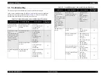
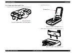
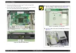
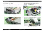
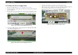
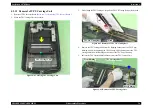
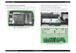
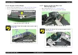
5. Disconnect the CR Motor Connector, Carriage FFC, and Power Supply Board
Connector connected to the Main Board.
6. Remove the four screws (C.B.S M3x5) and two Main Unit rear screws (C.P M3x4)
which secure the Main Board and then remove the Main Board.
Figure 4-14. Removal of Main Board
Carriage FFC
Power Supply Board Connector
C.B.S M3x5
(9±1 kgfcm)
CR Motor Connector
Main Board
Main Unit rear
C.P M3x4
(4±1 kgfcm)
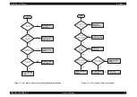
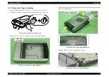
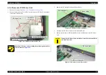
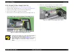
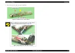
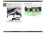
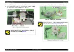
Pass the Carriage FFC through the Ferrite Core and adhere it
with a two-sided tape at the position shown in
.
Figure 4-15. Installation of Carriage FFC
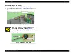
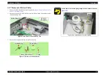
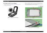
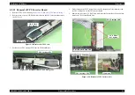
Pass the CR Motor Cable under the Shaft Holder as shown in
Figure 4-16. Routing CR Motor Cable
Ferrite Core
Position
CR Motor Cable
Shaft Holder
Содержание Perfection 4870 Photo
Страница 1: ...EPSON Perfection4870Photo Color Image Scanner Service Manual SESC03 008 ...
Страница 5: ...Revision Status Revision Date of Issue Description A December 10 2003 First release ...
Страница 8: ...C H A P T E R 1 PRODUCTDESCRIPTION ...
Страница 19: ...C H A P T E R 2 OPERATINGPRINCIPLES ...
Страница 29: ...C H A P T E R 3 TROUBLESHOOTING ...
Страница 37: ...C H A P T E R 4 DISASSEMBLY ASSEMBLY ...
Страница 63: ...C H A P T E R 5 ADJUSTMENT ...
Страница 65: ...C H A P T E R 6 MAINTENANCE ...
Страница 68: ...C H A P T E R 7 APPENDIX ...
Страница 71: ......
Страница 72: ......
Страница 73: ......
Страница 74: ......
Страница 75: ......
Страница 76: ......
Страница 77: ......
Страница 78: ......
Страница 79: ......
Страница 80: ......
Страница 81: ......