EPSON Perfection 3200 Photo
Revision A
Disassembly and Assembly
DISASSEMBLY AND ASSEMBLY
41
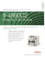
4.2.6 Main Circuit Board Removal
1.
Release the carriage lock. (See Section 4.2.1.)
2.
Remove the document cover. (See Section 4.2.2.)
3.
Remove the upper cover. (See Section 4.2.3.)
4.
Gently slide the carriage unit forward so that the main circuit board shield
plate is visible. (See Figure 4-17)
5.
Remove the two screws (CBS, M3x5) and disengage the three hooks, and
then remove the main circuit board shield plate. (See Figure 4-17)
6.
Disconnect the CR motor connector (CN7), carriage FFC connector (CN6)
and power supply circuit board connector (CN8) from the main circuit
board. (See Figure 4-18)
7.
Remove the four screws (CBS, M3x5) from the main circuit board and the
two screws (CP, M3x5) at the back of the scanner, and then remove the
main circuit board. (See Figure 4-18 and Figure 4-19)
Figure 4-17. Main Circuit Board Removal (1)
Figure 4-18. Main Circuit Board Removal (2)
Figure 4-19. Main Circuit Board Removal (3)
CBS Screws (3x5)
Tightening Torque : 8-10kgfcm
Main Circuit Board
Shield Plate
Hooks
Main Circuit Board
CBS Screws (3x5)
Tightening Torque : 6-8kgfcm
Carriage FFC
Connector
Power Supply Circuit
Board Connector
CR Motor
Connector
CP Screws (3x5)
Tightening Torque : 3-5kgfcm
Содержание Perfection 3200 Photo
Страница 1: ...EPSON Perfection3200Photo Color Image Scanner SESC02 003 SERVICE MANUAL ...
Страница 5: ...Revision Status Revision Issued Date Description A November 18 2002 First Release ...
Страница 8: ...C H A P T E R 1 PRODUCT DESCRIPTION ...
Страница 21: ...C H A P T E R 2 OPERATINGPRINCIPLES ...
Страница 29: ...C H A P T E R 3 TROUBLESHOOTING ...
Страница 36: ...C H A P T E R 4 DISASSEMBLYANDASSEMBLY ...
Страница 58: ...C H A P T E R 5 ADJUSTMENT ...
Страница 61: ...C H A P T E R 6 MAINTENANCE ...
Страница 64: ...C H A P T E R 7 APPENDIX ...
Страница 70: ......
Страница 71: ......
Страница 72: ......