background image


 Subassemblies

Removing the Speaker

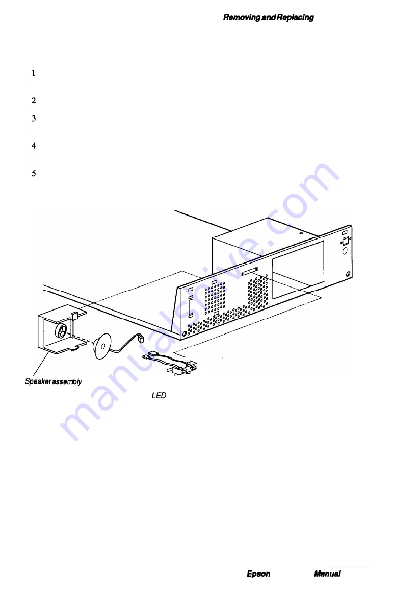
Follow these steps to remove the speaker:

Remove the cover (see page 3-2) and any option cards that may be in the way (see
page 3-5).

Disconnect the speaker cable from CN3 on the system board

From the front of the chassis lift up on the lower speaker unit tab to release it from the
lower chassis mounting hole (see Figure 3-15).

From the backside of the front chassis, pull the bottom of the speaker unit up and
away from the front of the chassis.

From the backside of the speaker unit the speaker can be removed by pushing it out of
its holder.


assembly

Figure 3-15 Speaker and LED Assemblies

Replacing the Speaker

Follow these steps to replace the speaker:

1

From the backside of the front chassis, insert the upper tab of the speaker unit into the
upper mounting hole and lower the bottom tab of the speaker unit down and into the
lower mounting hole in the front of the chassis (see Figure 3-15).

2

Connect the speaker cable to CN3 on the system board.

3

Replace any option cards removed and the cover.

 NX Service 

3-19

Содержание NX

Страница 1: ...EPSON NX Service Manual Printed on Recycled Paper ...

Страница 2: ...otherwise without the written permission of Epson America Inc No patent liability is assumed with respect to use of the information contained herein Nor is any liability assumed for damages resulting from the use of the information contained herein Trademark Information EPSON is a registered trademark of Seiko Epson Corporation Other product names used in this manual are for identification purpose...

Страница 3: ...ssion helpful How to Identify and Resolve Radio TV Interference Problems This booklet is available from the U S Government Printing Office Washington D C 20402 Stock No 044 000 00345 4 You can determine whether your computer is causing interference by turning it off If the interference stops it was probably caused by the computer or its peripheral devices To further isolate the problem disconnect ...

Страница 4: ...ion radioélectriques Canadiennes Le présent appareil numérique n émet pas de bruits radioélectriques dépassant les limites applicables aux appareils numériques de la classe B prescrites dans le règlement sur le brouillage radioélectrique édicté par le Ministère des Communications du Canada Other Agency Approvals Application for approval of this equipment has been made to the following agencies Uni...

Страница 5: ... assembly of the computer to its replaceable components Appendix A Reference Materials provides supplemental information that you may need when servicing the computer Appendix B System Utilities provides a summary of the SETUP program the System Diagnostics and other utilities on the Reference diskette Appendix C Schematics provides a series of system schematics A detailed Contents is provided at ...

Страница 6: ...ion l 6 Environmental Specifications l 7 Subassembly Descriptions l 8 Case l 9 SystemBoard 1 9 Connectors and Jumpers Connectors Jumpers Power Supply Memory Standard Memory BIOS ROM CMOS RAM Video DRAM Memory Expansion Mass Storage Diskette Drive and Tape Drive Options Hard Disk Drive Options Keyboard l 11 l 11 1 12 1 13 1 15 1 16 1 16 1 16 1 16 1 17 1 18 1 18 1 18 l 22 Epson NX Service Manual 1 i...

Страница 7: ...ntal Specifications l 7 Table l 6 Case Specifications l 9 Table l 7 System Board Component Functions l 9 Table l 8 System Board Connectors 1 12 Table l 9 System Board Jumper Settings Jl J4 1 12 Table l 10 System Board Jumper Settings J5 J8 1 12 Table l 11 System Board Jumper Settings J9 J15 1 12 Table 1 12 Power Supply Specifications 1 14 Table 1 13 Memory Configuration l 17 Table 1 14 Diskette an...

Страница 8: ...s standard with a 3 inch 1 44MB diskette drive There are four configurations giving you a choice of no hard disk drive a 170MB IDE a 240MB IDE or a 525MB SCSI hard disk drive Systems with hard drives come with the NeXTSTEP TM operating system preinstalled A 16 bit Ethernet adapter card also is installed Figure l l shows the main system unit and components that are packaged with the product monitor...

Страница 9: ...of on board memory in the 525MB HDD configuration expandable with SIMMs to 128MB 2MB of on hoard video DRAM Texas Instruments RAMDAC A 16 bit Ethernet adapter either an Intel EtherExpress TM 16C or an SMC EtherCard PLUS Elite16 Combo Selectable shadow RAM for system BIOS and video BIOS Two RS 232C serial ports and a Centronics standard bidirectional parallel port PS 2compatible mouse and keyboard ...

Страница 10: ...cription Front Panel Figure l 2 shows the features on the front panel of the system Table l 2 describes the front panel features Figure 1 2 Front View Table 1 2 Front Panel Features I Epson NX Service Manual 1 3 ...

Страница 11: ...System Overview Rear Panel Figure l 3 shows the features on the rear panel of the system Table 1 3 describes the rear panel features Figure 1 3 Rear View l 4 Epson NX service Manual ...

Страница 12: ...e 36 bit 70 ns SIMM option kits cl VGA Super VGA and multi frequency color monitors cl Epson 25OMB tape backup drive a Media Vision Spectrum TM 16 multimedia sound card cl Labtec CSS 550 speaker option kit Upgrades Figure l 4 shows the possible CPU upgrade paths for the standard system configurations You can find instructions for removing and replacing CPUs in Chapter 3 Figure 1 4 CPU Upgrade Path...

Страница 13: ...ssions and Safety Agency Information The Epson NX in a typical configuration meets or exceeds the requirements of the emissions and safety agencies listed in Table l 4 Table 1 4 Emissions and Safety Agency Data l 6 Epson NX Service Manual ...

Страница 14: ...System Description Environmental Specifications Table l 5 lists the environmental specifications for the Epson NX Table l 5 Environmental Specifications Epson NX Service Manual 1 7 ...

Страница 15: ...ns and specifications for the following subassemblies 0 Case cl System board along with connectors and jumpers 0 Power supply cl Memory ci Disk drives 0 Keyboard Figure l 5 shows the major subassemblies of the computer Figure 1 5 System Level Assemblies 1 8 Epson NX Service Manual ...

Страница 16: ...5 and described in Table 1 6 below Table 1 6 Case Specifications System Board Figure l 6 shows the major components on the main system board The functions of these components are described in Table l 7 Table 1 7 System Board Component Functions Epson NX Service Manual 1 9 ...

Страница 17: ...Subassembly Descriptions Figure l 6 System Board Components 1 10 Epson NX Service Manual ...

Страница 18: ... the main system board The location of each connector and jumper block is shown in Figure l 6 Connectors Table l 8 lists the connectors on the main system board You can find a description of all connector pin assignments in Appendix A Table 13 System Board Connectors Epson NX Service Manual 1 71 ...

Страница 19: ...placed on a set of pins The jumper connects either pin A and the middle pin or pin B and the middle pin The jumper settings are defined in Table 1 9 Table l 10 and Table l 11 Table 1 9 System Board Jumper Settings 51 54 Table l 10 System Board Jumper Settings JS J8 Table l 11 System Board Jumper Settings J9 515 1 12 Epson NX Service Manual ...

Страница 20: ...ents for the power supply are met by the standard configuration of the main circuit board To prevent damage from excessive temperature inside the computer the power supply includes sensors and a detection circuit that shuts down the power supply when an excessive operating temperature is detected To restart the computer you must identify and correct the problem that caused the system to overheat s...

Страница 21: ...Subassembly Descriptions Table 1 12 Power Supply Specifications Figure l 8 shows the power supply cable layout and connectors 1 14 Epson NX Service Manual ...

Страница 22: ...sists of eight high performance 512KB 70 ns chips The system supports 1 4 16 or 64MB when available 70 ns SIMMs two SIMMs may be installed for a maximum of 128MB Memory is controlled by a custom ASIC designed by Epson that permits burst cycles from standard DRAM The system memory has the following features 0 Standard memory includes cache and shadow RAM 0 ROM BIOS and CMOS RAM 0 Video DRAM 0 Zero ...

Страница 23: ...e BIOS supports all applications that run on PC XT AT systems and supports all ISA option cards The system board contains a 128KB EPROM in Ul for the system and video BIOS plus the code for the SETUP utility The 64KB EPROM in U113 contains the Nanguage text messages for SETUP The current BIOS version is shown during system start up Installing a new version of the BIOS requires replacement of the E...

Страница 24: ...s Table 1 13 shows the possible memory expansion configurations Table 1 13 Memory Configuration SIMM positions can be reversed to achieve same total memory l 20MB of RAM is standard for 170MB and 240MB HDD configurations 36MB of RAM is standard for the 525MB HDD configuration The standard 4 MB of memory is not accessible when both SIMM sockets are populated with 64MB SIMMs Epson NX service Manual ...

Страница 25: ... two diskette drives of any of the following 3 inch 72OKB or 1 44MB and 5 inch 360KB or 1 2MB drives The controller can also support one tape drive The standard diskette drive is a Mitsumi D 359T3 drive Optional diskette drives can be selected from Table 1 14 Table 1 14 Diskette and Tape Drive Options Hard Disk Drive Options There are three optional hard disk drive configurations available from th...

Страница 26: ...System Description Specifications for the Conner CP30174E HDD Table 1 16 Specifications for the Quantum LPS525S HDD Table 1 18 Quantum LPS525S 52SMB SCSI HDD Specifications Epson NX Service Manual 1 19 ...

Страница 27: ...HDD Master DS jumpered Slave not jumpered or if drive is configured for cab e selection using the CS jumper the drive is a master drive if pin 28 is grounded and a slave if pin 28 is not grounded Quantum LPS525S 525MB SCSI HDD See Table 1 19 for jumper settings Figure l 10 Jumper Placement for HDDs 1 20 Epson NX Service Manual ...

Страница 28: ...System Description Table 1 19 Quantum LPS525S Jumper Settings bus to be used when drive is Factory default jumper setting Epson NX Service Manual 1 21 ...

Страница 29: ...led cable Adjustable legs allow you to use the keyboard at two different heights Figure l 11 shows the l0l key keyboard A 102 key model is also available Table l 20 provides the specifications for the l0l key keyboard Figure l 11 l0l Key Enhanced Keyboard Table l 20 Keyboard Specifications 1 22 Epson NX Service Manual ...

Страница 30: ...12 Hard Disk Problems 2 13 Newly installed Drive Problems 2 13 Hard Disk Boot Failure 2 14 System Software Problems 2 14 Parallel Printer Problems 2 15 Serial Port Problems 2 16 Option Card Problems 2 17 Memory Module Problems 2 18 Mouse Problems 2 19 Troubleshooting with the NeXTSTEP Operating System 2 20 Figures Figure 2 l Power or Lock up Problems 2 7 Figure 2 2 Keyboard Problems 2 9 Figure 2 3...

Страница 31: ...Tables Table 2 l Recommended Service Tools 2 l Table 2 2 Authorized Replacement Modules 2 2 Table 2 3 Power on Diagnostic Error Messages 2 3 Table 2 4 Error Beep Codes 2 6 2 ii Epson NX Service Manual ...

Страница 32: ... The diagnostics are broken down into three sections 0 Power on diagnostics and boot errors cl Error tone codes cl General system problems Recommended Service Tools The recommended service tools are listed in Table 2 1 All tools are commercially available Table 2 1 Recommended Service Tools Epson NX Service Manual 2 l ...

Страница 33: ...r to indicate when you should replace that module and test the system again Table 2 2 Authorized Replacement Modules Rep h aut lacement of these components is performed only by orized service centers outside the U S Servicers In the U S should replace the system board when there is a malfunction of any of the components marked with an asterisk 2 2 Epson NX Service Manual ...

Страница 34: ...cribed below In some instances the computer may also sound a beep This happens when the error occurs before the computer initializes the video display If the error is serious the computer cancels further checking and halts system initialization The error message remains on the screen and the computer locks up Table 2 3 provides a list of the error messages that may appear The solutions that are pr...

Страница 35: ...Power On Diagnostics and Boot Errors 2 4 Epson NX Service Manual ...

Страница 36: ...onents is performed only by authorized service centers outside the U S Servicers in the U S should replace the system board when there is a malfunction of any of the components marked with an asterisk Epson NX Service Manual 2 5 ...

Страница 37: ...g beep and two short beeps If there are no errors the system beeps once before it loads the operating system Table 2 4 lists the error beep codes Table 2 4 Error Beep Codes Replacement of these components is performed on centers outside the U S by authorized service Servicers in the U S should replace the system board when there is a malfunction of any of the components marked with an asterisk 2 6...

Страница 38: ...performed the suggested solution Only go on to the next step when the suggested solution fails For certain problems a hardware test is available as one of the options of the System Diagnostics You can find the System Diagnostics program on the Reference diskette user instructions are in the User s Guide and a summary can be found in Appendix B of this manual Power or Lock up Problems If there is a...

Страница 39: ...gh temperature they shut off all the DC outputs in the power supply and the computer stops operating This does not damage the power supply but you must remove the cause of the high temperature before the system can be used again After you eliminate the problem causing the overheating allow the computer to cool down for at least five minutes at a room temperature of about 25 C 78 F This resets the ...

Страница 40: ...yboard cable is securely connected to the keyboard port and not the mouse port 2 Check the keyboard cable connector for any bent or missing pins If necessary repair the connector or replace the cable 3 Replace the keyboard unit The internal circuit board may be faulty 4 Replace the keyboard controller The controller may be faulty 5 Check the continuity of fuse Fl 1A 125V on the system board and re...

Страница 41: ...keyboard s upper and lower cases are properly aligned 2 Remove the sticking keys and clean all internal parts 3 Remove the keys and replace any broken parts Video Problems If there is a problem with the computer s video system see the suggestions below Figure 2 3 Video Problems 2 10 Epson NX Service Manual ...

Страница 42: ...dapter is monochrome make sure that jumper Jll is in position B Replace the monitor Replace the system board The video controller may be faulty Authorized service centers outside the U S can replace the video controller chip Incorrect Images If the screen displays incorrect or blurred images follow these suggestions 1 Make sure the monitor cables are securely connected to the monitor the computer ...

Страница 43: ...ller is enabled 2 Remove the computer cover and make sure the diskette drive interface and power connectors are completely inserted Replace the cover 3 Test the drive by running the diskette drive diagnostics test If the test indicates an error replace the diskette drive 4 Replace the system board The FDD controller in the 82C711 gate array may be faulty Authorized service centers outside the U S ...

Страница 44: ...ey are set correctly 3 Lf you installed a non Epson hard disk drive verify that it has a DOS partition The hard disk drives Epson provides with the Epson NX have a DOS partition as well as a partition for NeXTSTEP software You can check for a DOS partition by booting with a DOS system diskette and running the FDISK program If FDISK reports that no partition exists then it means that DOS has not be...

Страница 45: ...he hard disk and reinstall the operating system on it See Hard Disk Problems on page 2 13 5 If the hard disk is not an IDE type perform a low level format on the HDD with the Hard Disk Format program on the Reference diskette See the User s Guide for instructions Reformat the hard disk and reinstall the operating system on it System Software Problems If there is a problem using the built in system...

Страница 46: ...er s correct DIP switch or control panel settings Try a different cable Also try a different printer if one is available If there is more than one parallel port check the primary and secondary port settings in the SETUP program to make sure they are correct Run the parallel port diagnostics test Replace the system board Connector CN5 or the parallel port controller in the F82C711 gate array may be...

Страница 47: ...nd number of stop bits of the device and serial port must match Try a different cable Also make sure you are using a null modem cable if the device is a serial printer Check the primary and secondary port settings in the SETUP program to make sure they are correct Run the Serial port Diagnostics test Replace the system board Connectors CN4 and CN8 or the serial port controller in the F82C711 gate ...

Страница 48: ...the proper cable to connect the device to the option card connector Switch the system to low speed If you still have trouble with the option card and the system is using a memory manager program such as QEMM 386 TM or 386MAX TM try removing the program from memory and rebooting your computer Some cards may use a part of the memory address space that conflicts with the addresses assigned to Video S...

Страница 49: ...nserted all the way into their sockets Remove the cover and check the installation 2 Verify the speed of the SIMMs Install only 70 ns or faster 36 bit gold plated fast page mode SIMMs 3 Run the SETUP program to check the memory configuration 4 Run the memory diagnostics test 5 Replace the SIMMs one at a time 6 Replace the system board The SIMM connectors or memory controller in the EP6075 gate arr...

Страница 50: ... whether the mouse driver program is loaded into the computer s memory correctly Check the mouse cable connector for any bent or missing pins Check that the built in mouse port jumper J9 is in position A Replace the mouse It may be faulty For servicers outside the U S replace the keyboard mouse controller The controller may be faulty Check the continuity of fuse Fl 1 A 125V on the system board Rep...

Страница 51: ...nd power off the system Hold down the right Alt key press Num Lock and then press h to halt the system 2 If there is an abnormal system shut down the NeXTSTEP operating system runs an extensive check of the hard disk drive to investigate the problem The screen displays the message Checking disks for several minutes After successfully running the system check NeXTSTEP cleans the file system state i...

Страница 52: ...2 InstalIing Another Processor 3 13 Removing a Drive From the Horizontal Position 3 14 Installing a Drive In the Horizontal Position 3 15 Removing a Hard Disk Drive From the Vertical Position 3 17 Installing a Hard Disk Drive In the Vertical Position 3 18 Removing the Power Supply 3 19 Reinstalling the Power Supply 3 20 Removing the Speaker 3 21 Replacing the Speaker 3 21 Removing the LEDs 3 22 Re...

Страница 53: ...moving Installing the Processor 3 13 Figure 3 9 Removing Installing a Horizontal Drive 3 14 Figure 3 10 Removing Installing Drive Panels 3 15 Figure 3 11 Attaching Drive Cables 3 16 Figure 3 12 Removing Installing a Vertical HDD 3 17 Figure 3 13 Power Supply Assembly 3 19 Figure 3 14 Power Supply Power Cables 3 20 Figure 3 15 Speaker and LED Assemblies 3 21 Figure 3 16 BIOS Chips Installation 3 23...

Страница 54: ...tic sensitive CMOS devices To prevent damage from static electricity always discharge body static by touching a grounded surface before opening the computer s case Always wear a grounded wrist strap when handling any circuit boards or cables inside the computer Do not touch any of the circuit board components or connector pins with your hands including the gold edge connectors as damage from stati...

Страница 55: ... computer s cover 1 Turn off the computer and then any peripheral devices including the monitor and printer 2 Disconnect the computer s power cable from the electrical outlet and from the back panel if you plan to remove a major component Also disconnect any cables that are connected to the computer including the keyboard cable 3 If the monitor is on top of the computer lift it off and set it to o...

Страница 56: ...el is facing you 7 Grasp the sides of the cover and pull it straight toward you until it stops just before it reaches the front of the computer Then lift it off at an angle as shown in Figure 3 2 Figure 3 2 Removing the Cover 8 Set the cover aside on a flat surface Epson NX Service Manual 3 3 ...

Страница 57: ...own in Figure 3 3 Chassis Cover Figure 3 3 Replacing the Cover 2 Lower the cover and slide it straight back over the computer until it stops against the rear panel 3 Replace the three cover retaining screws as shown in Figure 3 1 4 Reconnect the computer to the monitor printer keyboard mouse and any other peripheral devices Then reconnect the power cable to the back of the computer and to an elect...

Страница 58: ...he computer as shown in Figure 3 4 Then pull the card straight out from the riser board Figure 3 4 Removing Installing the Option Card 3 Set the option card aside with the component side facing up Note After removing an option card check to see if any jumper settings on the main system board need to be changed For example if you remove a mouse interface card the setting of jumper J12 needs to be c...

Страница 59: ...crew to secure the option card to the computer Store the slot cover in a safe place in case the option card is later removed Figure 3 5 Removing Replacing the Option Slot Cover Replacing the Option Slot Cover Follow these steps to replace the option slot cover 1 Remove the cover as described on page 3 2 2 To replace the option slot cover insert the cover as shown above in Figure 3 5 and secure it ...

Страница 60: ...ed If installing a video card the settings of jumpers Jl0 or Jl 1 may need to change See page l l2 for more information on jumper settings Follow these steps to install an option card that has been removed or to add a new option card in the computer 1 Remove the computer s cover as described on page 3 2 2 Remove the option slot cover as described on page 3 6 3 Unpack the option card and adjust any...

Страница 61: ...n in Figure 3 6 Then remove the bracket Figure 3 6 Removing the Option Card Riser Board 4 Using both hands pull the riser board straight up and out of its socket CN14 5 Set the board aside Replacing the Option Card Riser Board Follow these steps to reinstall the option card riser board inside the computer 1 Position the board above its slot CN14 as shown in Figure 3 6 and then firmly push it strai...

Страница 62: ...ch end Be careful not to pull the tabs too far or they may bend Metal Tab Figure 3 7 Removing SIMMs As you pull away the tabs the SIMM falls to the side of its socket as shown in Figure 3 7 When the SIMM is at an angle carefully remove the SIMM and store it in an anti static bag Repeat steps 3 and 4 for removing additional SIMMs Replace any option cards removed see page 3 7 Replace the computer s ...

Страница 63: ...so its component side is toward the left side of the computer then insert it in the socket at a slight angle See Figure 3 7 5 Gently press down on the SIMM and at the same time press the top corners forward until the SIMM is vertical and clicks into place between the metal clips and the retaining posts Make sure the SIMM is fully inserted into the socket and that the retaining post pins fit into t...

Страница 64: ...egs of the CPU in the socket 3 Gently lift the CPU out of the socket and place it in an anti static bag for protection Figure 3 8 Removing Installing the Processor 4 Locate the orientation dot in one corner of the new CPU and turn the CPU so that the dot is in the position shown in Figure 3 8 Be sure the dot is aligned with the corner that has a 1 printed on the system board Caution If you insert ...

Страница 65: ... chassis Then gently pull the drive out from the front of the bay as shown in Figure 3 9 Figure 3 9 Removing Installing a Horizontal Drive 4 Keep the screws so that you can use them to install a drive later 5 When removing the lower drive replace the lower drive bay cover on the chassis and on the front panel as shown in Figure 3 10 6 If one of two hard disk drives is removed the jumpers on the re...

Страница 66: ...panel See Figure 3 10 Store the cover in a safe place Figure 3 10 Removing Installing Drive Panels 3 Attach the two mounting rails to the appropriate holes on the sides of the drive with four screws as shown below The mounting rails are included with the system and if removed from a drive they should be stored in a safe place for future use 4 If you are installing a 5 inch diskette drive turn it s...

Страница 67: ...ctor CN6 Use the middle connector to connect the second drive if one end is already connected to a hard drive or leave the middle connector free and use the end connector if no other HDD drive is present 7 Ensure that the connector is aligned properly and fits properly onto the drive interface See Figure 3 11 Drive cable Figure 3 11 Attaching Drive Cables 8 Locate one of the power supply cable con...

Страница 68: ...rd drive and its mounting bracket the mounting bracket has tabs inserted in slots on the bottom of the system chassis 4 Remove the four screws located on the back of the hard drive mounting bracket to remove the hard drive Keep the screws so that you can use them to install a drive later Figure 3 12 Removing Installing a Vertical HDD 5 Replace the hard drive mounting bracket onto the drive bay and...

Страница 69: ...ated on the bottom of the system chassis and gently lift it out 4 Secure the hard disk drive onto the mounting bracket with the four screws located as shown in Figure 3 12 5 Align the tabs of the mounting bracket with the slots in the bottom of the system chassis then slide the bracket toward the front of the computer Secure the bracket with the screw removed in step 2 above 6 Plug the drive and p...

Страница 70: ...the power supply see Figure 3 13 5 Remove any option cards and the option card riser board see page 3 8 6 Disconnect the power cable connectors PS1 and PS2 from the system board CN13 7 Remove the four screws securing the power supply to the rear panel 8 Remove the two screws securing the power supply to the base of the system chassis and then the two screws attaching the power supply chassis brack...

Страница 71: ...o the system board connector CN13 see Figure 3 14 PS2 PSl Figure 3 14 Power Supply Power Cables 7 Reinstall the option card riser board and any option cards see page 3 8 8 Push the power switch through the front panel and secure it in place with two screws 9 Connect the grounding wire to the front of the chassis 10 Connect one power cable connectors PA through PD to each drive in the system see Fi...

Страница 72: ...r unit up and away from the front of the chassis From the backside of the speaker unit the speaker can be removed by pushing it out of its holder Speaker assembly LED assembly Figure 3 15 Speaker and LED Assemblies Replacing the Speaker Follow these steps to replace the speaker 1 From the backside of the front chassis insert the upper tab of the speaker unit into the upper mounting hole and lower ...

Страница 73: ...f the chassis until the left tab of the LED unit clears its mounting hole Replacing the LEDs Follow these steps to replace the LED unit 1 Ensure the LED wires are inserted through the LED access hole in the front of the chassis Insert the left tab of the LED unit into its mounting bracket then swing the right locking tab into its mounting hole Ensure the LED wires are inserted through the LED acce...

Страница 74: ...tion Replacing the BIOS EPROMs Follow these steps to install the BIOS EPROM chips in sockets Ul and U113 1 Remove the cover see page 3 2 and any option cards that may be in the way see page 3 5 2 Gently insert the System VGA EPROM into socket Ul Align the half circle notch of the chip with the notch of the socket to assure proper orientation see Figure 3 16 Figure 3 16 BIOS Chips Installation 3 Ge...

Страница 75: ... CN11 and CN16 any VGA feature connector at CN17 and cables connected to the serial parallel mouse video and keyboard ports 3 Remove the six screws that secure the system board to the main chassis see Figure 3 17 Figure 3 17 Removing Replacing the System Board 4 Pull the system board forward then tilt it up Then pull the system board slightly toward you and lift it up and out of the chassis Place ...

Страница 76: ...ining screws see Figure 3 17 5 Reinstall the option card riser board see page 3 8 and replace any option cards see page 3 7 6 Reconnect all cables and replace the cover Removing the Front Bezel Follow these steps to remove the front bezel 1 Remove the cover see page 3 2 2 Remove the two retaining screws located on the back side of the bezel as shown in Figure 3 18 Figure 3 18 Removing Replacing th...

Страница 77: ...he cover upside down on a smooth flat surface and gently push the front panel locking tabs into the tab slots located in the front end of the cover 2 Secure the front panel to the cover with the two retaining screws see Figure 3 18 3 Replace the cover see page 3 4 3 24 Epson NX Service Manual ...

Страница 78: ...E Hard Disk Drive Data Connector A 10 Diskette Drive Data Connector A 11 Keyboard and Mouse Connectors A 12 Battery Connector A 13 ResetConnector A 13 Power Supply Connectors A 14 Option Card Riser Board Connector A 14 HDD Access LED Connector A 16 Power SPEED LED Connector A 16 VGA Feature Connector A 17 Option Slot Connectors A 18 Drive Power Connectors A 19 Intel Ether Exprcss 16C A 19 SMC Ethe...

Страница 79: ...A 7 Table A 8 Table A 9 Table A 10 Table A 11 Table A 12 Table A 13 Table A 14 Table A 15 Table A 16 Table A 17 Table A 18 Table A 19 Table A 20 Table A 21 Auxiliary Fan Connector Pin Assignments A 7 VGA Port Connector Pm Assignments A 7 Speaker Connector Pin Assignments A 8 Serial Port Connector Pin Assignments A 8 Parallel Port Connector Pin Assignments A 9 IDE Hard Disk Drive Data Connector Pin...

Страница 80: ...Hard Disk Drive Types Epson NX Service Manual A l ...

Страница 81: ...Had Disk Drive Types A 2 Epson NX Service Manual ...

Страница 82: ...System l O Address Map Epson NX Service Manual A 3 ...

Страница 83: ...System I O Address Map A 4 Epson NX Service Manual ...

Страница 84: ...DMA Assignments Epson NX Service Manual A 5 ...

Страница 85: ...Hardware Interrupts A 6 Epson NX Service Manual ...

Страница 86: ...ctor that has no posts and is in place for future use Figure A l shows the connector and Table A l provides the pin assignments VGA Port Connector The VGA connector CN2 is a 15 pin D shell female receptacle accessible from the rear of the computer Figure A 2 shows the connector and Table A 2 provides the pin assignments Table A 2 VGA Port Connector Pin Assignments Epson NX Service Manual A 7 ...

Страница 87: ...stem board Figure A 3 shows the connector and Table A 3 provides the pin assignments Serial Port Connectors The serial ports CN4 and CN8 are 9 pin D shell male connectors accessible from the rear of the computer Figure A 4 shows the connector and Table A 4 provides the pin assignments Table A 4 Serial Port Connector Pin Assignments A 8 Epson NX Service Manual ...

Страница 88: ...nector The parallel port connectar CNS is a 25 pin D shell female connector accessible from the rear of the computer Figure A 5 shows the connector and Table A 5 provides the pin assignments Epson NX Service Manual A 9 ...

Страница 89: ...Connector The IDE hard disk drive data connector CN6 is a 40 pin header connector accessible from inside the computer and located on the system board Figure A 6 shows the connector and Table A 6 provides the pin assignments A 10 Epson NX Service Manual ...

Страница 90: ...nector The diskette drive data connector CN7 is a 34 pin header connector accessible from inside the computer and located on the system board Figure A 7 shows the connector and Table A 7 provides the pin assignments Epson NX Service Manual A 11 ...

Страница 91: ...nnectors are 6 pin mini DIN receptacles accessible from the rear of the computer Figure A 8 shows the connector and Table A 8 provides the pin assignments Note Although the keyboard and mouse connectors are physically identical they cannot be used interchangeably A 12 Epson NX Service Manual ...

Страница 92: ... A 9 shows the connector and Table A 9 provides the pin assignments Reset Connector The reset connector CN12 is a 2 pin connector that has no posts and is in place for future use Figure A 10 shows the connector and Table A 10 provides the pin assignments Figure A 10 Reset Connector Table A 10 Reset Connector Pin Assignments Epson NX Service Manual A 13 ...

Страница 93: ...he connector Table A 11 provides the pin assignments Figure A 11 Power Supply Connector Table A 11 Power Connector Pin Assignments Option Card Riser Board Connector The riser board connector CN14 is a 120 pin female recepticle that supplies power and interface lines to the four option slots on the riser board Figure A 12 shows the connector and Table A 12 provides the pin assignments A 14 Epson NX...

Страница 94: ...Reference Materials Table A 12 Option Card Riser Board Connector Pin Assignments Epson NX Service Manual A 15 ...

Страница 95: ...e connector and Table A 13 provides the pin assignments Power SPEED LED Connector The Power LED connector CN16 is a 3 pin male header connector accessible from inside the computer and located on the system board Figure A 13 shows the connector and Table A 14 provides the pin assignments Figure A 13 Power SPEED LED Connector Table A 14 Power SPEED LED Connector Pin Assignments A 16 Epson NX Service...

Страница 96: ...VGA Feature connector CN17 is a 26 pin header accessible from the inside of the computer Figure A 15 shows the connector and Table A 15 provides the pin assignments Figure A 15 VGA Feature Connector Epson NX service Manual A 17 ...

Страница 97: ...lot connectors on the riser board are 98 pin female receptacles Figure A 16 shows one of these connectors and Table A 16 provides the pin assignments Figure A 16 Option Slot Connector Table A 16 Option Slot Connector Pin Assignments A 16 Epson NX Service Manual ...

Страница 98: ...rovides the pin assignments Intel Ether Express 16C The Intel EtherExpress 16C is a 16 bit ISA compatible Ethernet adapter card that supports BNC coax thin Ethernet AUI DB 15S thick Ethernet and RJ45 10BaseT Ethernet The card is software configurable for I O address IRQ connector type and I O or memory mapped buffering A diagnostic utility is included Table A 18 Intel EtherExpress LED Indicators E...

Страница 99: ... address IRQ connector type and I O or memory mapped buffering A diagnostic utility is included By default this card uses I O address 280 IRQ3 and RAM base address D0000 You can move jumper W 1 shown in the figure above to SOFT to use the adapter setup program to select the I O address IRQ and RAM base address or move it to 300 10 CC000 to select I O address 300 IRQlO and RAM base address CC000 Ta...

Страница 100: ...Adaptec AHA 1504B Figure A 19 Adaptec Jumper Locations Table A 20 Adaptec Default Settings Epson NX Service Manual A 21 ...

Страница 101: ...Connector Pin Assignments Table A 21 Adaptec Jumper Settings A 22 Epson NX service Manual ...

Страница 102: ...Adaptec Jumper Settings Continued Epson NX Service Manual A 33 ...

Страница 103: ...List of Abbreviations List of Abbreviations A 24 Epson NX Service Manual ...

Страница 104: ...Reference Materials Epson NX Service Manual A 25 ...

Страница 105: ... B 10 Network Server and Password Status B 10 Setting the Network server mode B 10 Setting the Password security B 10 Setting the Password B 11 Installed Diskette Drive s B 11 Installed Hard Disk Drive s B 11 Hard Disk Drive Types B 11 Defining Your Own Drive Type B 12 Setting the Non cache Areas B 13 Setting the Cache Test and User Control Options B 14 Setting the High Vertical Refresh Rate B 14 ...

Страница 106: ...31 Changing the Processor Speed B 31 Preparing the Hard Disk for Moving B 31 Tables Table B l SETUP Keycommands B 3 Table B 2 Processor Speed Options B 6 Table B 3 I O Address Options B 10 Table B 4 Non cache Address Areas B 13 Table B 5 Vertical Refresh Rate Options B 14 Table B 6 System DiagnosticsTests B 21 Table B 7 System Diagnostic Error Messages B 22 Table B 8 ESPEED Command Options B 31 B ...

Страница 107: ...ive and hard disk drive controller operation Password and network server mode operation Type s of diskette and hard drive s installed Cache cache testing and non cacheable address operation for internal cache in the i486DX2 66 microprocessor High vertical refresh rate setup If someone has set a password you may need to move jumper J13 from the B position enabled to the A position disabled to acces...

Страница 108: ... the system ROM If this happens reset the computer to try again The SETUP Screens After pressing F2 or entering SETUP at the MS DOS prompt you see the first screen of SETUP information There are several screens of SETUP options A box in the lower left comer continuously displays the current date and time The help lines at the bottom of the screen list some of the keys you can press to perform vari...

Страница 109: ...ons When you reach an option you want to change press Enter to edit the option Then press the or keys on the numeric key pad or the keyboard or shift to toggle between choices When the setting is correct press or to go to the next option Table B l lists the keys you can use to perform all SETUP operations Table B l SETUP Key commands Epson NX Service Manual B 3 ...

Страница 110: ...s for the current month such as 09 for September The cursor moves to date dd field Type the current two digit date and the cursor moves to the year yyyy field Type four digits for the year for instance 1999 and press Enter If you make a mistake press Backspace to erase the characters before you press Enter If an invalid date such as month 13 is entered the date prompt will flash on the month mm fi...

Страница 111: ...k For example 5 p m would be hour 17 Then press Enter If you make a mistake press Backspace to erase the characters before you press Enter If an invalid time such as hour 25 is entered the time prompt will flash on the hour hh field again Repeat step 5 again and enter a valid date The time prompt disappears and the date and time set is displayed on the screen Epson NX Service Manual B 5 ...

Страница 112: ...te at one of three different speeds high low and automatic speed Note When the processor is running at high speed the SPEED light on the front panel is green when it runs at low speed the SPEED light is amber The automatic setting causes the system to run at low speed when a diskette drive is accessed and at the high speed at all other times The Software sgeed change option disables the keyboard s...

Страница 113: ... to use AT compatible software For PS 2 compatible software change the On board video BIOS located at address to E000h To exclude certain portions of RAM up to 12 16KB address areas from being used for Shadow RAM areas press the End key to go to the bottom of the options menu Then enable or disable shadow RAM in these address ranges cl cl cl cl P 0 cl cl cl cl cl cl C000h C3FFFh C400h C7FFFh CS00h...

Страница 114: ...e changed anytime The Keyboard delay default setting is 250 ms or second The options are 0 250 500 750 or 1000 milliseconds ms The Keyboard speed default setting is 020 kps keys per second The options are any speed between 002 and 031 kps The Num Lock status after boot default setting is ON The option is OFF Installed Equipment Setup displays information about the following equipment except for ma...

Страница 115: ...d as COMl or COM2 change the setting to Disabled This may he necessary if a FAX modem hoard is installed Setting the Speaker The speaker s default setting is Enabled which allows the speaker to beep during certain operations To turn the speaker off change the setting to Disabled Setting the Internal Diskette Drive Controller The internal diskette drive controller s default setting is Enabled which...

Страница 116: ...options Network Server and Password Status The password status options let you define the password for the following cl Network server mode Cl Password security a Password Setting the Network sewer mode The network server s default setting is Not installed To install the network server security mode change the setting to I n s t a l l e d Setting the Password security The default setting is Not in...

Страница 117: ...low these guidelines to choose the correct setting for each drive cl If the system does not have a hard drive select Not installed for drives 1 and 2 If one hard disk drive is installed select Not installed for drive 2 cl If a Conner 170MB hard disk drive is installed as drive 1 select type 26 0 If a Quantum 240MB hard disk drive is installed as drive 1 select type 34 ci If a Quantum 525MB SCSI dr...

Страница 118: ...e top of the keyboard or the numeric keypad to enter the appropriate values for these parameters Enter number of cylindera on disk Enter number of cylinder heads Enter number of sectors per track The total amount of storage capacity on the disk is calculated by SETUP automatically based on the other values entered Press Enter after typing each number If you enter an invalid number the computer bee...

Страница 119: ...ea If you set any user defined non cache areas SETUP automatically sets the high address at least 4KB higher than the corresponding low address To change the setting of a system defined non cache area select the address area and press or to choose enabled or disabled To disable caching in a user defined non cache area set the beginning address of the range in the low address option then set the en...

Страница 120: ... Settings After you have made your selections for SETUP press Esc to exit You see the following prompt Save and Exit No Save and Exit Return to Setup To save the settings in the CMOS RAM highlight Save and exit and press Enter To exit SETUP without saving your changes press to highlight No Save and Exit then press Enter To remain in SETUP select Return to Setup and press Enter the exit menu disapp...

Страница 121: ... y o u m a y s e e d u r i n g t e s t i n g You can test the following devices using System diagnostics System board cl Numeric coprocessor cl System memory 0 Diskette drive s Li Hard disk drive s P Serial ports Ll Parallel port s cl Video adapter cl Dot matrix printer s Note When performing diskette and hard disk diagnostics the Write Read function checks may destroy data on the disk Be sure to ...

Страница 122: ... program 2 At the A prompt type DIAG and press Enter 3 You see a menu bar at the top of the screen with Items Detected highlighted Press Enter 4 You see a list of all the testable devices the computer detects in your system If the list is correct go to page B 19 5 If the list is not correct press to select Quit and press Enter Run the SETUP program to make sure any missing devices ate configured p...

Страница 123: ...1 Press to select Delete Tests You see the Delete menu as shown below 2 Press or to highlight the device you want to delete and press Enter The device is removed from the Delete menu You can delete as many devices as you want 3 When you are finished deleting devices press to select Execute see Running Tests on page B 19 Epson NX Service Manual B 17 ...

Страница 124: ...d Tests You see the following Add menu 2 Press or to highlight the device you want to add and press Enter The device is removed from the Add menu and added to the Items Detected list You can add as many devices as you want 3 When you are finished adding devices press to select Execute Then see the next section B 18 Epson NX Service Manual ...

Страница 125: ...System Utilities Running Tests Follow these steps to run a test from the Execute menu 1 Press or to select Execute You see the following Execute menu Epson NX Service Manual B 19 ...

Страница 126: ...an select another test or exit the menu To exit system diagnostics press to select Quit and press Enter You return to the operating system command prompt Resuming From an Error If an error prevents a test from running you see a Runtime Error information box Follow the instructions on the screen to solve the problem If an error occurs during a test the test stops and an error message appears Follow...

Страница 127: ...le below lists all the system diagnostics tests you can run on your system Table B 6 System Diagnostics Tests The Write Read check destroys data on the disk disk or insert a blank diskette Be sure to back up data on a hard Epson NX Service Manual B 21 ...

Страница 128: ...ing System Diagnostics Error Messages The following table lists all the error messages that may appear during system diagnostics testing Table B 7 System Diagnostics Error Messages B 22 Epson NX Service Manual ...

Страница 129: ...System Utilities Epson NX Service Manual B 23 ...

Страница 130: ...itions and logical formatting defined on the disk by the operating system After you physically format a new or used hard disk you need to logically format the disk again using the operating system Starting the Program Follow these steps to start the hard disk formatting program 1 Insert the Reference diskette in drive A and start the system 2 Type HDFMTALL and press Enter You see the Hard Disk For...

Страница 131: ... the non destructive surface analysis back up your hard disk to diskettes 3 Run the Destructive surface analysis option to update the defective track table 4 Run the Format option to format the disk Selecting an Option When you use this program you often need to select an option from a menu There am two ways to do this cl Use the arrow keys to highlight the optionand press Enter cl Type the number...

Страница 132: ...ood tracks 4884 2 Next you see the following prompt Accept recomnended skewed sectors in format 1 Y N For a hard disk drive installed by Epson it is best to accept the recommended skewed sector also called the interleave factor of 1 since this setting allows your drive to perform more efficiently For other hard disk drives you may need to change this value if the documentation that came with the d...

Страница 133: ... this prompt Enter cylinder number 1 nnnn 2 Type the number of the cylinder containing the bad track and press Enter You see this prompt Enter head number 0 nn 3 Type the head number for the bad track and press Enter To cancel the operation press Enter without typing a value When you complete a valid entry it appears in the table and you can add the next bad track if necessary If you make a mistak...

Страница 134: ...el DOUBLE CHECK THAT YOU HAVE BACKUP DISKETTE COPIES OF ALL YOUR FILES Do you want to exit and check your file copies Y N Select Y to cancel formatting or N to continue If you continue with formatting you see Format started Head nnn Cylinder nnnnn You see the head and cylinder numbers decrease as the program progresses When formatting is complete the program flags any bad tracks and you see a seri...

Страница 135: ...t decreases the cylinder numbers to zero When the test is complete the program displays a report on the status of the disk including a table of unflagged tracks that produced write read errors such as the following Press Enter to return to the Hard Disk Format Menu If the program finds an uflagged bad track the report is followed by a table like this Write Read Error Tracks Cylinder Head Cylinder ...

Страница 136: ...report on the status of the disk such as the following Analysis finished Count of tracks flagged bad P Count of tracks with read verify errors n count of good tracks No read verify error was detected If the program finds errors the screen displays a table of the tracks that produced the errors Then you see this message Press ENTER to return to the menu Check the information displayed Then press En...

Страница 137: ...when the computer is operating at low speed There are three ways to change the processor speed P Run the SETUP program Enter a keyboard command 0 Run the ESPEED program The ESPEED program is useful in batch files that start applications that have key functions that conflict with the keyboard commands To use the program at the DOS prompt type ESPEBD option and press Enter Table B 7 lists the option...

Страница 138: ... Controller Circuitry C 6 SIMM and Memory Circuitry c 7 Wingine and Virtual Memory Controller Circuitry C 8 VGA Feature Circuitry C 9 Keyboard Mouse Controller Circuitry c 10 Riser Board Connector Circuitry c 11 Power Supply and Reset Circuitry C 12 Supplemental PAL Circuitry C 13 Video Circuitry Part 2 c 14 Epson NX Service Manual C 1 ...

Страница 139: ...CPU Circuitry Epson NX Service Manual C 3 ...

Страница 140: ...Video Circuitry Part 1 Epson NX Sevice Manual C 4 ...

Страница 141: ...System end Virtual Cache Controller Circuitry Epson NX Servlce Manual G5 ...

Страница 142: ...Peripheral and I O Controller Circuitry Epson NX Service Manual C 6 ...

Страница 143: ...SIMM and Memory circuitry Epson NX Service Manual G 7 ...

Страница 144: ...Epson NX Sew w Manual C 8 Wingine Virtual Memory Controller circuitry ...

Страница 145: ...VGA Feature Circuitry Epson NX Service Manual C 9 ...

Страница 146: ...Keyboard Mouse Controller Circuitry Epson NX Service Manual C 10 ...

Страница 147: ...RiserBoardConnector circuitry Epson NX Service Manual C 11 ...

Страница 148: ...Power Supply and Reset Circuitry Epson NX Service Manual C 12 ...

Страница 149: ...Supplemental PAL Circuitry Epson NX Service Manual C 13 ...

Страница 150: ...Video Circuitry Part 2 Epson NX Service Manual C 14 ...

Страница 151: ...warnings and cautions 3 1 Date and time B 4 Diagnostic 2 1 2 7 B 15 B 21 error messages B 22 Diskette drive bays 1 18 connector l 11 A 11 controller B 9 installing 3 13 mounting rails 3 13 noise 2 12 power connector A 19 problems 2 12 removing 3 12 types 1 18 DMA assignments A 5 Document sources l 6 DRAM 1 9 l 15 1 16 Drive types A l user defined B 12 E Environmental specifications 1 7 EPROMs 1 9 ...

Страница 152: ...y 1 15 Mass storage 1 18 Memory 1 15 1 17 expansion 1 17 1 15 Monitor problems 2 10 Mounting rails 3 13 Mouse Connector l 11 A 12 controller 1 9 problems 2 19 N Network card l l l 2 l 4 1 6 3 7 A 19 A 20 server password status B 10 NeXTSTEP 2 20 Non cache areas B 13 O Operating system 2 20 error messages 2 12 problems 2 14 Option card riser board removing 3 8 replacing 3 8 Option cards installing ...

Страница 153: ...tings B 9 Service tools 2 1 SETUP program B l coprocessor B 8 date and time B 4 diskette drive s B 8 drive controllers B 9 fast boot B 7 hard disk drive types B 11 keyboard options B 8 parallel port B 9 port address configuration B 10 port options B 9 power on password B 10 processor speed B 6 refresh rate B 14 screens B 2 saving your settings B 14 serial port B 9 shadow RAM B 7 speaker B 9 starti...

Страница 154: ... 16 CPU l 5 v Vertical refresh B 14 VGA BIOS 1 9 feature connector l 11 A 17 port l 11 port connector A 7 Video BIOS B 7 DRAM 1 9 1 16 Virtual Cache Memory Controller 1 9 z ZIF socket l 2 Index 4 Epson NX Service Manual ...

Отзывы: