FilmScan 200
Rev. A
3-16
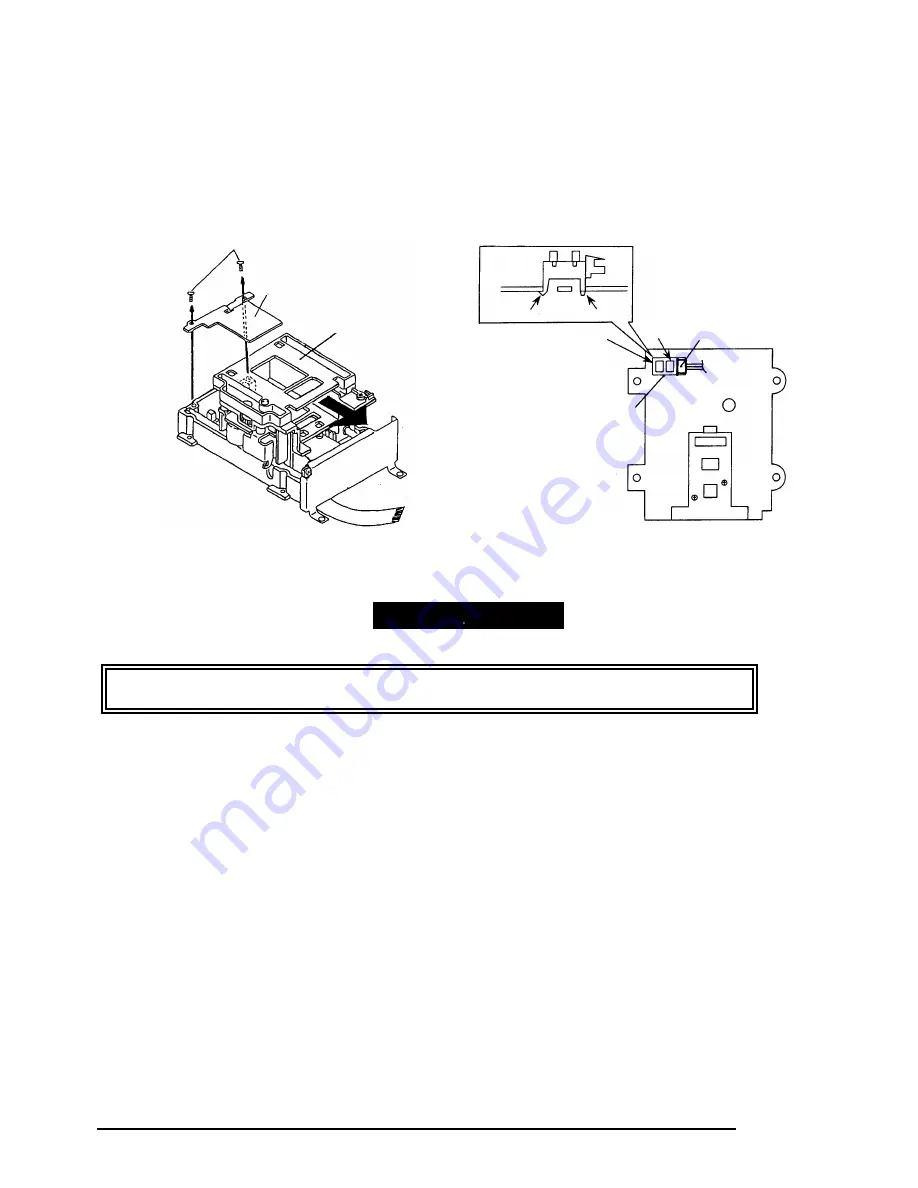
3.2.8.2 Photo Interrupter A Removal
Step 1:
Remove the engine unit (Refer to section 3.2.8.)
Step 2:
Remove the main scan motor unit (Refer to section 3.2.8.1.)
Step 3:
Keep the carrier holder block at backward and remove two CBB (black: M3 x 6) screws that
secure the shaft holding plate B then remove the shaft holding plate B.
Step 4:
Keep the carrier holder block at backward and disconnect the cable connector from the photo
Interrupter A.
Step 5:
Dislocate the hooks of the photo Interrupter A at the back side ((b) then (a) in order), then
take the photo Interrupter A away.
When installing the photo interrupter A, insert the hook (a) and attach to the base, and push the
body of the photo interrupter A then make sure that the hook (b) is locked.
Photo Interrupter A
Insertion Hole (a)
Insertion
Hole (b)
Connector
Hook (a)
Hook (b)
Figure 3-20. Photo Interrupter A Removal (2)
Screw
Shaft Holding Plate A
Carrier Holder Block
Figure 3-19. Photo Interrupter A Removal (1)
ASSEMBLING POINT
Содержание FILMSCAN 200
Страница 1: ...EPSON FILM SCANNER FilmScan 200 SERVICE MANUAL SEIKO EPSON CORPORATION 4007375 ...
Страница 5: ...v REVISION SHEET Revision Issued Data Contents Rev A FEBRUARY 28 1997 First issue ...
Страница 8: ...EPSON SEIKO EPSON CORPORATION ...
Страница 11: ...FilmScan 200 REV A 1 2 The following table shows option Code Name FS1300APS APS Holder Table 1 1 Option ...
Страница 75: ...CHAPTER 4 ADJUSTMENT No adjustment is required in this product ...
Страница 76: ...CHAPTER 5 TROUBLESHOOTING 5 1 PROBLEM ISOLATION 5 1 5 2 SELF DIAGNOSTIC FUNCTION 5 2 5 3 TROUBLESHOOTING 5 3 ...
Страница 85: ...CHAPTER 6 MAINTENENCE 6 1 MAINTENENCE 6 1 6 2 LUBRICATION 6 1 ...
Страница 86: ...APPENDIX A 1 CONNECTOR PIN ASSIGNMENTS 1 A 2 EXPLOED DIAGRAM 8 ...
Страница 88: ...FilmScan 200 Rev A A 2 Figure A 2 Cable Connection SCSI Model ...
Страница 94: ...FilmScan 200 Rev A A 8 A 2 EXPLOED DIAGRAM Figure A 3 FilmScan 200 Bi D Model Exploded Diagram 1 2 ...
Страница 95: ...APPENDIX Rev A A 9 Figure A 4 FilmScan 200 Bi D Model Exploded Diagram 2 2 ...
Страница 96: ...FilmScan 200 Rev A A 10 Figure A 5 FilmScan 200 SCSI Model Exploded Diagram 1 2 ...
Страница 97: ...APPENDIX Rev A A 11 Figure A 6 FilmScan 200 SCSI Model Exploded Diagram 2 2 ...
Страница 98: ...FilmScan 200 Rev A A 12 Figure A 7 APS Holder option Exploded Diagram ...
Страница 100: ...FilmScan 200 Rev A 6 2 Shaft 1 G 36 1 G 36 Figure 6 1 Lubrication Points ...


