


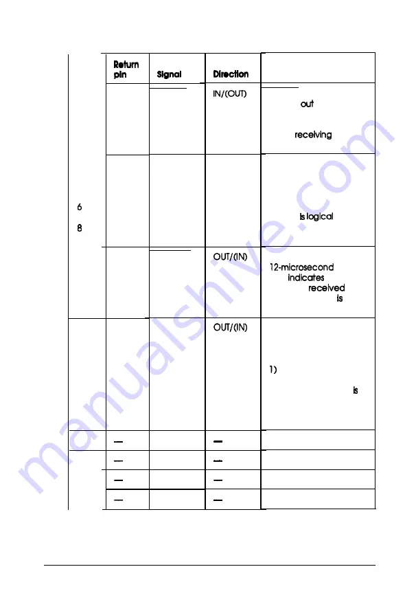
Signal pin assignments
Pin
No.
1
2
3
4
5
7
9
10
11
29
BUSY
12-15
NC
16
17
18
Function
19
STROBE
m
DATA0
IN/OUT
21
DATA1
IN/OUT
22
DATA2
IN/OUT
23
DATA3
IN/OUT
24
DATA4
IN/OUT
25
DATA5
IN/OUT
26
DATA6
IN/OUT
27
DATA7
IN/OUT
28
ACKNLG
About
a
pulse.
Low
that data
has been
and
that the scanner ready
to accept more data.
When this signal is hlgh,
the scanner cannot
receive data. The signal
is high:
during data entry
2) during scanning
3) when the scanner
not ready
4) when the scanner has
an error
Not used
Logical ground level
Scanner chassis ground
Not used
GND
C-GND
NC
STROBE pulse to read In
or send
data. Pulse
width must be more
than 0.5 microseconds
at the
terminal.
These slgnals represent
information of bits 1 to 8
respectively. Each signal
Is at a high level when
data is logical 1 and low
when it
0.
4-6 Technical Specifications
Содержание ES-1200C Pro PC
Страница 1: ...EPSON Scanner User s Guide ...
Страница 46: ...C h a p t e r 3 Troubleshooting Problems and Solutions 3 2 Indicator lights 3 2 Troubleshooting 3 1 ...
Страница 72: ...Appendix Scanner Functions A A 2 How the scanner works r A 2 Scanner settings A 3 Appendix A l ...
Страница 96: ...E p s o n A m e r i c a I n c 20770 Madrona Avenue Torrance California 90503 ...