


CARD-PCI/GX Hardware Manual
EPSON
Rev.A
26
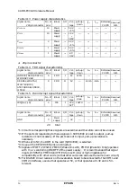
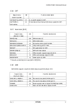
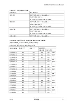
Table 3.13 Power supply characteristics
Signal name
280-pin connector
No. of
pins
Block
I/O
Vol-
tage
I
OL
I
OH
Reference
PU/PD
When not used
PU/PD
V
CCCORE
10
Power
supply
---
5.0V
±
5%
---
---
---
---
---
V
CC3V
10
Power
supply
---
3.3V
±
0.15V
---
---
---
---
---
V
CC5V
2
Power
supply
---
5.0V
±
5%
---
---
---
---
---
V
CCSTB
1
Power
supply
---
5.0V
±
5%
---
---
---
---
---
V
CCBAK
1
Power
supply
---
2.7
∼
3.6V
---
---
---
---
---
♦
20-pin connector
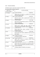
Table 3.14 FDD signal characteristics
Signal name
20-pin connector
No. of
pins
Block
I/O
Vol-
tage
I
OL
I
OH
Reference
PU/PD
When not used
PU/PD
INDEX#,TRK0#,RDATA#,
WP#,DSKCHG#
5
FDD
I
5V
1kPU
---
---
---
---
DENSEL,WDATA#,
WGATE#,DIR#,
STEP#,HDSEL#,DR0#,
MTR0#
8
FDD
O
5V
---
40mA
-4mA
---
---
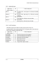
Table 3.15 ISA interrupt signal characteristics
Signal name
20-pin connector
No. of
pins
Block
I/O
Vol-
tage
I
OL
I
OH
Reference
PU/PD
When not used
PU/PD
IRQ[3,4,7,15]
4
ISA
I
3.3V,
5VT
10kPU
---
---
---
---
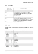
Signal name
20-pin connector
No. of
pins
Block
I/O
Vol-
tage
I
OL
I
OH
Reference
PU/PD
When not used
PU/PD
GND
3
Power
supply
---
0V
---
---
---
---
---
20
total
*1: Circuits corresponding these signals are essential and therefore cannot be unused.
*2: If the ports corresponding to these signals in SCE8720C are set to output, pull-up
resistance is not necessary. If the ports are set to input, pull-up resistance is
necessary.
*3: When set to NC, the ROM in the card (SCE8720C) is selected.
*4: Keep all the RESERVED pins unconnected.
*5: Signals of POFF, PWSW#, PME0# (Wake On LAN), PME1# (Wake On Ring) operates
with V
CCSTB
controlling ON/OFF of the power supply. It is recommended that signal
inputs of PWSW#, PME0# and PME1# are set to low or high impedance for
compatibility with other cards (so that other cards can also use the same main circuit).
*6: For RS232C driver receiver on the evaluation board to be connected to the COM1 and
COM2 interfaces, use one that operates at 5V, or that operates at 3.3V and is 5V-
tolerant.
pull-up/
down
pull-up/
down
pull-up/
down
pull-up/
down


