EPSON AcuLaser C4000/C4100/C3000
Revision F
Disassembly and Assembly
Disassembly Assembly Procedures
4-403
4.2.17 DRIVE
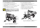
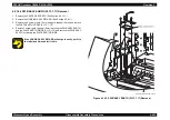
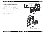
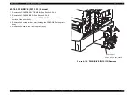
4.2.17.1 DRIVE ASSY DEVE (PL14.1.1) Removal
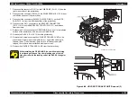
1. Remove the COVER ASSY TOP MAIN. (See Section 4.2.4.4.)
2. Remove the COVER SIDE R. (See Section 4.2.4.9.)
3. Remove the PWB DRIVE. (See Section 4.2.18.5.)
4. Remove the 5 screws (gold, tapped, 10mm) securing the DRIVE ASSY
DEVE from the right side of the printer body.
5. Remove the DRIVE ASSY DEVE from the printer body.
Figure 4-103. DRIVE ASSY DEVE (PL14.1.1) Removal
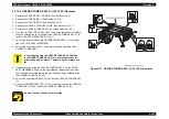
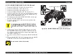
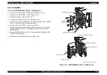
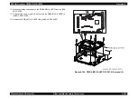
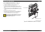
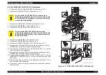
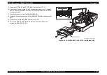
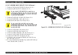
4.2.17.2 DRIVE ASSY MAIN (PL14.1.2) Removal
1. Remove the COVER ASSY TOP MAIN. (See Section 4.2.4.4.)
2. Remove the COVER SIDE R. (See Section 4.2.4.9.)
3. Remove the LINK: R. (See Section 4.2.4.8.)
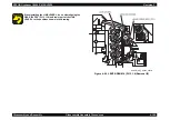
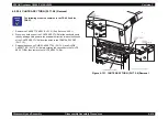
4. Disconnect the connector (P/J48, P/J52) on the PWB DRIVE (PL15.1.15)
from the right side of the printer body.
5. Release the harness (J52) of the FUSER ASSY from the clamp on the
DRIVE ASSY MAIN of the right side of the printer body.
6. Remove the 1 screw (gold, tapped, with outside toothed lock washer,
6mm) securing the ground wire of the lower section of the DRIVE ASSY
MAIN.
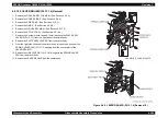
7. Remove the 4 screws (gold, tapped, 10mm) securing the DRIVE ASSY
MAIN to the printer body.
8. Remove the DRIVE ASSY MAIN from the printer body.
Figure 4-104. DRIVE ASSY MAIN (PL14.1.2) Removal
HANABI_BE_CHAP03_074FB
HANABI_BE_CHAP03_075FC
J52
J48
Содержание AcuLaser C3000 Series
Страница 1: ...EPSON AcuLaserC4000 AcuLaserC4100 AcuLaserC3000 Color Laser Page Printer SEPG01012 SERVICE MANUAL ...
Страница 20: ...C H A P T E R 1 PRODUCTDESCRIPTIONS ...
Страница 71: ...C H A P T E R 2 OPERATINGPRINCIPLES ...
Страница 118: ...C H A P T E R 3 TROUBLESHOOTING ...
Страница 318: ...C H A P T E R 4 DISASSEMBLYANDASSEMBLY ...
Страница 472: ...C H A P T E R 5 ADJUSTMENT ...
Страница 477: ...C H A P T E R 6 MAINTENANCE ...
Страница 491: ...C H A P T E R 7 AcuLaserC4100 ...
Страница 548: ......
Страница 549: ......
Страница 550: ......
Страница 551: ......
Страница 552: ......
Страница 553: ......
Страница 554: ......
Страница 555: ...C H A P T E R 8 AcuLaserC3000 ...
Страница 579: ...Model AcuLaser C3000 Board C569MAIN BOARD Sheet 1 of 5 Rev B ...
Страница 580: ...Model AcuLaser C3000 Board C569MAIN BOARD Sheet 2 of 5 Rev B ...
Страница 581: ...Model AcuLaser C3000 Board C569MAIN BOARD Sheet 3 of 5 Rev B ...
Страница 582: ...Model AcuLaser C3000 Board C569MAIN BOARD Sheet 4 of 5 Rev B ...
Страница 583: ...Model AcuLaser C3000 Board C569MAIN BOARD Sheet 5 of 5 Rev B ...
Страница 584: ...C H A P T E R 9 APPENDIX ...
Страница 617: ...EPSON AcuLaser C4000 C4100 C3000 Revision F Appendix Wiring Diagrams 9 602 Figure 9 6 P J Location 6 ...
Страница 644: ...EPSON AcuLaser C4000 C4100 C3000 Revision F Appendix Wiring Diagrams and Signal Information 9 629 ...
Страница 674: ......
Страница 675: ......
Страница 676: ......
Страница 677: ......
Страница 678: ......
Страница 679: ......
Страница 680: ......


