EPSON AcuLaser C4000/C4100/C3000
Revision F
Disassembly and Assembly
Disassembly Assembly Procedures
4-315
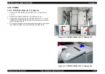
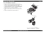
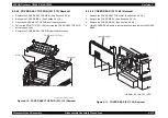
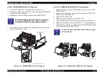
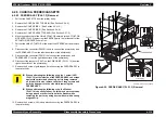
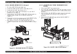
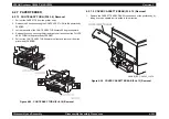
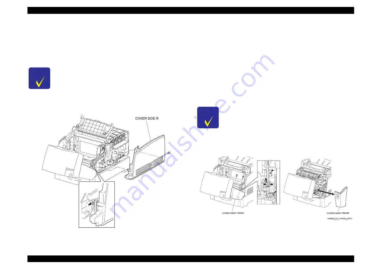
4.2.4.9 COVER SIDE R (PL1.2.2) Removal
1. Remove the COVER ASSY TOP MAIN. (See Section 4.2.4.4.)
2. Remove the 1 screw (silver, with a brim, 8mm) securing the COVER SIDE
R to the rear of the printer body.
3. Release the 1 hook securing the front side of the COVER SIDE R.
4. Lift the upper part of the COVER SIDE R while pulling it to the right, then
remove it from the printer body.
Figure 4-14. COVER SIDE R (PL1.2.2) Removal
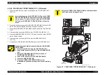
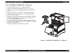
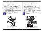
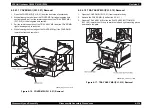
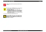
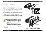
4.2.4.10 COVER ASSY FRONT (PL1.2.6) Removal
1. Release the latch A and open CHUTE ASSY OUT (PL7.1) and CHUTE
ASSY IN (PL6.1.1).
2. Remove the 2 screws (gold, tapped, 10mm) securing the COVER ASSY
FRONT to the CHUTE ASSY IN .
3. Close the CHUTE ASSY OUT.
4. Release the latch B and open CHUTE ASSY OUT.
5. Pull the COVER ASSY FRONT a little ways from the CHUTE ASSY IN.
6. Release the boss at the front of the LINK:R (PL 1.2.5) with spreading the
SPRING PLATE LINK (PL 1.2.8) at the back of the COVER ASSY FRONT.
Then remove the COVER ASSY FRONT.
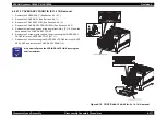
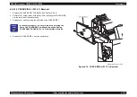
Figure 4-15. COVER ASSY FRONT (PL1.2.6) Removal
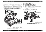
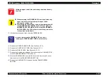
C H E C K
P O I N T
In the next procedure, it is easy to remove by moving the
front of the COVER SIDE R with pushing and spreading
COVER ASSY FRONT (PL 1.2.6) to outside a little bit.
HANABI_BE_CHAP03_018FC
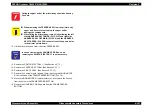
C H E C K
P O I N T
It is better to Spread the SPRING PLATE LINK by using the
small screwdriver.
LINK R
Содержание AcuLaser C3000 Series
Страница 1: ...EPSON AcuLaserC4000 AcuLaserC4100 AcuLaserC3000 Color Laser Page Printer SEPG01012 SERVICE MANUAL ...
Страница 20: ...C H A P T E R 1 PRODUCTDESCRIPTIONS ...
Страница 71: ...C H A P T E R 2 OPERATINGPRINCIPLES ...
Страница 118: ...C H A P T E R 3 TROUBLESHOOTING ...
Страница 318: ...C H A P T E R 4 DISASSEMBLYANDASSEMBLY ...
Страница 472: ...C H A P T E R 5 ADJUSTMENT ...
Страница 477: ...C H A P T E R 6 MAINTENANCE ...
Страница 491: ...C H A P T E R 7 AcuLaserC4100 ...
Страница 548: ......
Страница 549: ......
Страница 550: ......
Страница 551: ......
Страница 552: ......
Страница 553: ......
Страница 554: ......
Страница 555: ...C H A P T E R 8 AcuLaserC3000 ...
Страница 579: ...Model AcuLaser C3000 Board C569MAIN BOARD Sheet 1 of 5 Rev B ...
Страница 580: ...Model AcuLaser C3000 Board C569MAIN BOARD Sheet 2 of 5 Rev B ...
Страница 581: ...Model AcuLaser C3000 Board C569MAIN BOARD Sheet 3 of 5 Rev B ...
Страница 582: ...Model AcuLaser C3000 Board C569MAIN BOARD Sheet 4 of 5 Rev B ...
Страница 583: ...Model AcuLaser C3000 Board C569MAIN BOARD Sheet 5 of 5 Rev B ...
Страница 584: ...C H A P T E R 9 APPENDIX ...
Страница 617: ...EPSON AcuLaser C4000 C4100 C3000 Revision F Appendix Wiring Diagrams 9 602 Figure 9 6 P J Location 6 ...
Страница 644: ...EPSON AcuLaser C4000 C4100 C3000 Revision F Appendix Wiring Diagrams and Signal Information 9 629 ...
Страница 674: ......
Страница 675: ......
Страница 676: ......
Страница 677: ......
Страница 678: ......
Страница 679: ......
Страница 680: ......


