background image

EPSON AcuLaser C4000/C4100/C3000

Revision F

Disassembly and Assembly

Disassembly Assembly Procedures

4-314

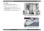
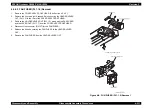
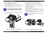
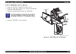
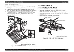
4.2.4.7  LINK: L (PL1.2.5) Removal

1. Remove the COVER ASSY TOP MAIN. (See Section 4.2.4.4.)

2. Remove the COVER SIDE L. (See Section 4.2.4.14.)

3. Spread the SPRING PLATE LINK (PL 1.2.8) on the rear of the COVER 

FRONT IN (PL 1.2.10), then release the boss of the LINK;L.

4. At the left side of the printer body, release the hook of the SPRING LINK: L 

(PL1.2.4) from the convex surface.

5. Slide the LINK: L toward the rear of the printer, then align the axle of the 

printer body with the hole of the LINK: L.

6. Remove the LINK: L along with the SPRING LINK: L from the printer body.

7. Remove the SPRING LINK: L from the LINK: L.

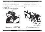
Figure 4-12.  LINK: L (PL1.2.5) Removal

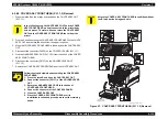
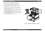
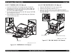
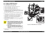
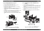
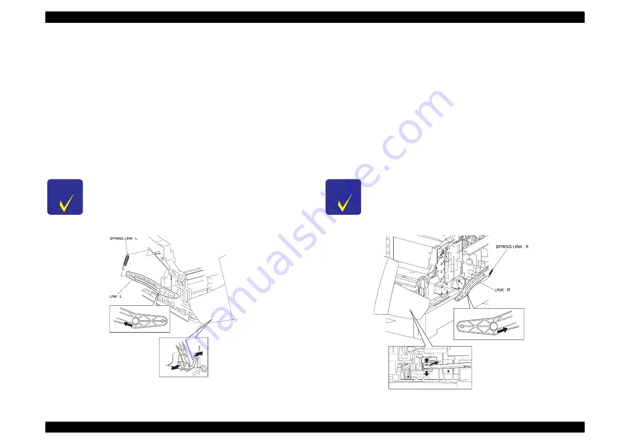
4.2.4.8  LINK: R (PL1.2.5) Removal

1. Remove the COVER ASSY TOP MAIN. (See Section 4.2.4.4.)

2. Remove the COVER SIDE R. (See Section 4.2.4.9.)

3. Spread the SPRING PLATE LINK (PL 1.2.9) on the rear of the CONVER 

FRONT (PL 1.2.9), then release the boss of the LINK;R.

4. At the right side of the printer, pull out the hook of the SPRING LINK: R 

(PL1.2.4) from the convex surface.

5. Slide the LINK: R toward the rear of the printer, then align the axle of the 

printer body with the hole of the LINK: R.

6. Remove the LINK: R along with the SPRING LINK: R from the printer body.

7. Remove the SPRING LINK: R from the LINK: R.

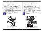
Figure 4-13.  LINK: R (PL1.2.5) Removal

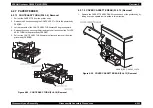
C H E C K

P O I N T

It is better to Spread the SPRING PLATE LINK by using the 
small screwdriver.

HANABI_BE_CHAP03_109FB

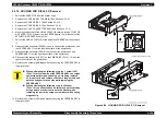
C H E C K

P O I N T

It is better to Spread the SPRING PLATE LINK by using the 
small screwdriver.

HANABI_BE_CHAP03_108FB

Содержание AcuLaser C3000 Series

Страница 1: ...EPSON AcuLaserC4000 AcuLaserC4100 AcuLaserC3000 Color Laser Page Printer SEPG01012 SERVICE MANUAL ...

Страница 2: ... should any errors be detected SEIKO EPSON would greatly appreciate being informed of them The above not withstanding SEIKO EPSON CORPORATION can assume no responsibility for any errors in this manual or the consequences thereof EPSON is a registered trademark of SEIKO EPSON CORPORATION General Notice Other product names used herein are for identification purpose only and may be trademarks or regi...

Страница 3: ...E MUST BE CONNECTED USE EXTREME CAUTION IN WORKING ON POWER SUPPLY AND OTHER ELECTRONIC COMPONENTS 4 WHEN DISASSEMBLING OR ASSEMBLING A PRODUCT BE SURE TO WEAR GLOVES TO AVOID INJURIES FROM METAL PARTS WITH SHARP EDGES WARNING 1 REPAIRS ON EPSON PRODUCT SHOULD BE PERFORMED ONLY BY AN EPSON CERTIFIED REPAIR TECHNICIAN 2 MAKE CERTAIN THAT THE SOURCE VOLTAGES IS THE SAME AS THE RATED VOLTAGE LISTED O...

Страница 4: ...hanical operations maintenance and repair procedures of the EPSON AcuLaser C4000 AcuLaser C4100 and AcuLaser C3000 The instructions and procedures included herein are intended for the experienced repair technicians and attention should be given to the precautions on the preceding page ...

Страница 5: ... to provide additional information on a specific topic or to warn of possible danger present during a procedure or an action Be aware of all symbols when they are used and always read NOTE CAUTION or WARNING messages Indicates an operating or maintenance procedure practice or condition that is necessary to keep the product s quality Indicates an operating or maintenance procedure practice or condi...

Страница 6: ...ssy Assembly Aux Auxiliary B B W Black and White BCR Bias Charge Roll Bk Black BCR Bias Charge Roll BRKT Bracket BTR Bias Transfer Roll BUR Back Up Roll C C Cyan CCW Counter Clockwise Cl Clutch Clk Clock CHK Check CK Check Conpane Control Panel Cont Controller CR Charge Roll CRU Customer Replaceable Unit CRUM CRU Memory CST Cassette CVR Cover CW Clockwise D DB Developing Bias Deve Developer Diag D...

Страница 7: ...Paper Handling P R Pressure Roll PL Plate PLT Plate PPM Print Per Minute PV Print Volume PWB Printed Wiring Board PWBA PWB Assembly R R Right R Rear R H Right Hand RDY Ready Regi Registration ROS Raster Output Scanner RRP Removal and Replacement Procedure RTN Return S SEF Short Edge Feed SG Signal Ground SNR Sensor SNS Sensor Sol Solenoid SOS Start Of Scan SPI Scan Per Inch STD Stamdard STK Stacke...

Страница 8: ... with the printer Power Supply Before starting any service procedure switch off the printer power and unplug the power cord from the wall outlet If you must service the printer when the power is applied be aware of the potential for electrical shock and do all tasks by following the procedures in this manual Figure 0 1 Power Supply W A R N I N G Do not touch any live part unless you are instructed...

Страница 9: ...burned do the following Before working with a high temperature Assembly e g Fuser Assembly turn off the power unplug the power cord and wait until it cools down W A R N I N G Do not touch the driving part e g gears while the assembly printer is being driven W A R N I N G The high temperature Assembly is very hot immediately after any printer operations Wait at least 40 minutes before you start wor...

Страница 10: ...erature A laser beam is harmful to the human body NOTE The laser beam in this printer is invisible Figure 0 2 Laser Beam W A R N I N G Do not expose yourself to the laser beam to prevent injury blindness Do not open the cover that has the laser beam warning label If you disassemble or assemble the printer turn off the power If you need to work on the printer with power applied strictly follow the ...

Страница 11: ...ls and Caution labels are placed on the printer to help prevent accidents When maintaining the printer confirm that these labels are not dirty or peeling off Caution label for high temperature components Figure 0 3 Warning and Caution Labels ...

Страница 12: ...Safety System Schematic The schematic below outlines the features of the printer s safety system For details about signal wires see Appendix Wiring Diagram ...

Страница 13: ...pter 1 PRODUCT DESCRIPTIONS Chapter 2 OPERATING PRINCIPLES Chapter 3 TROUBLESHOOTING Chapter 4 DISASSEMBLY AND ASSEMBLY Chapter 5 ADJUSTMENT Chapter 6 MAINTENANCE Chapter 7 AcuLaser C4100 Chapter 8 AcuLaser C3000 Appendix ...

Страница 14: ...FIP 28 Fuser Life Over is added FIP 48 Engine Communication Error is added FIP 49 Verify DIMM Slot Related Error is added FIP 50 Error in Standard RAM Slot 0 1 is added FIP 51 ROM Checksum Error MASK ROM for Font is added FIP 52 ROM Checksum Error CODE IPL is added FIP 53 ROM Module DIMM Slot A Related Error is added FIP 54 EEPROM Writing Error is added FIP 55 CCNV Hardware Error is added FIP 56 E...

Страница 15: ...rt of text is revised Chapter 6 6 1 2 Consumable components and components that require regular replacement The value of Transfer Unit Lifetime is revised The parts code of Roll Assy is fixed Chapter 7 Additional information added for AcuLaser C4100 E August 19 2004 Revision up Chapter 8 Additional information added for AcuLaser C3000 F October 26 2004 Revision up Chapter 1 1 5 2 Durability 1 19 t...

Страница 16: ...terface Specifications 28 Control Panel 33 Exterior View and Names 33 Display Elements Description 34 Button Functions Description 35 Special Operations 36 Panel Setting Item List 37 Explanation of Each Setting Menu and Setting Items 47 About RAM Expansion 54 Dimensions 54 Operating Principles Print Process 56 Print Process Overview 56 Print Process Diagram 57 Print Process Technical Explanation 5...

Страница 17: ...03 Preliminary Checks 103 Precautions When Performing Work 104 Test print by engine itself 105 Precautions When Using FIP 106 Level 1 FIP 107 Level 1 FIP Flowchart 107 Level 2 FIP 108 Level 2 FIP 108 Self Diagnostic Function by LCD Message 108 Service Call Error Messages 118 Image Quality Troubleshooting FIP 246 Printer Operation Troubleshooting FIP 267 Other FIP 279 Level 2 FIP Large Capacity Pap...

Страница 18: ... List of Printer Messages 496 Details of Error Message and Treatment 497 Details of Warning Message and Treatment 498 Maintenance 499 Consumable components and regularly replaced parts 499 Engine Status Sheet 502 List of control information and control methods 503 Parts List for AL C4100 504 Exploded Diagram 508 Circuit Schematic 532 AcuLaser C3000 Product Descriptions 541 Features 541 Printer Bas...

Страница 19: ...he part list 637 Parts List Tables 638 Exploded Diagrams 639 Wiring Diagrams 644 P J Locations 644 Plug and Jack P J Location Tables 645 Wiring Diagrams and Signal Information 646 Overall Wiring Connection Diagram 646 Wiring and Signal Descriptions between Components 648 Notation on the Diagrams for the Wiring and Signal Descriptions between Components 649 Component Layout 656 Circuit Diagrams 658...

Страница 20: ...C H A P T E R 1 PRODUCTDESCRIPTIONS ...

Страница 21: ...ollowing 2 bin the MP Tray up to 100 sheets and the Lower Cassette up to 500 sheets A4 LT By adding the two optional Lower Cassette up to 500 sheets 2 cassettes A4 LT a maximum of 1600 sheets can be fed from the 4 bin in total 7 Standard paper eject is up to 250 sheets into the Face down tray CONTROLLER FEATURES 1 High speed controller with a new CPU adopted 64 bit RISC CPU PowerPC 750CX 400 MHz 6...

Страница 22: ...thernet I F Font registration in the PostScript3 mode Registration of Reserve Job and Confidential Job Registering Form Overlay only available for Windows environment 6 Changing the Manual Feed specification Same as EPL 5900 7 Installed emulation Standard ESC Page Color PCL5e B W GL Like B W FX B W ESCP2 B W I239X B W ESC Page B W Options Adobe Postscript3 Others EJL PJL mode RCC mode firmware upd...

Страница 23: ...e belt nip method 1 2 1 2 Printer Basic Specification METHOD Electrophotographic method using scanning semiconductor laser beam and dry two component toner RESOLUTION 600dpi and 1 200dpi WARMING UP TIME 30 or less seconds when printer is powered on or standby mode 22 C 55 RH environment at rated voltage PRINT MODE 600dpi Mode Normal paper Full speed 600dpi Mode Special paper Low speed 1200dpi Mode...

Страница 24: ...aper L mode Thick paper 100 159g m2 Thick2 Heavier paper H mode Thick paper 160g 216m2 Label low temp Label L mode Label Label high temp Label H mode Label OHP OHP mode OHP films Envelope Envelope mode Envelope Table 1 2 First Printing Time Standard Optional Feeder 500 Sheets Unit MP Tray Cassette 1 Cassette 2 Cassette 3 A4 SEF Simplex Printing 15 0 15 5 17 0 18 5 24 0 24 5 27 5 30 5 Duplex Printi...

Страница 25: ...88 9 x 139 7 mm Max size 215 9 x 355 6 mm Standard Paper Normal Paper 1 Sheet 900mm in length Standard Paper Normal Paper TBD Sheets A4 LT Special Applications Labels Transparencies TBD Sheets Official Postcard 190 g m2 TBD Sheets 10mm Envelopes Monarch C10 DL C5 C6 5 ISO B5 5 Yokei 2 3 4 Youchoukei 3 5 Unspecified size Min size 90mm width 143mm length with flap opened Cassette 500 sheets 2 3 58mm...

Страница 26: ... Feed the long edge of the paper is fed to the printer SEF Short Edge Feed the short edge of the paper is fed to the printer Unsupported Table 1 6 Applicable Paper Sizes Paper Types and Paper Orientation 1 Paper Size Dimensions in mm inches Standard Optional DuplexPrinting 3 Paper Orientation MP Tray cassette 500 Sheets 500 Sheets Unit 2 Normal Paper A4 210 00 x 297 00 SEF A5 6 148 00 x 210 00 SEF...

Страница 27: ...g Edge Feed the long edge of the paper is fed to the printer SEF Short Edge Feed the short edge of the paper is fed to the printer Unsupported Table 1 7 Applicable Paper Sizes Paper Types and Paper Orientation 2 Paper Size Dimensions in mm inches Standard Optional Duplex Printing 3 Paper Orientation Paper Tray cassette 500 Sheets 500 Sheets Unit 2 Special Applications Official Postcard 4 100 00 x ...

Страница 28: ...t Same specification as cassette of the main unit OUTPUT PAPER CAPACITY Maximum of 250 sheets to face down tray at 22 C 55 RH standard paper DIMENSIONS Stand Alone Outline Dimensions and Weights Unit mm kg NOTE 1 Unpacked dimensions are stated NOTE 2 Dimensions has 1 mm difference weights are 1 kg difference NOTE 3 Main unit weights do not including consumable items Outline Dimensions and Weights ...

Страница 29: ...ment See Components that require regular replacement on Page 13 NOISE NOTE 1 Values measured by ISO7779 9 point method NOTE 2 Measured with MP tray closed NOTE 3 Simplex and duplex printing are the same values EMISSION Ozone Concentration 0 01ppm or less New Blue Angel standard compliance Dust Concentration 0 1mg m3 HAZARDOUS MATERIALS None of the OPC toner or plastic contains hazardous materials ...

Страница 30: ...detection Near life end Sensor detection Refer to 2 Work life end Softcounter Refer to 2 Fuser Unit Cartridge mounted unmounted Automatic detection Near life end Softcounter Refer to 2 Work life end Softcounter Refer to 2 Standard Paper Feeder MP Tray Paper size Automatic detection Out of Paper Automatic detection by Photo Sensor and Mechanical Lever Cassette Cassette mounted unmounted Automatic d...

Страница 31: ...vate when either the page count or the Dispense Time for any color is reached 8 After replacement resetting the item in the control panel will detect the new part 9 The shape of cartridge housing is unique to each color and this prevents it from installing on the wrong cartridge holder NOTE Dispense Time is a controller count value Units are seconds Name Detection Near end End Engine stop 3 Toner ...

Страница 32: ...pecial coatings or colored printer paper with processed surfaces Glossy too slick on its surface paper or paper with too smooth rough surfaces Paper with significantly different roughness on each surface Paper with punch holes or perforations Creased curled or torn paper Irregularly shaped paper or paper with non perpendicular corners Labels that peel off easily Paper with glue staples or paper cl...

Страница 33: ... be fed 1 4 4 Printing Area PRINTABLE AREA 210 9 x 351 6 210 9 x 896 0 at the time of setting uncut paper GUARANTEED PRINTING AREA Area with a margin of 4 mm from each side Refer to the following figure Uncut paper is not applicable Figure 1 2 Guaranteed Print Area Table 1 12 Paper Usability for Each Paper Source Standard Paper Normal paper Special Applications Transparencies Official Postcard Lab...

Страница 34: ...ndary between original paper and replenished paper occurring after paper is replenished PRINTING START POSITION ACCURACY With standard paper fed from MP tray or paper cassette Reference point of main scanning direction c 2 5mm Reference point of sub scanning direction a 2 0mm Figure 1 3 Print Position Accuracy Table 1 13 Paper Jam Rate Paper Type Standard MP Tray Standard Cassette and Optional 500...

Страница 35: ...1 5 3 Maintenance MTTR Averages within 30 minutes 95 is complete within 50 minutes Time for examining malfunction is not included time required for service personnel to determine and correct the cause of the malfunction Table 1 15 Paper Skew Printing Page Scanning Direction A4 Simplex Main Scanning Direction a b 1 23 Sub Scanning Direction c d 1 78 Duplex Main Scanning Direction a b Sub Scanning D...

Страница 36: ...r less no exposure to direct sunlight SPACE REQUIREMENTS In order to ensure that the printer operates properly provide at least as much space as shown in the diagram below To open the cover and be able to replace the consumables easily provide at least 350 mm of space above the top of the printer Figure 1 4 Space Requirement Table 1 17 Air Temperature and Humidity Temperature C Humidity RH Others ...

Страница 37: ...f application 50 minutes along each X Y Z axis total of 150 minutes Table 1 18 Temperature and Humidity Temperature C Humidity RH Warranty Period Altitude m Others Normal Conditions 0 to 35 15 to 80 12 months 0 to 3 100 No condensation allowed Severe Conditions High temperature 35 to 40 Low temperature 20 to 0 High humidity 80 to 95 Low humidity 5 to 15 Maximum of 48 hours Table 1 19 Temperature a...

Страница 38: ...EN61000 2 IEC1000 4 2 1995 compliance No malfunction such as defective image quality or no errors allowed even if 4kv of static electricity noise is in contact discharge INRUSH CURRENT 0 5 cycle 100 A or less The time of heater inrush is included INSULATION RESISTANCE 10MΩ or more DIELECTRIC STRENGTH No break down during application of the voltages shown below for a one minute period LEAK CURRENT ...

Страница 39: ... OSHA compliance Ozone generation Conform to UL 478 5th printing Materials Swiss Environmental Protection Standards compliance contains no Cds 1 10 Consumable Components SPECIFICATIONS 1 The number of sheets is the approximate number of printable images using A4 landscape continuous printing at 5 image occupation rate The first cartridge will Near End for TBD page count In order to fill the develo...

Страница 40: ...mensional Time of application 50 minutes along each X Y Z axis total of 150 minutes 1 11 Maintenance Table 1 24 Temperature Humidity Conditions Temperature Humidity Warranty Period Normal 0 to 35 C 15 to 80 24 months Severe High temp 35 to 45 C 80 to 95 Maximum of one month Low temp 20 to 0 C 5 to 15 Table 1 25 Dropping Dropping Height cm Dropping Direction Consumables 91 0 1 corner 3 edges 6 side...

Страница 41: ...s Figure 1 5 Exterior view and Unit parts 1 Table 1 27 Exterior View and Unit Parts No Part name 1 Control panel 2 Top cover 3 Output tray 4 Power switch 5 Latch on cover A 6 Latch on cover B 7 Standard lower cassette 8 MP tray Multi Purpose tray 9 Expansion tray 10 Large capacity paper unit option 11 AC inlet 12 Stopper 13 Interface card slot cover 14 Ethernet interface connector 15 Parallel inte...

Страница 42: ...EPSON AcuLaser C4000 C4100 C3000 Revision F Product Descriptions Exterior View and Unit Names 1 26 Figure 1 6 Exterior view and Unit parts 2 Figure 1 7 Exterior view and Unit parts 3 ...

Страница 43: ...two slots by installing 512MB NOTE The standard 64 MB RAM must be removed ROM 32 bit width Program 4 MB Flash ROM DIMM Fonts 4 MB Expansion ROM 1 slot ROM DIMM slot can be installed and removed only when turning off the printer A slot PS3 font ROM module HOST INTERFACE Standard Parallel 1ch Bi directional compatible with IEEE 1284 standard B type connector Compatibility Nibble ECP Ethernet 100 Bas...

Страница 44: ... for North South America LT is set Other destinations A4 is set 1 13 3 External Interface Specifications This printer is equipped with the following host interfaces 1 Parallel Interface Standard 2 Ethernet Interface Standard 3 USB 1 1 Interface Standard 4 Optional Interface Type B 1 slot The positions of the respective interfaces are shown in the Figure 1 8 Figure 1 8 Positions of Host Interface E...

Страница 45: ...cluded The CMD items are in random order MODE and STATUS items are excluded The contents of DES items consist of MFG and MDL connected by a space MFG EPSON CMD PJL EJL ESCPL2 ESCP9 PRPXL24 01 PCL HPGL2 01 ESCPAGE 04 ESCPAGECOLOR 01 1 MDL 2 CLS PRINTER DES EPSON 2 1 POSTSCRIPT is added only when the PostScript 3 module is installed 2 AL C4000 Furthermore the user can redefine the Device ID MFG MDL ...

Страница 46: ...Talk IPP Internet Printing Protocol MANAGEMENT PROTOCOLS 1 TCP IP SNMP ENPC HTTP TELNET DHCP BOOTP PING 2 Microsoft Network Auto IP SSDP 3 NetBEUI SNMP ENPC 4 NetWare SNMP ENPC 5 AppleTalk SNMP ENPC ENPC EPSON Network Peripheral Control Protocol Table 1 28 Centronics Parallel Interface Pin Assignment Pin I O Signal Names Pin I O Signal Names 1 I STRBX 19 GND 2 I O D1 20 GND 3 I O D2 21 GND 4 I O D...

Страница 47: ... USB1 1 The value for this ID is printed on the bottom of the Status Sheet Each digit denotes information as shown below P YYMMDDhhmmssR Model unique number from 00 to 99 11 for this printer P Identifier indicating page printer Always P for page printers PC number of the assembly belt 00 to 99 YY Year of assembly lower 2 digit 00 to 99 MM Month of assembly 1 to 12 DD Day of assembly 0 to 31 HH Hou...

Страница 48: ... is set to AUTO If PS is not started AUTO Emulation Types 1 2 3 If PS is started EJL POSTSCRIPT 00 other Emulation Types 1 2 3 When Emulation is fixed EJL Default Emulation Type other Emulation Types 1 2 3 Entity Type When Emulation is set to AUTO Refer to the above list When Emulation is fixed The default Emulation Type and EPSONPAGECOLOR1 are returned Table 1 31 Emulation Type Entity Type Emulat...

Страница 49: ...The key assignment of password is shown on the label for each bundling Table 1 32 LEDs and switches on the Control Panel Location Name Remarks 1 LCD Panel 1 line x 20 digit 5 x 7 dot matrix 2 Back button 1 for password input 1 3 Up button 2 for password input 1 4 Enter button 3 for password input 1 5 Down button 4 for password input 1 6 Job Cancel button 7 Data light Color yellow 8 Ready light Col...

Страница 50: ... is receiving or processing data READY LIGHT 8 ON Indicates that the printer is ready to print OFF Indicates that the printer cannot print Error condition In an error occurrence printing is disabled switching off the On Line light ERROR LIGHT 9 FLASH 1 An error where printing continues if the Start Stop button is pressed has occured FLASH 2 An error where an operator must release the error and pre...

Страница 51: ...he panel setting mode Displays the value next to the currentlyselected hierarchy menus items or values JOB CANCEL BUTTON 6 Normal pressing Deletes currently printed data Every time pressing this button deletes the job Long pressing two seconds or longer Deletes all data such as data in the print queue jobs and data that are currently being received and printing data that are being processed START ...

Страница 52: ...lot A After this a warm boot is performed and the printer will return to normal status PROGRAM ROM UPDATE This function updates the flash ROM module that has been inserted into the programming socket Table 1 33 List of Operating Functions Function Operating Method Hex Dump Turn the power on pressing the Start Stop button Support Mode Turn the power on pressing the Down button Initialization of EEP...

Страница 53: ...14 5 Panel Setting Item List This printer s setting item list is shown below Furthermore the factory defaults values are shown in Bold style INFORMATION MENU 1 This is displayed only when a Job is registered in the Quick Print Job 2 This is displayed and can be executed only when the Form Overlay is implemented 3 This is displayed and can be executed only when the Network I F On 4 This is displaye...

Страница 54: ...roller and A4 is the default value of the A4 type controller 2 Paper sizes width x length for CTM Custom are min 88 9 x 139 7 mm and max 215 9 x 355 6 mm Item Value MP Tray Size A4 1 A5 B5 LT 1 HLT LGL GLT GLG EXE F4 MON C10 DL C5 C6 IB5 LC1 Size 2 A4 A5 B5 LT LGL GLG EXE LC2 Size 2 3 A4 A5 B5 LT LGL GLG EXE LC3 Size 2 3 A4 A5 B5 LT LGL GLG EXE MP Type Plain Letterhead Recycled Color Trnsprncy Lab...

Страница 55: ...on when the User is displayed this Item appears 3 By selecting the Value Job name and pressing the Enter button when the Job is displayed this Item appears and can be selected and executed After executing this Item the printer return to the status when recovering from the SelecType mode 4 After activating Delete display will return to Job If there is no Job display will return to User If there is ...

Страница 56: ...ob display will return to User If there is no User display will return to previous condition after escaping from Select Type RESET MENU PARALLEL MENU 1 1 When this setting is changed the setting value becomes valid after warm boot or restarting the printer The setting value is reflected immediately to the Status Sheet and EJL read back however it is changed in practice after warm boot or restartin...

Страница 57: ...ce is installed 3 This is displayed and can be selected executed only when Level 3 compatible Type B host interface is installed This automatically returns to AUX Config No when the printer status changed to Online Item Value Network I F On Off Network Config No Yes Get IPAddress 2 Panel Auto PING IP Byte 1 2 3 0 192 255 IP Byte 2 2 3 0 168 255 IP Byte 3 2 3 0 192 255 IP Byte 4 2 3 0 168 255 SM By...

Страница 58: ...ting value executing AUX Status Sheet of the Test print menu before recovering from the Panel setting mode prints the previous setting value 5 This is not displayed when Get IPAddress Auto ESC PAGE MENU 1 1 This is not displayed on the panel or the Status Sheet It can be specified in EJL Item Value Auto CR On Off Auto FF On Off CR Function CR CR LF LF Function CR LF LF FF Function CR FF FF Error C...

Страница 59: ...e of Font Source and Font Number to a font that supports this Symbol Set Item Value Font Source Resident Download 1 ROM A 2 Font Number 0 available Max 65535 Pitch 3 0 44 10 00 99 99 cpi step 0 01 cpi Height 3 4 00 12 00 999 75 pt step 0 25 pt SymSet IBM US ECM94 1 8859 10ISO IBM DN PcTk437 WiAnsi WiBALT VeInternati Math 8 PiFont ANSI ASCII Spanish French2 PcIcelandic PcPortugues PcCanFrench 8859 ...

Страница 60: ... 0 05 0 35 5 00 mm step 0 05 mm Pen6 1 0 05 0 35 5 00 mm step 0 05 mm Item Value Error Sheet Off On Coloration Color Mono TrueCol Image Protect Off On Item Value Font Courier Prestige Roman Sans serif Roman T Orator S Sans H Script OCR A OCR B Pitch 10 cpi 12 cpi 15 cpi Prop Condensed Off On T Margin 0 40 0 50 1 50 inch step 0 05 inch Text 1 62 1 66 1 available Max 67 Lines CGTable PcUSA Italic Pc...

Страница 61: ...e Max 81 Lines CGTable PcUSA PcPortugue PcTurkish2 BpBRASCII PcEur858 Italic PcCanFrenc Pclcelandic BpAbicomp ISO Latin1 PcMultilin PcNordic PcE Europe Roman 8 8859 15ISO Country USA France Germany UK Denmark Sweden Italy Spain1 Japan Norway Denmark2 Spain2 LatinAmeric Auto CR On Off Auto LF Off On Bit Image Dark Light Barcode ZeroChar 0 Ø Item Value Font Courier Prestige Gothic Orator Script Pres...

Страница 62: ... Transfer Unit are replaced before life end The printer is rebooted after executing this menu MAINTENANCE MENU 1 1 This setting menu is displayed only when the Maintenance Mode has been activated by hidden operation when the power is turned on Always displayed in English regardless of the Lang setting in the Setup Menu A list of user setting items which are not included in the Setup Menu are shown...

Страница 63: ...LCD blinks when printing is in progress C TONER The remaining C Cyan toner level is displayed in 5 steps display only exclusive readout E F 100 Remaining Toner 75 E F 75 Remaining Toner 50 E F 50 Remaining Toner 25 E F 25 Remaining Toner 0 E F Remaining Toner 0 Reference This cannot be included in the manual The remaining toner is displayed according to the Dispense Time 3 050 Sec 0 that is admini...

Страница 64: ...nted by the printer up to present display only B W PAGES This displays only the number of sheets printed in monochrome by the printer up to present display only 1 14 6 2 Tray Menu MP TYPE LC1 TYPE LC2 TYPE LC3 TYPE This menu specifies the type of paper set in the MP Tray LC1 2 3 Cassette When Paper Size envelopes IB5 C10 C5 DL MON C6 the Paper Source used is always the MP tray Engine control is pe...

Страница 65: ...by the CRIT function TONER SAVE During color printing by controlling the halftone growth and by printing with a low density toner consumption is reduced 1 14 6 4 Setup Menu PAPER SOURCE Selects the paper source when Paper Type Normal Auto Feeds paper from the paper source that loads paper of the specified paper type and paper size MP Feeds paper from the MP Tray LC1 Feeds paper from the LC1 LC2 Fe...

Страница 66: ...ideo Media Type CM Envelope 1 Envelope Plain Paper Other Than Envelope Normal Auto Specified Plain Letterhead Recycled Color Thicker paper H See Table 1 36 Trnsprnc Transparency See Table 1 36 Labels Heavier paper L See Table 1 36 Not Specified Thicker paper H See Table 1 37 Other Than Auto Thicker paper H See Table 1 37 Thick FRONT Heavier paper L Plain Paper BACK Heavier paper L Back Plain Paper...

Страница 67: ... setting value is set to 0 and the display is too light to be visible initialize the panel setting by restarting the printer pressing the Job Cancel button CYAN MAGENTA YELLOW REGIST This menu adjusts the registration of laser scan printing position for Black in 1 dot unit of 600 dpi The adjustment is made when primarily locating the main unit and when moving it Additionally the adjustment is perf...

Страница 68: ...of 5 The current changes 5 for each step 0 for default Printing result is lightest when 15 is set and darkest when 15 is set THICK Sets the Transfer Current for printing with the PaperType Thick setting The rest of processing is same as Normal EXTRATHK Sets the Transfer Current for printing with the PaperType ExtraThk setting The rest of processing is same as Normal TRNSPRNC Sets the Transfer Curr...

Страница 69: ...f data remains in the mode paper is output Be sure to switch to the Maintenance Mode after confirming that there are no engine related service call in the normal mode a mode that is not the Maintenance Mode then execute The RITech Toner Save and Resolution values are printed with the value in operation while the other values are printed with the factory default settings Even after printing the Use...

Страница 70: ...tion to 300 dpi in the case of B W printing In color printing change the compression format to the non reversible compression Make the receive buffer size smaller Set an unused I F to Off However in order to surely avoid problems with an insufficient memory it is necessary to install additional memory 1 16 Dimensions Dimensions 439mm x 638mm x 445mm W x L x H 439mm x 638mm x 781mm Include the opti...

Страница 71: ...C H A P T E R 2 OPERATINGPRINCIPLES ...

Страница 72: ...ctricity 2 Exposure Image areas are exposed on drums with laser radiation 3 Developing Image areas on drums are developed with toner 4 Primary transfer The toner image on drums is transferred to transfer rollers IDT1 5 Secondary transfer The toner images on primary transfer rollers IDT 1 are transferred to the secondary transfer roller IDT 2 6 Cleaning Primary transfer rollers IDT 1 are cleaned 7 ...

Страница 73: ...Process 2 57 2 1 2 Print Process Diagram The diagram below illustrates the entire print process Figure 2 2 Print Process Diagram All major components of the printing process are consolidated in the PHD ASSY PL11 1 3 as shown in the diagram below Figure 2 3 PHD ASSY Diagram ...

Страница 74: ...ntermediate Transfer Drums IDT1 to the Secondary Intermediate Transfer Drum IDT2 2 1 3 6 Cleaning This process cleans the Primary Intermediate Transfer Drums IDT1 2 1 3 7 Tertiary Transfer Process This process transfers the complete 4 color toner image from the Secondary Intermediate Transfer Drum IDT2 onto the paper 2 1 3 8 Cleaning This process cleans the Secondary Intermediate Transfer Drum IDT...

Страница 75: ...the toner then components inside the Belt opposite the Heat Roll applies pressure to the paper and the toner is fixed in place The fusing method of the AcuLaser C4000 differs from previous heat roll and pressure roll fusing methods By using a pressure method with the belt Contact area for the Heat Roll is expanded Nip pressure is reduced by expansion of contact area Heat transferability is improve...

Страница 76: ... by the Refresher adheres to the HTC The toner in these locations is cleaned after completion of the print The method used to collect the toner on IDT 1 Cleaner and IDT 2 Cleaner is different from the method used on the Refresher and HTC 1 IDT 1 Cleaner IDT 2 Cleaner The same high voltage used during the print transfer process is applied to IDT 1 IDT 2 and BTR By applying zero volts to the IDT 1 C...

Страница 77: ...By applying zero volts to the Refresher and HTC residual toner positive polarity on the Refresher and HTC is transferred by electric charge to the drums From that point as with the print transfer process the electric potential difference of IDT 1 IDT 2 and BTR causes the remaining toner to be collected on the BTR surface Toner picked up by the BTR surface is scraped off by the Scraper and collecte...

Страница 78: ...000 C4100 C3000 Revision F Operating Principles Flow of Print Data 2 62 2 2 Flow of Print Data 2 2 1 Data Flow Print data electric signal from the Printer Controller follows the flow shown below to become a print image ...

Страница 79: ...erating Principles Drive Transmission Path 2 63 2 3 Drive Transmission Path 2 3 1 DRIVE ASSY MAIN PL14 1 2 Rotational force of the DRIVE ASSY MAIN is transferred through the flow shown below Figure 2 7 DRIVE ASSY MAIN 2 Figure 2 8 DRIVE ASSY MAIN 2 ...

Страница 80: ...e 2 10 DRIVE ASSY DEVE 2 2 3 3 HOLDER ASSY PL12 2 5 8 Y M C K Rotational force of the Toner Motor inside the HOLDER ASSY drives the Agitator inside the TONER CARTRIDGE PL12 1 1 4 in order to supply toner from the TONER CARTRIDGE to the HOLDER ASSY It also drives the Auger inside the HOLDER ASSY to supply toner to the Developer inside the PHD ASSY PL11 1 3 There are four HOLDER ASSY one for each YM...

Страница 81: ...0 C3000 Revision F Operating Principles Drive Transmission Path 2 65 Figure 2 12 HOLDER ASSY 2 2 3 4 DRIVE ASSY FUSER PL6 1 18 Rotational force of the DRIVE ASSY FUSER drives the FUSER ASSY PL9 1 1 Figure 2 13 DRIVE ASSY FUSER ...

Страница 82: ...0 Revision F Operating Principles Drive Transmission Path 2 66 2 3 5 MOTOR ASSY DUP PL8 1 8 Rotational force of the MOTOR ASSY DUP is transferred through the flow shown below Figure 2 14 MOTOR ASSY DUP 1 Figure 2 15 MOTOR ASSY DUP 2 ...

Страница 83: ...ON AcuLaser C4000 C4100 C3000 Revision F Operating Principles Paper Feed 2 67 2 4 Paper Feed 2 4 1 Paper Feed Path without options in use 2 4 2 Paper Feed Path Diagram Figure 2 16 Paper Feed Path Diagram 1 ...

Страница 84: ...EPSON AcuLaser C4000 C4100 C3000 Revision F Operating Principles Paper Feed 2 68 Figure 2 17 Paper Feed Path Diagram 2 ...

Страница 85: ...PL11 1 TCRU Assy PL12 1 3 Frame PL13 1 Drive PL14 1 Electrical PL15 1 2 CONTROLLER BOARD ESS PL16 1 2 5 1 Paper Cassette PL3 1 2 2 5 1 1 Main Functions Side Guide Adjusts to needed width for paper feed direction and maintains paper position End Guide Adjusts to needed width for paper feed direction and determines the paper supply size Paper size is detected when the End Guide position changes the ...

Страница 86: ...ng force from the DRIVE ASSY MAIN PL14 1 2 is transferred to the ROLL ASSY TURN PL4 3 21 ROLL ASSY FEED PL4 3 3 When the SOLENOID FEED TRAY 1 moves force from the SPRING FEED PL4 3 9 PL4 3 10 causes the GEAR FEED and GEAR IDLER FEED PL4 3 14 to engage the ROLL ASSY FEED begins rotating by receiving driving force from the DRIVE ASSY MAIN and the ROLL ASSY PICK UP ASSY PL4 3 25 feeds a sheet of pape...

Страница 87: ... the CHUTE REGI Regi Roll PL10 1 14 See Section 2 5 8 Xerographics Figure 2 20 Housing Assy Retard 2 5 4 Chute Assy In PL6 1 2 5 4 1 Main Functions SENSOR ASSY ADC PL6 1 11 Determines the density of the toner image on the surface of the BTR inside the BTR ASSY PL9 1 2 See 5 7 FUSER ASSY BTR ASSY and sends that feedback to the Process Controller See Section 2 8 4 PROCESS CONTROLLER SENSOR TNR FULL ...

Страница 88: ... ROLL ASSY FEED PL7 1 27 motion rotating stopped is controlled by the GEAR MSI PL7 1 22 rotation ROLL ASSY FEED PL7 1 27 When the SOLENOID FEED MSI moves force from the SPRING SOL PL7 1 39 causes the GEAR MSI and GEAR IDLER DRIVE MAIN ASSY to engage the ROLL ASSY FEED begins rotating by receiving driving force from the DRIVE ASSY MAIN PL14 1 2 and feeds a sheet of paper from the manual feed tray A...

Страница 89: ...ting by receiving driving force from MOTOR ASSY DUP and then conveys the fused print onto the top cover For double sided printing ROLL EXIT reverses rotation and conveys the single side printed paper toward the REGI ROLL MID PL8 1 5 ROLL MID begins rotating by receiving driving force from MOTOR ASSY DUP and then conveys the fused print onto the top cover For double sided printing ROLL EXIT reverse...

Страница 90: ...lowing main components Heat Roll Belt Unit Heater Lamp Roll Assy Exit Thermostat Exit Sensor Temp Sensor Exit Sensor Change in the actuator position detects passage of the paper after the image is fused BTR ASSY PL9 1 2 The BTR ASSY is constructed of the BTR Bias Transfer Roll and the waster toner collection system The BTR is positioned opposite IDT 2 of the PHD ASSY PL11 1 3 and transfers the ton...

Страница 91: ...EPSON AcuLaser C4000 C4100 C3000 Revision F Operating Principles Functions of Main Components 2 75 Figure 2 25 Fuser Assy BTR Assy 2 Figure 2 26 Fuser Assy BTR Assy 3 ...

Страница 92: ...EPSON AcuLaser C4000 C4100 C3000 Revision F Operating Principles Functions of Main Components 2 76 Figure 2 27 Fuser Assy BTR Assy 4 ...

Страница 93: ...SSY REGI CLUTCH REGI PL10 1 1 The CHUTE ASSY REGI is constructed of the CLUTCH REGI PL10 1 12 the ROLL REGI RUBBER PL10 1 10 and the ROLL REGI METAL Driving force is transferred from the DRIVE ASSY MAIN PL14 1 2 to the ROLL REGI RUBBER by the CLUTCH REGI PL10 1 12 and the paper is conveyed toward the PHD ASSY from either the Tray path or the MSI path In addition when the leading edge of the paper ...

Страница 94: ... Motor M PL12 2 6 HOLDER ASSY C Toner Motor C PL12 2 7 HOLDER ASSY K Toner Motor K PL12 2 8 The Toner Motor built into each HOLDER ASSY drives the Agitator inside the TCRU ASSY and the Auger inside the HOLDER ASSY thereby supplying toner to the Developers in the PHD ASSY PL11 1 3 TONER CARTRIDGE Y PL12 1 1 TONER CARTRIDGE M PL12 1 2 TONER CARTRIDGE C PL12 1 3 TONER CARTRIDGE K PL12 1 4 The toner f...

Страница 95: ... SW PL15 1 11 Made up of the Main Switch and the Inlet this controls supply of AC power from the power source to LVPS PL15 1 10 LVPS PL15 1 10 There are two types of LVPS for 100 200V and for 230V It provides AC power from the power source to the heater of the FUSER ASSY PL9 1 1 and also supplies stable low voltage DC power for use by such components as the logic circuits PWBA MCU HVPS PL15 1 2 Co...

Страница 96: ...an interlock switch PWB DRIVE has the following main functions Reception of data from sensors switches Control of DRIVE ASSY MAIN PL14 1 2 DRIVE ASSY DEVE PL14 1 1 DRIVE ASSY FUSER PL6 1 18 MOTOR ASSY DUP PL8 1 8 and Toner Motors in HOLDER ASSY PL12 2 5 8 Distribution of low voltage DC power from LVPS to each component Interruption of 24VDC circuits by interlock switch activation PWB CONTROLLER PW...

Страница 97: ...itches and Sensors 2 81 2 6 Switches and Sensors Switches and sensors installed on this printer are shown in the diagrams below For the function of each component see 2 5 Functions of Main Components Figure 2 32 Switches and Sensors 1 Figure 2 33 Switchse and Sensors 2 ...

Страница 98: ...s on plain paper Relationships of resolution process speed paper and print mode are shown below 1 Thick paper Labels Transparencies Envelopes Postcards 2 7 2 Operation Mode The following five modes are available in the printer s Operation Mode DIAG TEST Mode Printer is ready to receive diagnostic commands or is executing diagnostics WAIT Mode Printer is adjusting print quality READY Mode Printer i...

Страница 99: ...ectric signal data is expressed by high low condition of the voltage and the laser diode converts that electric signal to a light signal data is expressed by on off condition of the light Occurrence of variations such as fluxuations in laser radiation quantity irregularities in the optics such as the lens or variations in the sensitivity of the drum can prevent the formation of a suitable electros...

Страница 100: ...print image density is maintained POTENTIAL CONTROL performs its functions just before printing starts under the following conditions When printing the first page after power has been turned on When the number of pages lined up for printing is 16 or more When performing a cleaning cycle between a series of pages to be printed An overview of POTENTIAL CONTROL is shown below 1 Temperature and humidi...

Страница 101: ...is measured by the SENSOR ASSY ADC The measured values are compared to standard values When the toner density is low the toner dispense quantity is increased for subsequent printing when toner density is high the toner dispense quantity is decreased for subsequent printing Toner dispense quantity is calculated by toner dispense time The calculations are made for each color ADC performs its functio...

Страница 102: ... required value The reflected light quantity will change according to the condition of the BTR surface and the amount of dust on the SENSOR ASSY ADC surface For the reflected value to become a standard the light emitted from the LED must be controlled This control sets the light quantity as though the reflected light quantity were a prescribed value and thereafter regulates quantities to be within...

Страница 103: ... K C K M K Y order repeated four times Figure 2 36 Color Registration Control 3 The density of the formed patch is read by the SENSOR ASSY ADC 4 The registration gap adjustment quantity is calculated according to the threshold established at 1 and the patch density measured at 3 5 The ROS write timing is adjusted according to the registration gap adjustment quantity C H E C K P O I N T The Color R...

Страница 104: ...tall Transfer Unit and an error message will be displayed on the LCD panel 2 8 6 2 Detection of BTR ASSY PL9 1 2 Worklife Expiration The BTR ASSY is made up of the BTR and the waste toner collection system and it detects expiration of worklife by detecting when the waster toner collection space becomes full The SENSOR TNR FULL PL6 1 13 detects the full condition of the toner collection space 1 Tim...

Страница 105: ...presence may be judged even though there is no toner and toner absence may be judged when there is actually toner available This misjudgment is avoided by the control functions inside the printer 2 8 7 2 Toner Presence Absence Control An overview of Toner Presence Absence Control is shown below 1 Activation Timing Whenever the power is turned on or the front cover is closed Every 14 seconds 2 Outp...

Страница 106: ... sensor by the print volume by the Print Mode and by the power source input voltage 2 8 8 2 COOL DOWN When printing jobs are intermittent heat distribution on the HEAT ROLL becomes uneven because of paper conveyance and paper stopping components To keep the HEAT ROLL temperature as even as possible HEATER LAMP activation wait times are established This is the COOL DOWN function COOL DOWN is only a...

Страница 107: ...s describes Operating Principles for the Large Capacity Paper Unit 2 10 Drive Transmission Path 2 10 1 DRIVE ASSY FEEDER Rotational force of the DRIVE ASSY FEEDER is transferred through the flow shown below NOTE On the following pages Tray 1 refers to the paper tray in the bottom of the printer Tray 2 refers to the lower tray of the OPTION FEEDER and Tray 3 refers to the upper tray of the OPTION F...

Страница 108: ...EPSON AcuLaser C4000 C4100 C3000 Revision F Operating Principles Drive Transmission Path 2 92 2 10 2 Gear Layout Figure 2 38 Gear Layout ...

Страница 109: ...00 Revision F Operating Principles Paper Feed 2 93 2 11 Paper Feed 2 11 1 Paper Feed Path When the OPTION FEEDER is attached paper is supplied in the following order 2 11 2 Paper Feed Path Diagram Figure 2 39 Paper Feed Path Diagram ...

Страница 110: ...SY PL17 3 3 motion rotating stopped is controlled by the GEAR FEED PL17 3 11 PL17 3 12 rotation CLUCH ASSY TURN Tray 2 PL17 3 18 CLUCH ASSY TURN Tray 3 PL17 3 18 Driving force from the DRIVE ASSY MAIN PL17 1 2 is transferred to the ROLL ASSY TURN ROLL ASSY FEED Tray 2 PL17 3 3 ROLL ASSY FEED Tray 3 PL17 3 3 When the SOLENOID FEED moves force from the SPRING FEED PL17 3 9 PL17 3 10 causes the GEAR ...

Страница 111: ...EPSON AcuLaser C4000 C4100 C3000 Revision F Operating Principles Functions of Main Components 2 95 Figure 2 40 Two Tray Module II III ...

Страница 112: ...tion can be seen from the front of the tray allowing a rough estimate of remaining paper PWBA FEEDER PL17 4 1 Controls the paper supply operation for the PAPER FEEDER of each tray based on communications with PWBA MCU HVPS PL15 1 2 and input from the sensors switches The following features are included PWBA MCU HVPS communications Reception of input from sensors switches Control of DRIVE ASSY FEED...

Страница 113: ...es Switches and Sensors 2 97 2 13 Switches and Sensors Switches and sensors installed on the AcuLaser C4000 Base Engine are shown in the diagrams below For the function of each component see Section 2 5 Functions of Main Components Figure 2 42 Switches and Sensors ...

Страница 114: ...nto the hardware to achieve high speed processing Interface Parallel Interface Ethernet interface 100 Base TX 10Base T USB 1 1 Type B Slot Optional interface HDD HDD can be installed The following additional functions will become available upon installation of the optional HDD unit Storing of print jobs and printing Reserve Job Confidential Job Storing and printing of Form Overlays Increasing the ...

Страница 115: ...SON AcuLaser C4000 C4100 C3000 Revision F Operating Principles Controller Operating Principles 2 99 The following figure shows C470 Main Circuit Board Diagrams Figure 2 44 C470 Main Circuit Board Diagrams ...

Страница 116: ...h Staggered Full glid Power supply voltage 3 3V 5V Manufactured by NEC This ASIC has the following functions 1 I O Control ASIC manages the following I F Parallel I F USB I F Engine I F connection to the Mechanical Controller Control Panel I F 2 Other Functions Interrupt Control DMA Control 11ch Timer VIP2 IC601 E05B93BA 352BGA Power supply voltage 2 5V 3 3V Manufactured by NEC This ASIC has the f...

Страница 117: ...BFP 8SOP 340mS 4 25V PWM IC600 SCGPWM4B 1 IC for pulse width modulation for connection between the VIP2 and the Engine Mechanical Controller 2 A pulse width modulation based on Video Data generated by VIP2 EEPROM IC401 AT25128 2MHz 128kbit Table 2 3 C470 Main Circuit Board Major Components Name Location Model Number Function ...

Страница 118: ...C H A P T E R 3 TROUBLESHOOTING ...

Страница 119: ...eratures low humidity and sudden changes in temperature 5 Avoid setting up the printer near water lines humidifiers heat radiating equipment sources of fire and in places that are exposed to excessive dust or where it might be directly exposed to air from air conditioners 6 Avoid setting up the printer in places where volatile or inflammable gases are produced 7 Avoid setting up the printer in pla...

Страница 120: ...wrist band to ground your body in order to eliminate static electricity from your body W A R N I N G When the printer power is turned on never touch parts that power is being applied to other than when required to as a part of working The power switch inlet of the LVPS PL15 1 10 has power applied even when the printer power is turned off so never touch these parts at any time W A R N I N G When ca...

Страница 121: ...sided print operation will be performed NOTE Refer to Chapter 2 7 2 Operation Mode about READY Mode 5 To stop the print operation remove the conductive object from the pins NOTE Tray 1 is set as the paper supply so if there is no paper in Tray 1 the print operation cannot be performed NOTE If the printer is in error state after power on the print operation will not start Figure 3 1 Test Print Proc...

Страница 122: ...ould be connected to terminal 4 of P J3 when measurement is carried out 9 With the P J1 P J2 connection inside the FIP all corresponding terminals between P J1 and P J2 should be measured while referring to the connection layout diagram 10 When measuring voltages inside the FIP the minus side P J3 4 at the rear is always set to SG signal ground or RTN return Because of this after checking that bot...

Страница 123: ...mptoms and is intended as a guide for proceeding to the troubleshooting procedures in Level 2 3 2 1 Level 1 FIP Flowchart Ask operator about trouble symptoms Is the operator operating the unit correctly Is an error code displayed Explain the correct operating method Is there an image quality problem Image quality FIP Does an error or jam occur when printing in the problem mode Level 2 FIP Level 2 ...

Страница 124: ... the error information with the LED lamps on the LCD panel Types of error occur to a page printer vary widely such as poor print quality or abnormal operation and it makes identification of failed part and component more difficult For easy and efficient repair this section describes troubleshooting procedures using LCD messages and typical types of abnormal output The following tables list the LCD...

Страница 125: ... Error 4221 Page 113 Install TransferUnit Error 4222 Page 113 Clear Sensor Error 4228 Page 113 Wrong Photoconductor Error 4032 Page 114 uuuu Toner Out Error uuuu CMYK only the relevant item is displayed 4065 4079 Page 114 Replace Photocondctr Error 4028 Page 114 Replace TransferUnit Error 4224 Page 114 Printer Open Error 4002 Page 115 Install LC1 Error 4007 Page 115 Install LC2 Error 4007 Page 115...

Страница 126: ...ng 2008 Need Memory Warning 2003 Format Error ROM A Warning 2000 Form Feed status 1008 Display in test printing 1010 Calibrating Printer status 1014 Page 111 Offline status 1001 Cancel Print Job status Job cancel by host 1003 uuuu Toner Low Warning uuuu CMYK only the relevant item is displayed 2017 2031 Page 116 Worn Photoconductor Warning 2010 Page 116 Worn Fuser Warning 2562 Page 117 Worn Transf...

Страница 127: ...t turn the printer off 3 3 2 3 Details of Error Message and Treatment This section describes the error messages specific to AcuLaser C4000 Optional RAM Error Description Read Write error occurs when checking optional RAM at power on testing LED The Ready LED is off and the Error LED is on Treatment Power off and remove the optional RAM DIMM then power on This error will occur that RAM access time ...

Страница 128: ...am or Duplex Jam Reference FIP FIP 10 13 uuuu Toner Cart Out Description One of the C M Y K toner cartridges is not installed The uuuu display corresponds to the C M Y K toner cartridges and indicates the cartridge that is not installed LED The Ready LED is off and the Error LED is on Treatment By opening the top cover and setting the displayed toner cartridge the error is released Reference FIP F...

Страница 129: ...the Cover B and install the Fuser Unit correctly Close the Cover D and close the Cover B at the end When Install Fuser massage is displayed in spite of above operation the Fuser Unit is broken Change to new Fuser Unit Reference FIP FIP 7 Install TransferUnit Description The Transfer Unit is not installed LED The Ready LED is off and the Error LED is on Treatment Opening the Cover A and closing it ...

Страница 130: ...D is off and the Error LED is on Treatment Replace toner Cartridge Reference FIP FIP 22 25 42 45 Replace Photocondctr Description Printing stops since this error cause damages to the engine NOTE Do not open to an user this PHD Life Over2 of the engine status STSLIFE2 is activated LED The Ready LED is off and the Error LED is on Treatment Open the Cover A and then open the Cover D Replace the Photo...

Страница 131: ...n Auto is selected for the Paper Source setting the error Paper Set or Paper Out appears LED The Ready LED is off and the Error LED is on Treatment Installing the cassette s correctly releases the error Reference FIP FIP 40 Paper Out ttt sss Description 1 There is no paper loaded in the selected paper source sss 2 Paper is set in none of the paper sources ttt shows the paper size selected for the ...

Страница 132: ...llowing methods Execute Clear Warning of the Reset Menu Execute Reset of the Reset Menu NOTE Be sure to open to an user The cartridge still has some toner until uuuu Toner Out appears Be sure not to replace the toner cartridge with a new one or the remaining toner may pour over NOTE Do not open to an user this If the toner cartridge is replaced before uuuu Toner Out occurs the engine does not dete...

Страница 133: ...size shortens the Transfer Units life cycle Reason The amount of wasted toner increases NOTE Do not open to an user this This message appears when the remaining life is 5 e or less or when the Waste Toner Box sensor is On Treatment This warning display is released by performing any one of the following methods Execute Warning Clear of the Reset Menu Execute Reset of the Reset Menu Replace the Tran...

Страница 134: ... 48 C or D 0088 CPU error System call exception FIP 48 C or D 0089 CPU error Break point exception FIP 48 C or D 0091 CPU error Disabled floating point exception FIP 48 C or D 0300 CPU error Reserved undefined exception FIP 48 C or D 0301 CPU error Machine check exception FIP 48 C or D 0302 CPU error Data access exception FIP 48 C or D 0303 CPU error Instruction access exception FIP 48 C or D 0304...

Страница 135: ...180 Optional ROM module A checksum error FIP 53 C or D 1185 Unsupported ROM module FIP 53 C or D 1200 EEPROM write error FIP 54 C or D 1210 EEPROM write count limit FIP 54 C or D 1400 Engine initialization malfunction FIP 56 C or D 1500 CCNV hardware error FIP 55 C or D 1550 Compression SRAM initialization hardware error FIP 57 C or D 1600 Video related hardware error including PWM IC calibration ...

Страница 136: ... 3 Switch TCRU Assy Y PL12 2 10 signal voltage 1 Disconnect the P J51 connector from the PWB drive PL15 1 15 2 Measure the voltage between P51 11 P51 12 Is the voltage between P51 11 P51 12 3 3V DC Go to step 4 Go to step 6 4 Switch TCRU Assy Y PL12 2 10 operation 1 Push and release the switch TCRU Assy Y 2 Check the continuity between J51 11 J51 12 Does J51 11 J51 12 have continuity when the swit...

Страница 137: ... 11 Is the continuity between P42 4 P51 11 Go to step 7 Replace the PWB Drive Refer to Ch4 4 2 18 5 7 Harness Assy DRV 2 PL15 2 3 continuity check 1 Disconnect the P J12 connector from the PWBA MCU HVPS PL15 1 2 2 Check the continuity between J12 27 J42 4 Is the continuity between J12 27 J42 4 normal Replace the PWBA MCU HVPS Refer to Ch4 4 2 18 1 Replace the Harness Assy DRV 2 PL15 2 3 Step Check...

Страница 138: ...peration 1 Push and release the switch TCRU Assy M 2 Check the continuity between J51 13 J51 14 Does J51 13 J51 14 have continuity when the switch TCRU Assy M is pressed and no continuity when it is released Replace the PWBA MCU HVPS Refer to Ch4 4 2 18 1 Go to step 5 5 Harness Assy TNR PL12 1 6 continuity check 1 Disconnect the P J431 connector from the switch TCRU Assy Y 2 Check the continuity b...

Страница 139: ...on 1 Push and release the switch TCRU Assy C 2 Check the continuity between J51 11 J51 12 Does J51 29 J51 30 have continuity when the switch TCRU Assy C is pressed and no continuity when it is released Replace the PWBA MCU HVPS Refer to Ch4 4 2 18 1 Go to step 5 5 Harness Assy TNR PL12 1 6 continuity check 1 Disconnect the P J431 connector from the switch TCRU Assy Y 2 Check the continuity between...

Страница 140: ...on 1 Push and release the switch TCRU Assy K 2 Check the continuity between J51 31 J51 32 Does J51 31 J51 32 have continuity when the switch TCRU Assy K is pressed and no continuity when it is released Replace the PWBA MCU HVPS Refer to Ch4 4 2 18 1 Go to step 5 5 Harness Assy TNR PL12 1 6 continuity check 1 Disconnect the P J431 connector from the switch TCRU Assy K 2 Check the continuity between...

Страница 141: ...ion of the P J710 connector for the Conn Assy CRUM MC PL12 3 10 and the harness Assy CRUM Is P J710 connected normally Go to step 5 Reconnect or replace the harness Assy CRUM PL12 3 8 5 Power supply to PHD Assy PL11 1 3 1 Disconnect the P J71 relay connector between the harness Assy CRUM PL12 3 8 and the harness Assy EEPROM PL15 2 10 2 Measure the voltage between the following lines P71 3 P71 2 Is...

Страница 142: ...P61 5 P41 21 22 P61 6 P41 23 Is there continuity between P61 P41 Go to step 9 Replace the PWB Drive Refer to Ch4 4 2 18 5 9 Harness Assy DRV1 PL15 2 2 continuity 1 Disconnect the P J11 connector from the PWBA MCU HVPS Refer to Ch4 4 2 18 1 2 Check the continuity for the following lines J41 21 22 J11 20 19 J41 23 J11 18 Is the continuity between J41 J11 Go to step 10 Replace the Harness Assy DRV1 P...

Страница 143: ... CRUM MC PL12 3 10 Refer to Ch4 4 2 15 1 2 Disconnect the P J71 relay connector between the harness Assy CRUM and the harness Assy EEPROM PL15 2 10 3 Check the continuity for the following lines J71 2 J710 5 J71 3 J710 4 Is the continuity between J71 J710 normal Go to step 12 Replace the harness Assy CRUM PL12 3 8 12 Harness Assy EEPROM PL15 2 10 continuity check 1 Disconnect the P J140 connector ...

Страница 144: ... 7 connection Check the connection of the P J1361 connector for the Harness Assy CTD and the Harness Assy Front 1 Is P J1361 connected normally Go to step 5 Reinstall or replace applicable parts 5 5V DC power supply to Sensor Assy ADC PL6 1 11 1 Disconnect the P J136 connector from the Sensor Assy ADC PL6 1 11 2 Measure the voltage between the following lines J136 4 J136 3 Is there 5V DC between J...

Страница 145: ...ctor from the PWBA MCU HVPS P J11 Refer to Ch4 4 2 18 1 2 Check the continuity for the following lines J41 24 J11 17 J41 22 21 J11 19 20 Is the continuity between J41 J11 normal Go to step 10 Replace the Harness Assy DRV1 PL15 2 2 10 Harness Assy Front 1 PL15 2 7 continuity check 1 Disconnect the P J13 connector from the PWBA MCU HVPS Refer to Ch4 4 2 18 1 2 Check the continuity for the following ...

Страница 146: ... the continuity for the following lines J136 1 J1361 5 J136 2 J1361 4 J136 3 J1361 3 J136 5 J1361 1 Is the continuity between P136 J1361 normal Go to step 13 Replace the Harness Assy CTD PL6 1 10 13 Harness Assy Front 1 PL15 2 7 continuity check 1 Disconnect the P J13 connector from the PWBA MCU HVPS Refer to Ch4 4 2 18 1 2 Check the continuity for the following lines J13 12 P1361 5 J13 14 P1361 3...

Страница 147: ...n on the power Does the error still occur Go to step 4 Problem solved 4 Harness Assy FSR2 PL6 1 9 connection check 1 Check the connection of the P J138 relay connector for the Harness Assy FSR2 and the Harness Assy Front 1 PL15 2 7 2 Check the continuity for the following lines J232 A1 P138 5 J232 A2 P138 4 Is the continuity between J232 J138 normal Go to step 5 Replace the Harness Assy FSR2 Refer...

Страница 148: ...te Assy Dispenser PL12 3 1 and Harness Assy CRUM PL12 3 8 connection check Check the connection of the P J710 connector for the Plate Assy dispenser and Harness Assy CRUM Is P J710 connected normally Go to step 5 Reconnect or replace the Harness Assy CRUM PL12 3 8 5 3 3V DC power supply to PHD Assy PL11 1 3 1 Disconnect the P J71 relay connector between the harness Assy CRUM PL12 3 8 and the harne...

Страница 149: ...eck the continuity for the following lines J41 21 22 J11 19 20 J41 23 J11 18 Is the continuity between J41 J11 Go to step 10 Replace the Harness Assy DRV1 PL15 2 2 10 PWBA MCU HVPS PL15 1 2 continuity 1 Disconnect the P J140 connector from the PWBA MCU HVPS PL15 1 2 Refer to Ch4 4 2 18 1 2 Check the continuity for the following lines P140 4 P11 18 P140 5 P11 19 20 Is there continuity in all circui...

Страница 150: ...A MCU HVPS Refer to Ch4 4 2 18 1 2 Check the continuity for the following lines J140 2 J71 5 J140 3 J71 4 Is the continuity between P140 J71 normal Go to step 13 Replace the Harness Assy EEPROM 13 PWBA MCU HVPS PL15 1 2 1 Replace the PHD Assy with a new part 2 Turn on the power Does the error still occur Go to FIP Noise Page 5 281 Problem solved Step Check Treatment Yes No ...

Страница 151: ... 3 0V DC Go to step 4 Go to step 6 4 PWBA MCU HVPS PL15 1 2 signal check 1 Move normal sized piece of paper into the sensor OHP PL10 1 16 range 2 Measure the voltage between P J321 2 P J321 3 Does the voltage change between 0V DC and 3 3V DC between P J321 2 P J321 3 Go to step 5 Go to step 6 5 Harness Assy OHP PL10 1 17 continuity 1 Disconnect the P J321 connector from the Sensor OHP PL10 1 16 2 ...

Страница 152: ...nes J41 24 J11 18 Is there continuity in all lines between J41 J11 Go to step 10 Replace the Harness Assy DRV 1 PL15 2 2 10 PWB Drive PL15 1 15 continuity 1 Disconnect the P J41 connector from the PWB Drive PL15 1 15 2 Check the continuity for the following lines P41 24 P61 8 Is there continuity in all circuits between P41 P61 Go to step 11 Replace the PWD Drive Refer to Ch4 4 2 18 5 11 Harness As...

Страница 153: ...eck the paper feed path Are there any foreign particles in the paper feed path Go to step 5 Remove the foreign particles and go to step 5 5 Carry out a test print Does the problem still occur With the tool Go to step 6 Without the tool Go to step7 Problem solved 6 Sensor Regi PL10 1 20 check 1 Insert and remove a piece of paper upward between the Roll Regi Metal PL10 1 9 and the Roll Regi Rubber P...

Страница 154: ... 20 Is there continuity in all lines Replace the PWBA MCU HVPS Refer to Ch4 4 2 18 1 Replace the Harness Assy DRV1 PL15 2 2 12 Clutch Regi PL10 1 12 harness continuity check 1 Disconnect the P J181 connector from the Sensor Regi PL10 1 12 2 Check the continuity for the following J18 1 J181 3 J18 2 J181 2 J18 3 J181 1 Is the continuity between J181 J18 normal Go to step 13 Replace the Clutch Regi R...

Страница 155: ...Remove the Cover Side R Refer to Ch4 4 2 4 9 2 Open and close the Cover Assy Front Head PL1 1 2 3 Check the operation of the I L Switch of the PWB Drive PL15 1 15 Is the I L Switch being pressed correctly Go to step 18 Reinstall applicable parts 18 I L Switch function check 1 Disconnect the P J60 and P J41 connectors of the PWB Drive PL15 1 15 2 While pressing and releasing the I L Switch check th...

Страница 156: ... J61 connector from the PWB Drive 2 Measure the voltages between the following terminals J61 8 J61 7 5V DC J61 6 J61 5 3 3V DC Are the voltages between the P J61 P J61 terminals at the standard values Go to step 24 Go to step 23 23 Harness Assy LVNC PL15 2 1 continuity check 1 Disconnect the P J61 connector of the PWB Drive PL15 1 15 and P J165 connector of the LVPS PL15 1 10 2 Check the continuit...

Страница 157: ...lutch Assy Turn Tray 1 is operating Is the Clutch Assy Turn Tray 1 functioning normally Check if the clutch is slipping or if the gears are damaged If parts are damaged replace appropriate parts Go to step 29 29 24V DC power supply to Clutch Assy Turn Tray 1 PL4 3 18 Measure the voltage between P J47 13 P J47 9 of the PWB Drive PL15 1 15 Is there 24V DC between P J47 13 P J47 9 Go to step 30 Go to...

Страница 158: ...Solenoid Feed Tray1 PL 4 3 17 operation check 1 Carry out a test print 2 Check the operation of the Roll Assy Feed PL4 3 3 from the rear of the printer Is the Roll Assy Feed operating Replace the PWBA MCU HVPS Refer to Ch4 4 2 18 1 With the tool Go to step 36 Without the tool Go to step 37 36 Solenoid Feed Tray1 PL 4 3 17 check 1 Close the I L Switch of the PWB Drive PL15 1 15 2 Use the diagnosis ...

Страница 159: ...s Assy 24V PL15 2 6 continuity 1 Disconnect the P J60 connectors of the PWB Drive PL15 1 15 and P J63 connector of the LVPS PL15 1 10 2 Check the continuity for the following lines J60 1 J63 1 J60 2 J63 2 Is there continuity in all lines between J60 J63 Go to step 43 Replace the Harness Assy 24V PL15 2 6 43 PWB Drive PL15 1 15 power supply circuit continuity With the Interlock Switch pressed check...

Страница 160: ... power supply to Clutch Turn MSI PL5 1 9 1 Remove the PHD Assy PL 11 1 3 2 Disconnect the P J41 connector from the PWB Drive PL15 1 15 3 Close the I L Switch of the PWB Drive 4 Measure the voltage between P41 17 18 P41 19 20 Is the voltage 24V DC between P41 17 18 P41 19 20 Go to step 51 Go to step 50 50 PWB Drive PL15 1 15 continuity 1 Disconnect the P J60 connector from the PWB Drive 2 Measure t...

Страница 161: ...2 1 J139 11 J132 2 J139 10 Is there continuity between P132 J139 Go to step 56 Replace the Harness Assy Front 2 PL7 1 2 56 Harness Assy Front 1 PL15 2 7 continuity check 1 Disconnect the P J13 connector from the PWBA MCU HVPS Refer to Ch4 4 2 18 1 2 Check the continuity for the following lines P139 1 J13 11 P139 2 J13 10 Is there continuity between P13 J139 Go to step 57 Replace the Harness Assy F...

Страница 162: ...1 P J60 2 Is the voltage 24V DC between P J60 1 P J60 2 PWB Drive Refer to Ch4 4 2 18 5 Go to step 60 60 Harness Assy 24V PL15 2 6 continuity 1 Remove the PHD Assy PL11 1 3 2 Close the I L Switch of the PWB Drive PL15 1 15 3 Measure the voltage between connectors P J163 1 P J163 2 of the LVPS PL15 1 10 Is the voltage 24V DC between P J163 1 P J163 2 Replace the Harness Assy 24V PL15 2 6 Go to FIP ...

Страница 163: ...sor Regi PL10 1 20 check Use the Sensor Regi diagnosis tool to carry out a Digital Input Test Is the Sensor Regi functioning normally Go to step 13 Go to step 6 6 Clutch Regi PL10 1 12 harness connection check 1 Remove the Chute Assy Regi Refer to Ch4 4 2 13 1 2 Check the connection of the Sensor Regi PL10 1 20 P J181 connector Is the continuity between P J181 normal Go to step 7 Reinstall applica...

Страница 164: ...emove the PHD Assy PL11 1 3 2 Measure the voltage between P165 3 P J165 4 of the LVPS PL15 1 10 Is there 3 3V DC between P J165 3 P J165 4 Replace the Harness Assy LVNC PL15 2 1 Go to FIP DC Page 5 280 13 Sensor Regi PL10 1 20 1 Replace the Sensor Regi Refer to Ch4 4 2 13 2 2 Carry out a test print Does the problem still occur With the tool Go to step 14 Without the tool Go to step 15 Problem solv...

Страница 165: ... 4 2 18 1 19 Roll Regi Metal PL10 1 9 and Roll Regi Rubber PL10 1 10 Manually turn the Roll Regi Metal and Roll Regi Rubber Do both rollers turn smoothly Replace the PWBA MCU HVPS Refer to Ch4 4 2 18 1 Replace the parts that are preventing the rollers from turning 20 PWB Drive PL15 1 15 power supply circuit 1 Remove the PHD Assy PL11 1 3 2 Close the I L Switch of the PWB Drive PL15 1 15 3 Measure ...

Страница 166: ...ay 1 2 3 and the tray Assy MSI PL1 2 12 normal with no curl wrinkles or moisture Go to step 4 Replace the paper and go to step 3 4 Paper feed path Check the paper feed path Are there any foreign particles in the paper feed path Go to step 5 Remove the foreign particles and go to step 4 5 Carry out a test print Does the problem still occur Go to step 6 Problem solved 6 Fuser Assy PL9 1 1 connector ...

Страница 167: ...wer supply circuit continuity 1 Disconnect the P J11 connector from the PWBA MCU HVPS 2 Check the continuity between P11 18 P13 17 Is there continuity between P11 18 P J13 17 Go to step 11 Replace the PWBA MCU HVPS Refer to Ch4 4 2 18 1 11 Harness Assy DRV 1 PL15 2 2 power supply circuit continuity 1 Remove the PHD Assy PL11 1 3 2 Measure the voltage between P41 23 P J41 22 21 of the PWB Drive PL1...

Страница 168: ...r from the PWBA MCU HVPS PL15 1 2 2 Check the continuity for the following lines J13 19 J138 3 J13 18 J138 4 Is the continuity between J13 J138 normal Go to step 17 Replace the Harness Assy Front 1 PL 15 2 7 17 Drive Assy Fuser PL6 1 18 operation check 1 Carry out a test print 2 Check if the leading edge of the paper passes in between the Heat Roller and Belt Assy Has the edge of the single printe...

Страница 169: ...Assy 24V PL15 2 6 continuity 1 Disconnect the P J163 connector from the LVPS PL15 1 10 2 Disconnect the P J60 connector from the PWB Drive PL15 1 15 3 Check the continuity for the following J60 1 J163 1 J60 2 J163 2 Is there continuity in all lines between J60 J163 Go to FIP DC Page 5 280 Replace the Harness Assy 24V PL15 2 6 22 Drive Assy Fuser PL6 1 18 check 1 Replace the Drive Assy Fuser Refer ...

Страница 170: ...he problem still occur With the tool Go to step 5 Without the tool Go to step 6 Problem solved 5 Sensor Paper PL7 1 4 Dup Jam check Use the Sensor Paper Dup Jam diagnosis tool to carry out a Digital Input Test Is the Sensor Paper Dup Jam functioning normally Go to step 7 Go to step 6 6 Power supply to Sensor Paper PL7 1 4 Dup Jam 1 Remove the PHD Assy PL 11 1 3 2 Disconnect the P J133 connector fr...

Страница 171: ...tinuity 1 Remove the PHD Assy PL11 1 3 2 Measure the voltage between P165 3 P J165 4 of the LVPS PL15 1 10 Is there 3 3V DC between P J165 3 P J165 4 Replace the Harness Assy LVNC PL15 2 1 Go to FIP DC Page 5 280 12 Sensor Paper PL7 1 4 Dup Jam signal check 1 Remove the PHD Assy PL11 1 3 2 Remove the Sensor Paper Dup Jam and then reconnect the connector 3 Move a piece of paper into and away from t...

Страница 172: ...ng 17 Motor Assy Dup PL8 1 8 operation check Carry out duplex printing Does the paper turn over when duplex printing is carried out Go to step 23 With the tool Go to step 18 Without the tool Go to step 19 18 Motor Assy Dup PL8 1 8 check 1 Install the PDH Assy 2 Use the Motor Assy Dup diagnosis tool to carry out a Digital Input Test Is the Motor Assy Dup functioning normally Go to step 22 Go to ste...

Страница 173: ... continuity check 1 Disconnect the P J131 connector from the Motor Assy Dup PL8 1 8 2 Disconnect the P J50 connector from the PWB Drive PL15 1 15 3 Check the continuity for the following lines J131 1 J50 6 J131 2 J50 5 J131 3 J50 4 J131 4 J50 3 J131 5 J50 2 J131 6 J50 1 Is the continuity between J131 J50 normal Go to step 23 Replace the Harness Assy Dup PL 7 1 23 23 Motor Assy Dup PL8 1 8 check 1 ...

Страница 174: ...LD 5V DC circuit continuity 1 1 Disconnect the P J140 connector from the PWBA MCU HVPS PL15 1 2 2 Check the continuity between P15 6 P140 1 Is there continuity between P15 6 P140 1 Go to step 4 Replace the PWBA MCU HVPS Refer to Ch4 4 2 18 1 4 Harness Assy EEPROM PL15 2 10 Harness Assy CRUM PL12 3 8 continuity Check the continuity for the following lines J140 1 P71 6 J71 1 J710 6 J140 6 P71 1 J71 ...

Страница 175: ...r the following lines P11 23 24 P15 4 P11 17 P15 7 P140 6 P J15 6 P J1401 Is there continuity in all circuits Go to step 10 Replace the PWBA MCU HVPS Refer to Ch4 4 2 18 1 8 PWB Drive PL15 1 15 continuity 1 Disconnect the P J60 and P J61 connector from the PWB Drive 2 Check the continuity for the following lines P60 1 P41 17 18 Press the interlock switch P61 8 P41 24 Is there continuity in all cir...

Страница 176: ...em still occur Go to step 11 Problem solved 11 PWBA MCU HVPS PL15 1 2 1 Replace the PWBA MCU HVPS with a new part Refer to Ch4 4 2 18 1 2 Turn On the power Does the problem still occur Go to step 12 Problem solved 12 Conn Assy CRUM MC PL12 3 10 1 Replace the Conn Assy CRUM MC 2 Turn On the power Does the problem still occur Go to FIP Noise Page 5 281 Problem solved Step Check Treatment Yes No ...

Страница 177: ...he Fuser Assy Refer to Ch4 4 2 12 1 2 Turn On the power Does the error still occur Go to step 4 End of procedure 4 Harness Assy FSR 2 PL6 1 9 continuity 1 Remove the Fuser Assy Refer to Ch4 4 2 12 1 2 Disconnect the P J138 relay connector between the Harness Assy Front 1 PL15 2 7 and the Harness Assy FSR2 3 Disconnect the P J162 connector from the LVPS PL15 1 10 4 Check the continuity for the foll...

Страница 178: ...from the PWBA MCU HVPS Refer to Ch4 4 2 18 1 2 Disconnect the P J42 connector from the PWB Drive PL15 1 15 3 Check the continuity between J12 20 J42 11 Is there continuity between J12 20 J42 11 Go to step 8 Replace the Harness Assy DRV 2 PL15 2 3 8 PWB Drive PL15 1 15 continuity Check the continuity between P42 11 P61 4 of the PWB Drive Is there continuity between P42 11 P61 4 Go to step 9 Replace...

Страница 179: ...es No 1 Turn off the power and turn on the power Does the problem occur Go to step 2 Problem solved or if an error occurs again go to step 2 2 PWBA MCU HVPS PL15 1 2 1 Replace the PWBA MCU HVPS with a new part Refer to Ch4 4 2 18 1 2 Turn On the power Does the problem still occur Go to FIP Noise Page 5 281 Problem solved ...

Страница 180: ...p 4 End of procedure 4 Harness Assy CTD PL6 1 10 continuity check 1 Remove the Sensor Assy ADC Refer to Ch4 4 2 9 2 2 Disconnect the P J1361 replay connector from the Harness Assy Front 1 PL15 2 7 and the Harness Assy CTD 3 Check the continuity for the following lines J136 1 J1361 5 J136 2 J1361 4 J136 3 J1361 3 J136 4 J1361 2 J136 5 J1361 1 Is the continuity between J136 J1361 normal Go to step 5...

Страница 181: ...the continuity normal between J41 24 J11 17 normal Go to step 9 Replace the Harness Assy DRV 1 PL15 2 2 9 Sensor Assy ADC PL6 1 11 1 Replace the Sensor Assy ADC Refer to Ch4 4 2 9 2 2 Turn On the power Does an error occur even when a new Sensor Assy ADC is installed Replace the PWBA MCU HVPS Refer to Ch4 4 2 18 1 End of procedure 10 PWB Drive PL15 1 15 continuity 1 Disconnect the P J61 connector f...

Страница 182: ...between P J166 1 P J166 3 Go to step 4 Replace the LVPS Refer to Ch4 4 2 18 3 4 Fan Rear PL15 1 3 1 Replace the Fan Rear Refer to Ch4 4 2 18 2 2 Turn On the power Does the problem still occur Replace the PWBA MCU HVPS Problem solved 5 Fan Fuser PL1 1 9 Fail signal Measure the following voltages at the PWB Drive PL15 1 15 connector P J42 27 P J42 14 15 Is there 3 3V DC between P J42 27 P J42 14 15 ...

Страница 183: ... power Does an error occur even when a new PHD Assy is installed Go to step 4 End of procedure 4 Harness Assy CTD PL6 1 10 connection check Check the P J136 connector of the Harness Assy CTD and sensor Assy ADC PL6 1 11 Refer to Ch4 4 2 9 2 Is the Harness Assy CTD connected correctly to the Sensor Assy ADC Go to step 5 Reinstall applicable parts 5 Harness Assy CTD PL6 1 10 continuity check 1 Disco...

Страница 184: ...PWBA MCU HVPS Refer to Ch4 4 2 18 1 2 Check the continuity between J41 24 J11 17 Is the continuity normal between J41 24 J11 17 normal Go to step 9 Replace the Harness Assy DRV 1 PL15 2 2 9 Sensor Assy ADC PL6 1 11 1 Replace the Sensor Assy ADC Refer to Ch4 4 2 9 2 2 Turn On the power Does an error occur even when a new Sensor Assy ADC is installed Replace the PWBA MCU HVPS Refer to Ch4 4 2 18 1 E...

Страница 185: ... the P J61 connector from the PWB Drive 2 Measure the voltage between J61 6 J61 5 Is there 3 3V DC between J61 6 J61 5 Go to step 5 Go to FIP DC Page 5 280 5 Harness Assy EEPROM PL15 2 10 connection 1 Remove the PWBA MCU HVPS Refer to Ch4 4 2 18 1 2 Check the connection of the P J140 connector of the PWBA MCU HVPS PL15 1 2 Is P J140 correctly connected Go to step 6 Connect P J140 correctly 6 Harne...

Страница 186: ...PROM PL15 2 10 continuity 1 Remove the PWBA MCU HVPS Refer to Ch4 4 2 18 1 2 Disconnect the P J140 connector from the PWBA MCU HVPS PL15 1 2 3 Check the continuity for the following lines J140 7 J144 4 J140 8 J144 3 Is there continuity in all lines between J140 J144 Go to step 10 Replace the Harness Assy EEPROM PL15 2 10 10 PWBA MCU HVPS PL15 1 2 1 Replace the PWBA MCU HVPS with a new part Refer t...

Страница 187: ... the connector or replace the parts 3 Sensor Hum Temp PL4 2 4 signal check Measure the voltage at the P J2361 relay connector between the Harness Assy TMPB PL15 2 12 and the Harness Assy TMPA PL4 2 3 P J2361 1 P J2361 2 3V DC or 0 1V DC or less P J2361 3 P J2361 2 2 5V DC or more Are the voltages between P J2361 P J2361 within the ranges Go to step 5 Go to step 4 4 Sensor Hum Temp PL4 2 4 signal c...

Страница 188: ...ace the PWBA MCU HVPS Refer to Ch4 4 2 18 1 Go to step 8 8 Harness Assy DRV 1 PL15 2 2 continuity 1 Disconnect the P J41 connector from the PWB Drive PL15 1 15 2 Measure the voltage between connectors P41 24 P42 14 15 of the PWB Drive Is there 5V DC between P41 24 P42 14 15 Replace the Harness Assy DRV 1 PL15 2 2 Go to step 9 9 PWB Drive PL15 1 15 continuity 1 Disconnect the P J61 connector from t...

Страница 189: ... to step 4 4 Harness Assy TNR PL12 1 6 continuity check 1 Disconnect the P J51 connector from the PWB Drive PL15 1 15 2 Disconnect the P J441 connector from the Sensor Toner Low PL12 2 9 Y 3 Check the continuity for the following lines J441 2 J51 16 J441 3 J51 15 Is the continuity between J441 J51 normal Go to step 5 Replace the Harness Assy TNR PL12 1 6 5 Sensor Toner Low PL12 2 9 check 1 Replace...

Страница 190: ...ween P J51 1 P J60 2 Is there 24V DC between P J51 1 P J60 2 Go to step 9 Go to step 12 9 Harness Assy TNR PL12 1 6 continuity check 1 Disconnect the P J514 connector from the Holder Assy K PL12 2 8 2 Disconnect the P J51 connector from the PWB Drive PL15 1 15 3 Check the continuity for the following lines J511 1 J51 5 J511 2 J51 4 J511 3 J51 3 J511 4 J51 2 J511 5 J51 1 Is the continuity between J...

Страница 191: ...CU HVPS Refer to Ch4 4 2 18 1 Replace the Harness Assy Drive 1 PL15 2 2 12 PWB Drive PL15 1 15 continuity 1 Disconnect the P J60 connector from the PWB Drive 2 Measure the voltage between J60 1 J60 2 Is there 24V DC between J60 1 J60 2 Replace the PWB Drive Refer to Ch4 4 2 18 5 Go to step 13 13 Harness Assy 24V PL15 2 6 continuity 1 Disconnect the P J163 connector from the LVPS PL15 1 10 2 Measur...

Страница 192: ... to step 4 4 Harness Assy TNR PL12 1 6 continuity check 1 Disconnect the P J51 connector from the PWB Drive PL15 1 15 2 Disconnect the P J442 connector from the Sensor Toner Low PL12 2 9 M 3 Check the continuity for the following lines J442 2 J51 18 J442 3 J51 17 Is the continuity between J442 J51 normal Go to step 5 Replace the Harness Assy TNR PL12 1 6 5 Sensor Toner Low PL12 2 9 check 1 Replace...

Страница 193: ...lder Assy K PL12 2 8 2 Disconnect the P J51 connector from the PWB Drive PL15 1 15 3 Check the continuity for the following lines J513 1 J51 10 J513 2 J51 9 J513 3 J51 8 J513 4 J51 7 J513 5 J51 6 Is the continuity between J512 J51 normal Go to step 10 Replace the Harness Assy TNR PL12 1 6 10 Toner Motor check 1 Replace the Holder Toner Assy M Refer to Ch4 4 2 15 3 2 Turn On the power Does an error...

Страница 194: ...e between J60 1 J60 2 Is there 24V DC between J60 1 J60 2 Replace the PWB Drive Refer to Ch4 4 2 18 5 Go to step 13 13 Harness Assy 24V PL15 2 6 continuity 1 Disconnect the P J163 connector from the LVPS PL15 1 10 2 Measure the voltage between P163 1 P163 2 Is there 24V DC between P163 1 P163 2 Replace the Harness Assy 24V PL15 2 6 Go to FIP DC Page 5 280 Step Check Treatment Yes No ...

Страница 195: ...2 Disconnect the P J443 connector from the Sensor Toner Low PL12 2 9 C 3 Check the continuity for the following lines J443 2 J51 34 J443 3 J51 33 Is the continuity between J443 J51 normal Go to step 5 Replace the Harness Assy TNR PL12 1 6 5 Sensor Toner Low PL12 2 9 check 1 Replace the Sensor Toner Low Refer to Ch4 4 2 15 7 2 Turn On the power Does the error still occur Go to step 6 End of procedu...

Страница 196: ...C Refer to Ch4 4 2 15 4 2 Turn On the power Does an error occur even when a new Toner Motor is installed Go to step 11 End of procedure 11 Harness Assy Drive 1 PL15 2 2 continuity check Check the following Are the continuities normal J11 33 J41 8 J11 34 J41 7 J11 35 J41 6 J11 36 J41 5 Is there continuity in all lines Replace the PWB Drive Refer to Ch4 4 2 18 5 If this does not solve the problem re...

Страница 197: ...5 2 Disconnect the P J444 connector from the Sensor Toner Low PL12 2 9 C 3 Check the continuity for the following lines J444 2 J51 36 J444 3 J51 35 Is the continuity between J444 J51 normal Go to step 5 Replace the Harness Assy TNR PL12 1 6 5 Sensor Toner Low PL12 2 9 check 1 Replace the Sensor Toner Low Refer to Ch4 4 2 15 7 2 Turn On the power Does the error still occur Go to step 6 End of proce...

Страница 198: ...K Refer to Ch4 4 2 15 5 2 Turn On the power Does an error occur even when a new Toner Motor is installed Go to step 11 End of procedure 11 Harness Assy Drive 1 PL15 2 2 continuity check Check the following Are the continuities normal J11 37 J41 4 J11 38 J41 3 J11 39 J41 2 J11 40 J41 1 Is there continuity in all lines Replace the PWB Drive Refer to Ch4 4 2 18 5 If this does not solve the problem re...

Страница 199: ...ontinuity between Harness Assy CRUM and Harness Assy EEPROM normal Go to step 4 Reconnect or replace the Harness Assy CRUM PL12 3 8 or Harness Assy EEPROM PL15 2 10 4 PWBA CRUM connection check 1 Remove the Holder TCRU Assy Unit Refer to Ch4 4 2 15 1 2 Check the connection between the Conn Assy CRUM MC PL12 3 10 and the Harness Assy CRUM PL12 3 8 Is the PWBA CRUM connector connected correctly to t...

Страница 200: ...e continuity for the following lines P71 2 J140 5 P71 3 J140 4 P71 4 J140 3 P71 5 J140 2 Is the continuity between P71 J140 normal Go to step 7 Replace the Harness Assy EEPROM PL15 2 10 7 PWBA MCU HVPS PL15 1 2 1 Replace the PWBA MCU HVPS with a new part Refer to Ch4 4 2 18 1 2 Turn On the power Does the problem still occur Go to FIP Noise Page 5 281 Problem solved Step Check Treatment Yes No ...

Страница 201: ...the BTR Assy part that goes into the sensor element of the Sensor Toner Full clean Go to step 4 Clean the transparent surfaces 4 BTR Assy PL11 1 3 1 Replace the BTR Assy Refer to Ch4 4 2 12 2 2 Turn On the power Does an error occur even when a new BTR Assy is installed With the tool Go to step 5 Without the tool Go to step 6 End of procedure 5 Sensor TNR Full PL6 1 13 check Use the Sensor TNR Full...

Страница 202: ...eck 1 Disconnect the P J142 connector from the Sensor TNR Full 2 Disconnect the P J141 relay connector between the Harness Assy TFLSNS and the Harness Assy EEPROM PL15 2 10 3 Check the continuity for the following lines J142 1 J141 3 J142 2 J141 2 J142 3 J141 1 Is the continuity between J142 J141 normal Replace the Sensor TNR Full Refer to Ch4 4 2 9 3 Replace the Harness Assy TFLSNS PL6 1 14 9 PWB...

Страница 203: ...oting Level 2 FIP 3 187 FIP 28 Fuser Life Over Step Check Treatment Yes No 1 PWBA MCU HVPS PL15 1 2 1 Replace the PWBA MCU HVPS with a new part Refer to Ch4 4 2 18 1 2 Turn On the power Does the problem still occur Go to FIP Noise Page 5 281 Problem solved ...

Страница 204: ...rrectly to the Sensor Assy ADC Go to step 4 Reinstall applicable parts 4 Harness Assy CTD PL6 1 10 connection check 1 Disconnect the P J136 connector from the Sensor Assy ADC Refer to Ch4 4 2 9 2 2 Disconnect the P J1361 relay connector between the Harness Assy CTD and the Harness Assy Front 1 PL15 2 7 3 Check the continuity for the following lines J136 1 J1361 5 J136 2 J1361 4 J136 3 J1361 3 J136...

Страница 205: ...k Measure the following voltage at the relay connector between the Harness Assy Front 1 PL15 2 7 and the Harness Assy CTD PL6 1 10 P J1361 1 P J1361 3 Is there 0V DC between P J1361 1 P J1361 3 Replace the Sensor Assy ADC Refer to Ch4 4 2 9 2 Replace the PWBA MCU HVPS Refer to Ch4 4 2 18 1 Step Check Treatment Yes No ...

Страница 206: ...S Refer to Ch4 4 2 18 1 Go to step 3 3 Interlock Switch operation check 1 Check that the PHD Assy is installed 2 Remove the Cover Side R Refer to Ch4 4 2 4 9 3 Open and close the Chute Assy Out PL2 1 6 and check the operation of the Interlock Switch of the PWB Drive PL15 1 15 Does the Interlock Switch operate normally Go to step 4 Replace the parts that are causing the obstruction or replace the P...

Страница 207: ...Assy TNR PL12 1 6 continuity check 1 Disconnect the P J441 connector from the Sensor Toner Low Y 2 Disconnect the P J51 connector from the PWB Drive PL15 1 15 3 Check the continuity for the following lines J441 2 J51 16 J441 3 J51 15 Is the continuity between J441 J51 normal Go to step 5 Replace the Harness Assy TNR PL12 1 6 5 Sensor Toner Low PL12 2 9 check 1 Replace the Sensor Toner Low Y Refer ...

Страница 208: ... the P J60 connector from the PWB Drive 2 Measure the voltage between J60 1 J60 2 Is there 24V DC between J60 1 J60 2 Replace the PWB Drive Refer to Ch4 4 2 18 5 Go to FIP DC Page 5 280 10 Harness Assy TNR PL12 1 6 continuity check 1 Disconnect the P J511 connector from the Holder Assy Y PL12 2 5 2 Disconnect the P J51 connector from the PWB Drive PL15 1 15 3 Check the continuity for the following...

Страница 209: ... PWB Drive PL15 1 15 3 Check the continuity for the following J11 25 J41 16 J11 26 J41 15 J11 27 J41 14 J11 28 J41 13 Is there continuity in all lines Go to step 13 Replace the Harness Assy Drive 1 PL15 2 2 13 PWB Drive PL15 1 15 continuity 1 Replace the PWB Drive Refer to Ch4 4 2 18 5 2 Turn On the power Does the problem still occur Replace the PWBA MCU HVPS Refer to Ch4 4 2 18 1 Problem solved S...

Страница 210: ... Assy TNR PL12 1 6 continuity check 1 Disconnect the P J442 connector from the Sensor Toner Low M 2 Disconnect the P J51 connector from the PWB Drive PL15 1 15 3 Check the continuity for the following lines J442 2 J51 18 J442 3 J51 17 Is the continuity between J442 J51 normal Go to step 5 Replace the Harness Assy TNR PL12 1 6 5 Sensor Toner Low PL12 2 9 check 1 Replace the Sensor Toner Low M Refer...

Страница 211: ...power supply to PWB Drive PL15 1 15 1 Disconnect the P J60 connector from the PWB Drive 2 Measure the voltage between J60 1 J60 2 Is there 24V DC between J60 1 J60 2 Replace the PWB Drive Refer to Ch4 4 2 18 5 Go to FIP DC Page 5 280 10 Harness Assy TNR PL12 1 6 continuity check 1 Disconnect the P J512 connector from the Holder Assy M PL12 2 6 2 Disconnect the P J51 connector from the PWB Drive PL...

Страница 212: ...om the PWB Drive PL15 1 15 3 Check the continuity for the following J11 29 J41 12 J11 30 J41 11 J11 31 J41 10 J11 32 J41 9 Is there continuity in all lines Go to step 13 Replace the Harness Assy Drive 1 PL15 2 2 13 PWB Drive PL15 1 15 1 Replace the PWB Drive Refer to Ch4 4 2 18 5 2 Turn On the power Does the problem still occur Replace the PWBA MCU HVPS Refer to Ch4 4 2 18 1 Problem solved Step Ch...

Страница 213: ...ssy TNR PL12 1 6 continuity check 1 Disconnect the P J443 connector from the Sensor Toner Low Y 2 Disconnect the P J51 connector from the PWB Drive PL15 1 15 3 Check the continuity for the following lines J443 2 J51 34 J443 3 J51 33 Is the continuity between J443 J51 normal Go to step 5 Replace the Harness Assy TNR PL12 1 6 5 Sensor Toner Low PL12 2 9 check 1 Replace the Sensor Toner Low C Refer t...

Страница 214: ...C power supply to PWB Drive PL15 1 15 1 Disconnect the P J60 connector from the PWB Drive 2 Measure the voltage between J60 1 J60 2 Is there 24V DC between J60 1 J60 2 Replace the PWB Drive Refer to Ch4 4 2 18 5 Go to FIP DC Page 5 280 10 Harness Assy TNR PL12 1 6 continuity check 1 Disconnect the P J513 connector from the Holder Assy C PL12 2 7 2 Disconnect the P J51 connector from the PWB Drive ...

Страница 215: ... from the PWB Drive PL15 1 15 3 Check the continuity for the following J11 33 J41 8 J11 34 J41 7 J11 35 J41 6 J11 36 J41 5 Is there continuity in all lines Go to step 13 Replace the Harness Assy DRV 1 PL15 2 2 13 PWB Drive PL15 1 15 1 Replace the PWB Drive Refer to Ch4 4 2 18 5 2 Turn On the power Does the problem still occur Replace the PWBA MCU HVPS Refer to Ch4 4 2 18 1 Problem solved Step Chec...

Страница 216: ...Assy TNR PL12 1 6 continuity check 1 Disconnect the P J444 connector from the Sensor Toner Low Y 2 Disconnect the P J51 connector from the PWB Drive PL15 1 15 3 Check the continuity for the following lines J444 2 J51 36 J444 3 J51 35 Is the continuity between J444 J51 normal Go to step 5 Replace the Harness Assy TNR PL12 1 6 5 Sensor Toner Low PL12 2 9 check 1 Replace the Sensor Toner Low K Refer ...

Страница 217: ...ower supply to PWB Drive PL15 1 15 1 Disconnect the P J60 connector from the PWB Drive 2 Measure the voltage between J60 1 J60 2 Is there 24V DC between J60 1 J60 2 Replace the PWB Drive Refer to Ch4 4 2 18 5 Go to FIP DC Page 5 280 10 Harness Assy TNR PL12 1 6 continuity check 1 Disconnect the P J514 connector from the Holder Assy K PL12 2 8 2 Disconnect the P J51 connector from the PWB Drive PL1...

Страница 218: ... from the PWB Drive PL15 1 15 3 Check the continuity for the following J11 37 J41 4 J11 38 J41 3 J11 39 J41 2 J11 40 J41 1 Is there continuity in all lines Go to step 13 Replace the Harness Assy DRV 1 PL15 2 2 13 PWB Drive PL15 1 15 1 Replace the PWB Drive Refer to Ch4 4 2 18 5 2 Turn On the power Does the problem still occur Replace the PWBA MCU HVPS Refer to Ch4 4 2 18 1 Problem solved Step Chec...

Страница 219: ...tinuity between Harness Assy CRUM and Harness Assy EEPROM normal Go to step 4 Reconnect or replace the Harness Assy CRUM PL12 3 8 or Harness Assy EEPROM PL15 2 10 4 PWBA CRUM connection check 1 Remove the Holder TCRU Assy Unit Refer to Ch4 4 2 15 1 2 Check the connection between the Conn Assy CRUM MC PL12 3 10 and the Harness Assy CRUM PL12 3 8 Is the continuity between Harness Assy CRUM and Harne...

Страница 220: ...e continuity for the following lines P71 2 J140 5 P71 3 J140 4 P71 4 J140 3 P71 5 J140 2 Is the continuity between P71 J140 normal Go to step 7 Replace the Harness Assy EEPROM PL15 2 10 7 PWBA MCU HVPS PL15 1 2 1 Replace the PWBA MCU HVPS with a new part Refer to Ch4 4 2 18 1 2 Turn On the power Does the problem still occur Go to FIP Noise Page 5 281 Problem solved Step Check Treatment Yes No ...

Страница 221: ... element of the Sensor TNR Full and then remove it 3 Measure the following voltage at the P J142 connector of the sensor TNR Full P J142 2 P J142 3 Is the voltage between P J142 2 P J142 3 3 3V DC when the obstruction is inserted and 0V DC when it is removed Go to step 11 Go to step 5 5 Power supply to Sensor TNR Full PL6 1 13 Measure the following voltage at the P J142 connector of the sensor TNR...

Страница 222: ...1 Disconnect the P J11 connector from the PWBA MCU HVPS Refer to Ch4 4 2 18 1 2 Check the continuity for the following lines J11 17 J41 24 J11 19 20 J41 22 21 Is there continuity in all lines Go to step 10 Replace the Harness Assy DRV1 PL15 2 2 10 Harness Assy EEPROM PL15 2 10 continuity 1 Disconnect the P J140 connector from the PWBA MCU HVPS Refer to Ch4 4 2 18 1 2 Check the continuity for the f...

Страница 223: ...onnected correctly to the Sensor Assy ADC Go to step 4 Reinstall applicable parts 4 Harness Assy CTD PL6 1 10 connection check 1 Disconnect the P J136 connector from the Sensor Assy ADC Refer to Ch4 4 2 9 2 2 Disconnect the P J1361 relay connector between the Harness Assy CTD and the Harness Assy Front 1 PL15 2 7 3 Check the continuity for the following lines J136 1 J1361 5 J136 2 J1361 4 J136 3 J...

Страница 224: ...k Measure the following voltage at the relay connector between the Harness Assy Front 1 PL15 2 7 and the Harness Assy CTD PL6 1 10 P J1361 1 P J1361 3 Is there 0V DC between P J1361 1 P J1361 3 Replace the Sensor Assy ADC Refer to Ch4 4 2 9 2 Replace the PWBA MCU HVPS Refer to Ch4 4 2 18 1 Step Check Treatment Yes No ...

Страница 225: ...w Paper Refer to Ch4 4 2 7 8 5 Power supply to Sensor No Low Paper PL4 3 4 L P 1 Disconnect the P J47 connector from the PWB Drive PL15 1 15 2 Measure the voltage between P47 8 P47 9 Is there 3 3V DC between P47 8 P47 9 Go to step 6 Go to step 10 6 Harness Assy Feeder PL4 3 28 continuity check 1 Disconnect the P J47 connector from the PWBA Drive PL15 1 15 2 Disconnect the P J473 connector from the...

Страница 226: ...PWBA MCU HVPS Refer to Ch4 4 2 18 1 Replace the Harness Assy DRV 2 PL15 2 3 10 PWB Drive PL15 1 15 continuity 1 Disconnect the P J61 and P J47 connector from the PWB Drive 2 Check the continuity between P47 8 P61 6 Is there continuity between P47 8 P61 8 Go to step 11 Replace the PWB Drive Refer to Ch4 4 2 18 5 11 Harness Assy LVNC PL15 2 1 continuity check 1 Disconnect the P J61 connector from th...

Страница 227: ...or No Low Paper N P functioning normally Replace the PWBA MCU HVPS Refer to Ch4 4 2 18 1 Go to step 5 5 Power supply to Sensor No Low Paper PL4 3 4 N P Measure the following voltages at the PWB Drive PL15 1 15 connector P J47 5 P J47 6 Is there 3 3V DC between P J47 5 P J47 6 Go to step 6 Go to step 10 6 Harness Assy Feeder PL4 3 28 continuity 1 Disconnect the P J472 connector from the Sensor No L...

Страница 228: ...een P42 19 J12 12 Is there continuity between P42 19 J12 12 Replace the PWBA MCU HVPS Refer to Ch4 4 2 18 1 Replace the Harness Assy DRV 2 PL15 2 3 10 PWB Drive PL15 1 15 continuity 1 Disconnect the P J61 connector from the PWB Drive 2 Check the continuity between P47 5 P61 6 Is there continuity between P47 5 P61 6 Go to step 11 Replace the PWB Drive Refer to Ch4 4 2 18 5 11 Harness Assy LVNC PL15...

Страница 229: ...continuity While operating the Switch Assy Tray 1 actuators manually check the following continuities P J47 1 P J47 3 P J47 2 P J47 3 P J47 4 P J47 3 For each circuit is there continuity when the actuator is operated and no continuity when it is released Go to step 5 Go to step 4 4 Harness Assy Feeder PL4 3 28 continuity Check the continuity for the following lines P J47 1 J471 4 P J47 2 J471 3 P ...

Страница 230: ... Size operation Refer to Ch7 Does the Actuator Size operate correctly Go to step 8 Replace the cassette Assy PL2 1 4 or replace the defective part 8 Switch size tray 1 PL4 2 8 signal 1 Insert a Cassette Assy PL2 1 4 that contains paper 2 Check the voltages between the following terminals and compare them with the specified paper size values Refer to Ch7 P J47 1 P J47 3 P J47 2 P J47 3 P J47 4 P J4...

Страница 231: ...y to Sensor Paper PL7 1 4 Full Stack 1 Remove the Sensor Paper Full Stack 2 Measure the voltage between J134 3 P J134 2 Is there 3 3V DC between P J134 3 P J134 2 Go to step 5 Go to step 6 5 Sensor Paper PL7 1 4 Full Stack signal check 1 Operate the Actuator Full Stack PL7 1 5 manually 2 Measure the voltage between P J134 1 P J134 2 Is the voltage between P J13 3 P J13 2 3 3V DC when the Actuator ...

Страница 232: ...5 2 Measure the voltage between P41 23 P41 21 22 Is there 3 3V DC between P41 23 P41 21 22 Go to step 10 Replace the Harness Assy DRV 1 PL15 2 2 10 PWB Drive PL15 1 15 continuity 1 Disconnect the P J61 connector from the PWB Drive 2 Measure the voltage between J61 6 J61 5 Is there 3 3V DC between J61 6 J61 5 Go to step 11 Replace the PWB Drive Refer to Ch4 4 2 18 5 11 Harness Assy LVNC PL15 2 1 co...

Страница 233: ...o to step 4 4 Harness Assy TNR PL12 1 6 continuity check 1 Disconnect the P J51 connector from the PWB Drive PL15 1 15 2 Disconnect the P J441 connector from the Sensor Toner Low PL12 2 9 Y 3 Check the continuity for the following lines J441 2 J51 16 J441 3 J51 15 Is the continuity between J441 J51 normal Go to step 5 Replace the Harness Assy TNR PL12 1 6 5 Sensor Toner Low PL12 2 9 check 1 Replac...

Страница 234: ... 9 Go to step 12 9 Harness Assy TNR PL12 1 6 continuity check 1 Disconnect the P J514 connector from the Holder Assy K PL12 2 8 2 Disconnect the P J51 connector from the PWB Drive PL15 1 15 3 Check the continuity for the following lines J511 1 J51 5 J511 2 J51 4 J511 3 J51 3 J511 4 J51 2 J511 5 J51 1 Is the continuity between J511 J51 normal Go to step 10 Replace the Harness Assy TNR PL12 1 6 10 T...

Страница 235: ...e between J60 1 J60 2 Is there 24V DC between J60 1 J60 2 Replace the PWB Drive Refer to Ch4 4 2 18 5 Go to step 13 13 Harness Assy 24V PL15 2 6 continuity 1 Disconnect the P J163 connector from the LVPS PL15 1 10 2 Measure the voltage between P163 1 P163 2 Is there 24V DC between P163 1 P163 2 Replace the Harness Assy 24V PL15 2 6 Go to FIP DC Page 5 280 Step Check Treatment Yes No ...

Страница 236: ...o to step 4 4 Harness Assy TNR PL12 1 6 continuity check 1 Disconnect the P J51 connector from the PWB Drive PL15 1 15 2 Disconnect the P J442 connector from the Sensor Toner Low PL12 2 9 M 3 Check the continuity for the following lines J442 2 J51 18 J442 3 J51 17 Is the continuity between J442 J51 normal Go to step 5 Replace the Harness Assy TNR PL12 1 6 5 Sensor Toner Low PL12 2 9 check 1 Replac...

Страница 237: ...ep 9 Go to step 12 9 Harness Assy TNR PL12 1 6 continuity check 1 Disconnect the P J514 connector from the Holder Assy K PL12 2 8 2 Disconnect the P J51 connector from the PWB Drive PL15 1 15 3 Check the continuity for the following lines J512 1 J51 10 J512 2 J51 9 J512 3 J51 8 J512 4 J51 7 J512 5 J51 6 Is the continuity between J512 J51 normal Go to step 10 Replace the Harness Assy TNR PL12 1 6 1...

Страница 238: ...e between J60 1 J60 2 Is there 24V DC between J60 1 J60 2 Replace the PWB Drive Refer to Ch4 4 2 18 5 Go to step 13 13 Harness Assy 24V PL15 2 6 continuity 1 Disconnect the P J163 connector from the LVPS PL15 1 10 2 Measure the voltage between P163 1 P163 2 Is there 24V DC between P163 1 P163 2 Replace the Harness Assy 24V PL15 2 6 Go to FIP DC Page 5 280 Step Check Treatment Yes No ...

Страница 239: ...to step 4 4 Harness Assy TNR PL12 1 6 continuity check 1 Disconnect the P J51 connector from the PWB Drive PL15 1 15 2 Disconnect the P J443 connector from the Sensor Toner Low PL12 2 9 C 3 Check the continuity for the following lines J443 2 J51 34 J443 3 J51 33 Is the continuity between J443 J51 normal Go to step 5 Replace the Harness Assy TNR PL12 1 6 5 Sensor Toner Low PL12 2 9 check 1 Replace ...

Страница 240: ...ep 9 Go to step 12 9 Harness Assy TNR PL12 1 6 continuity check 1 Disconnect the P J514 connector from the Holder Assy K PL12 2 8 2 Disconnect the P J51 connector from the PWB Drive PL15 1 15 3 Check the continuity for the following lines J513 1 J51 23 J513 2 J51 22 J513 3 J51 21 J513 4 J51 20 J513 5 J51 19 Is the continuity between J513 J51 normal Go to step 10 Replace the Harness Assy TNR PL12 1...

Страница 241: ...e between J60 1 J60 2 Is there 24V DC between J60 1 J60 2 Replace the PWB Drive Refer to Ch4 4 2 18 5 Go to step 13 13 Harness Assy 24V PL15 2 6 continuity 1 Disconnect the P J163 connector from the LVPS PL15 1 10 2 Measure the voltage between P163 1 P163 2 Is there 24V DC between P163 1 P163 2 Replace the Harness Assy 24V PL15 2 6 Go to FIP DC Page 5 280 Step Check Treatment Yes No ...

Страница 242: ... to step 4 4 Harness Assy TNR PL12 1 6 continuity check 1 Disconnect the P J51 connector from the PWB Drive PL15 1 15 2 Disconnect the P J444 connector from the Sensor Toner Low PL12 2 9 K 3 Check the continuity for the following lines J444 2 J51 36 J444 3 J51 35 Is the continuity between J444 J51 normal Go to step 5 Replace the Harness Assy TNR PL12 1 6 5 Sensor Toner Low PL12 2 9 check 1 Replace...

Страница 243: ...p 9 Go to step 12 9 Harness Assy TNR PL12 1 6 continuity check 1 Disconnect the P J514 connector from the Holder Assy K PL12 2 8 2 Disconnect the P J51 connector from the PWB Drive PL15 1 15 3 Check the continuity for the following lines J514 1 J51 28 J514 2 J51 27 J514 3 J51 26 J514 4 J51 25 J514 5 J51 24 Is the continuity between J514 J51 normal Go to step 10 Replace the Harness Assy TNR PL12 1 ...

Страница 244: ...e between J60 1 J60 2 Is there 24V DC between J60 1 J60 2 Replace the PWB Drive Refer to Ch4 4 2 18 5 Go to step 13 13 Harness Assy 24V PL15 2 6 continuity 1 Disconnect the P J163 connector from the LVPS PL15 1 10 2 Measure the voltage between P163 1 P163 2 Is there 24V DC between P163 1 P163 2 Replace the Harness Assy 24V PL15 2 6 Go to FIP DC Page 5 280 Step Check Treatment Yes No ...

Страница 245: ...he Harness Assy CRUM and Harness Assy EEPROM connected correctly Go to step 4 Reconnect or replace the Harness Assy CRUM PL12 3 8 or Harness Assy EEPROM PL15 2 10 4 PWBA CRUM connection check 1 Remove the Holder TCRU Assy Unit Refer to Ch4 4 2 15 1 2 Check the connection between the Conn Assy CRUM MC PL12 3 10 and the Harness Assy CRUM PL12 3 8 Is the PWBA CRUM Connector connected correctly to the...

Страница 246: ...e continuity for the following lines P71 2 J140 5 P71 3 J140 4 P71 4 J140 3 P71 5 J140 2 Is the continuity between P71 J140 normal Go to step 7 Replace the Harness Assy EEPROM PL15 2 10 7 PWBA MCU HVPS PL15 1 2 1 Replace the PWBA MCU HVPS with a new part Refer to Ch4 4 2 18 1 2 Turn On the power Does the problem still occur Go to FIP Noise Page 5 281 Problem solved Step Check Treatment Yes No ...

Страница 247: ...TR Assy Refer to Ch4 4 2 12 2 2 Measure the following voltage the relay connector between the Harness Assy TFLSNS and the Harness Assy EEPROM PL15 2 10 P J141 2 P J141 1 Is there 0V DC between P J141 2 P J141 1 Go to step 7 Go to step 5 5 Power supply to Sensor TNR Full PL6 1 13 Measure the following voltage at the relay connector between the Harness Assy TFLSNS and the Harness Assy EEPROM PL15 2 ...

Страница 248: ... Troubleshooting Level 2 FIP 3 232 7 PWBA MCU HVPS PL15 1 2 1 Replace the PWBA MCU HVPS with a new part Refer to Ch4 4 2 18 1 2 Turn On the power Does the problem still occur Go to FIP Noise Page 5 281 Problem solved Step Check Treatment Yes No ...

Страница 249: ...back to the standard status Check if all connectors are properly connected to the CONTROLLER PWB Reinsert the DIMM Replace or reinstall the relevant part Go to step 2 2 Improving the CONTROLLER PWB Environment Update the program to the latest one in the DIMM ÅB Replace or reinstall the relevant part Go to step 3 3 Replacing the CONTROLLER PWB and Performing Checks Does the problem still occur afte...

Страница 250: ... back to the standard status Check if all connectors are properly connected to the CONTROLLER PWB Reinsert the DIMM Replace or reinstall the relevant part Go to step 2 2 Checking the DIMM After formatting the DIMM load the control program to the DIMM Insert the DIMM in the socket P until it locks securely NOTE Since the DIMM has the right direction to insert be sure to insert it in the correct dir...

Страница 251: ...vant part Go to step 2 2 Checking the SD RAM Remove all SD RAMs from the RAM slots and then reinsert them in the RAM slots Be sure to insert the SD RAMs one by one S0 and S1 in order so that the SD RAM error can be identified Every time you insert an SD RAM follow the procedures below and repeat it for each one 1 Turn the power off 2 Add the SD RAM 3 Turn the power on Insert the SD RAM in the sock...

Страница 252: ...l the optional units and modules related to the electrical system and bring the printer back to the standard status Check if all connectors are properly connected to the CONTROLLER PWB Replace or reinstall the relevant part Go to step 2 2 Replace the CODE ROM DIMM C309PROG Replace the mounted CODE ROM DIMM Does the problem still occur Replace the CONTROLLER PWB Problem solved ...

Страница 253: ...e optional units and modules related to the electrical system and bring the printer back to the standard status Check if all connectors are properly connected to the CONTROLLER PWB Replace or reinstall the relevant part Go to step 2 2 Replace the CODE ROM DIMM C309PROG Replace the mounted CODE ROM DIMM Does the problem still occur Replace the CONTROLLER PWB Problem solved ...

Страница 254: ...eck if all connectors are properly connected to the CONTROLLER PWB Replace or reinstall the relevant part Go to step 2 2 Checking the DIMM Insert the DIMM in the socket until it is locked securely NOTE Since the DIMM has the right direction and location for insertion be sure to insert it in the correct direction and location Check if the DIMM is available for this printer AcuLaser C4000 In cases o...

Страница 255: ...trical system and bring the printer back to the standard status Check if all connectors are properly connected to the CONTROLLER PWB Replace or reinstall the relevant part Go to step 2 2 Checking the EEPROM Error C1200 Execute SelecType Init in the Panel Setting or replace EEPROM Error C1210 Replace EEPROM In cases other than above replace the CONTROLLER PWB Replace or reinstall the relevant part ...

Страница 256: ...ules related to the electrical system and bring the printer back to the standard status Check if all connectors are properly connected to the CONTROLLER PWB Replace or reinstall the relevant part Go to step 2 2 Replacing the IC concerned Replace IC601 VIP2 E05B93BA Replace IC600 PWM In cases other than above replace the CONTROLLER PWB Replace or reinstall the relevant part Problem solved ...

Страница 257: ... standard status Check if all connectors are properly connected to the CONTROLLER PWB Replace or reinstall the relevant part With the tool Go to step 2 Without the tool Go to step3 2 Initializing the MCU PWB By using the DIAG command execute Slave Initialize Turn the power off once and on again Does the printer operate normally Problem solved Go to step 3 3 Replacing the relevant unit Replace the ...

Страница 258: ...ts and then reinsert them in the RAM slots Be sure to insert the SD RAMs one by one S0 and S1 in order so that the SD RAM error can be identified Every time you insert an SD RAM follow the procedures below and repeat it for each one 1 Turn the power off 2 Add the SD RAM 3 Turn the power on Insert the SD RAM in the socket until it is locked securely NOTE Since the SD RAM has the right direction to ...

Страница 259: ...ptional units and modules related to the electrical system and bring the printer back to the standard status Check if all connectors are properly connected to the CONTROLLER PWB Replace or reinstall the relevant part Go to step 2 2 Replacing the IC concerned Replace IC601 VIP2 E05B93BA Replace IC600 PWM In cases other than above replace the CONTROLLER PWB Replace or reinstall the relevant part Pro...

Страница 260: ...atus Check if all connectors are properly connected to the CONTROLLER PWB Replace or reinstall the relevant part Go to step 2 2 Checking the network setting Check if the existing network is operating normally Print the network status sheet to check if the every setting is correct Check if the network environment of the client side is correct Problem solved Go to step 3 3 Replacing the relevant uni...

Страница 261: ... optional units and modules related to the electrical system and bring the printer back to the standard status Check if all connectors are properly connected to the CONTROLLER PWB Replace or reinstall the relevant part Go to step 2 2 Replacing CODE ROM C309PROG Replace the mounted CODE ROM with another one for checking Replace the CONTROLLER PWB Problem solved ...

Страница 262: ... printouts make a printout using an A4 page and use the image quality FIP table classified by trouble symptoms to make an accurate judgment and to get a proper understanding of the problem so that troubleshooting can be carried out effectively If the problem cannot be fixed using the image quality FIP repeat the check procedure once more using the image quality FIP and then check by replacing part...

Страница 263: ... parts are related to this problem There may be a problem with one of these parts so if the problem cannot be solved by following this FIP replace the following parts one by one and check Parts connected to Fuser Assy PL9 1 1 HVPS Sub PL12 1 9 and PHD Assy PL11 1 3 Item Check Yes No 1 Paper condition 1 Insert a fresh dry piece of paper 2 Carry out a test print Is the image density normal Problem s...

Страница 264: ...the ROS Assy PL11 1 1 5 ROS Assy PL11 1 1 1 Replace the ROS Assy Refer to Ch4 4 2 14 1 2 Carry out a test print Is the image density normal Problem solved Go to step 6 6 BTR Assy PL9 1 2 Check the BTR Assy roller Is the BTR Assy roller dirty or worn Replace the BTR Assy Refer to Ch4 4 2 12 2 Go to step 7 7 Wire Assy BTR2 PL6 1 2 Spring BTR R2 PL6 1 3 Shaft BTR In PL6 1 4 Check the continuity betwe...

Страница 265: ...ing parts are related to this problem There may be a problem with one of these parts so if the problem cannot be solved by following this FIP replace the following parts one by one and check Fuser Assy PL9 1 1 HOLDER TONER ASSY Y M C K PL12 1 2 3 4 and HVPS Sub PL12 1 9 Item Check Yes No 1 Toner Cartridge Y M C K PL12 1 1 2 3 4 Is there enough toner inside the Toner Cartridge Go to step 2 Replace ...

Страница 266: ...1 1 1 Replace the ROS Assy Refer to Ch4 4 2 14 1 2 Carry out a test print Does this solve the problem Problem solved Go to step 6 6 BTR Assy PL9 1 2 Check the BTR Assy roller Is the BTR Assy roller dirty or worn Replace the BTR Assy Refer to Ch4 4 2 12 2 Go to step 7 7 Wire Assy BTR2 PL6 1 2 Spring BTR R2 PL6 1 3 Shaft BTR In PL6 1 4 Check the continuity between Wire Assy BTR2 Shaft BTR In Is ther...

Страница 267: ...ated to this problem There may be a problem with one of these parts so if the problem cannot be solved by following this FIP replace the following parts one by one and check Fuser Assy PL9 1 1 BTR Assy PL9 1 2 HVPS Sub PL12 1 9 and LVPS PL15 1 10 Item Check Yes No 1 PHD Assy PL11 1 3 1 Replace the PHD Assy 2 Carry out a test print Is printing normal Problem solved Go to step 2 2 PWBA MCU HVPS PL15...

Страница 268: ...S Assy PL11 1 1 1 Cover half of the laser beam output window of the ROS Assy PL11 1 1 with a piece of paper 2 Carry out a test print Is the printout half white and half black Replace the ROS Assy Refer to Ch4 4 2 14 1 Replace the PWBA MCU HVPS Refer to Ch4 4 2 18 1 Item Check Yes No ...

Страница 269: ...d incorrectly damaged bent dirty or that have foreign particles adhering to them Related parts The following parts are related to this problem There may be a problem with one of these parts so if the problem cannot be solved by following this FIP replace the following parts one by one and check PWBA MCU HVPS PL15 1 2 and HVPS Sub PL12 1 9 Item Check Yes No 1 Paper 1 Insert some fresh standard size...

Страница 270: ...ions Are there any obstructions in the paper feed path Remove the obstructions from the paper feed path Go to step 5 5 BTR Assy PL9 1 2 Check the BTR Assy roller Is the BTR Assy roller dirty or worn Replace the BTR Assy Refer to Ch4 4 2 12 2 Go to step 6 6 Fuser Assy PL9 1 1 1 Remove the Fuser Assy Refer to Ch4 4 2 12 1 Wait for the Fuser Assy to cool down before starting 2 Check if there is any d...

Страница 271: ... or that are installed incorrectly damaged bent dirty or that have foreign particles adhering to them Related parts The following parts are related to this problem There may be a problem with one of these parts so if the problem cannot be solved by following this FIP replace the following parts one by one and check Parts connected to ROS Assy PL11 1 1 HVPS Sub PL12 1 9 and PHD Assy PL11 1 3 Item C...

Страница 272: ...Replace the Fuser Assy Refer to Ch4 4 2 12 1 Go to step 6 6 Drive Assy Deve PL14 1 1 1 Replace the Drive Assy Deve Refer to Ch4 4 2 17 2 2 Reprint the problem image Does the problem still occur Go to step 7 Problem solved 7 Drive Assy Main PL14 1 2 1 Replace the Drive Assy Main Refer to Ch4 4 2 17 2 2 Reprint the problem image Does the problem still occur Go to step 8 Problem solved 8 PHD Assy PL1...

Страница 273: ...at are installed incorrectly damaged bent dirty or that have foreign particles adhering to them Related parts The following parts are related to this problem There may be a problem with one of these parts so if the problem cannot be solved by following this FIP replace the following parts one by one and check ROS Assy PL11 1 1 and HVPS Sub PL12 1 9 Item Check Yes No 1 PHD Assy PL11 1 3 1 Replace t...

Страница 274: ...g 2 Check if there is any damage dirt or foreign particles on the Belt Assy or Heat Roll Is the Belt Assy or Heat Roll dirty or damaged Replace the Fuser Assy Refer to Ch4 4 2 12 1 Go to step 3 3 BTR Assy PL9 1 2 Check the BTR Assy roller Is the BTR Assy roller dirty or worn Replace the BTR Assy Refer to Ch4 4 2 12 2 Replace the PWBA MCU HVPS Refer to Ch4 4 2 18 1 Item Check Yes No W A R N I N G ...

Страница 275: ... these parts so if the problem cannot be solved by following this FIP replace the following parts one by one and check BTR Assy PL9 1 2 ROS Assy PL11 1 1 HVPS Sub PL12 1 9 and PWB Controller PL16 1 5 Item Check Yes No 1 PHD Assy PL11 1 3 1 Replace the PHD Assy 2 Carry out a test print Does the same problem still occur Go to step 2 Problem solved 2 Chute Assy In PL6 1 1 grounding Check the Chute As...

Страница 276: ...e Assy Exit grounding circuit Is the in Chute Assy Exit grounded Go to step 5 Repair the location of the grounding fault 5 Fuser Assy PL9 1 1 grounding Check the Fuser Assy grounding circuit Is the in Fuser Assy grounded Replace the PWBA MCU HVPS Refer to Ch4 4 2 18 1 Repair the location of the grounding fault Item Check Yes No ...

Страница 277: ... these parts so if the problem cannot be solved by following this FIP replace the following parts one by one and check PAPER FEEDER Chute Assy Regi PL10 1 1 Chute Assy Out PL7 1 1 BTR Assy PL9 1 2 and Fuser Assy PL9 1 1 Item Check Yes No 1 Paper setting Cassette Assy PL2 1 4 1 Remove the Cassette Assy where the problem occurred 2 Reinsert the paper 3 Reprint the page that caused the problem Does t...

Страница 278: ...ny problems with the paper feed rollers such as foreign particles or dirty bent or malfunctioning rollers Clean or replace the applicable part Go to step 5 5 ROS Assy PL11 1 1 Check the installation of the ROS Assy Is there a problem with the installation of the ROS Assy Reinstall the ROS Assy Refer to Ch4 4 2 14 1 Go to step 6 6 PHD Assy PL11 1 3 1 Replace the PHD Assy 2 Carry out a test print Do...

Страница 279: ... have foreign particles adhering to them Related parts The following parts are related to this problem There may be a problem with one of these parts so if the problem cannot be solved by following this FIP replace the following parts one by one and check PAPER FEEDER Chute Assy Regi PL10 1 1 Chute Assy Out PL7 1 1 BTR Assy PL9 1 2 and PHD Assy PL11 1 3 Item Check Yes No 1 Paper moisture 1 Replace...

Страница 280: ...step 3 3 Paper skew Is the paper being fed at an angle Go to FIP P8 Page 5 261 Go to step 4 4 Paper feed path Check if there are any problems such as burring foreign matter or dirt in the paper feed path Are there any obstacles in the paper feed path Clean or replace the applicable part Go to step 5 5 Paper feed rollers Check all rollers in the paper feed path Are there any problems with the paper...

Страница 281: ...th one of these parts so if the problem cannot be solved by following this FIP replace the following parts one by one and check LVPS PL15 1 10 PWBA MCU HVPS PL15 1 2 and Harness Assy AC SW PL15 1 11 Item Check Yes No 1 Paper moisture 1 Replace with fresh paper from a packet that has just been opened 2 Carry out a test print Does the problem still occur Go to step 2 Problem solved 2 Fuser Assy PL9 ...

Страница 282: ... Fuser Assy PL9 1 1 Turn the Gear Idler by hand and check that the Heat Roll and the Belt Assy contact each other evenly Are the Heat Roll and Belt Assy contacting each other evenly Replace the related parts one by one Replace the Fuser Assy Refer to Ch4 4 2 12 1 Item Check Yes No ...

Страница 283: ... MCU HVPS PL15 1 2 PWB Drive PL15 1 15 PWB Controller PL16 1 5 HVPS Sub PL12 1 9 PWBA Feeder PL17 4 1 Fan Fuser PL1 1 9 Fan Rear PL15 1 3 Fuser Assy PL9 1 1 ROS Assy PL11 1 1 Drive Assy Fuser PL6 1 18 Motor Assy Dup PL8 1 8 Holder Assy Y M C K PL12 2 5 6 7 8 Drive Assy Deve PL14 1 1 Drive Assy Main PL14 1 2 Drive Assy Feeder PL17 4 5 Solenoid Feed Tray 1 PL4 3 17 Solenoid Feed MSI PL7 1 40 Solenoi...

Страница 284: ...4 Ask the customer to fix the power supply 4 Fuse Check the fuse in the LVPS PL15 1 10 Is the fuse blown Go to step 5 Go to step 7 5 Harness Assy FSR2 PL6 1 9 1 Disconnect the P J162 connector from the LVPS PL15 1 10 2 Remove the Fuser Assy Refer to Ch4 4 2 12 1 3 Check the insulation between J162 1 J162 3 Is there a short circuit between J162 1 J162 3 Replace the Harness Assy FSR2 PL6 1 9 Go to s...

Страница 285: ...rts one by one and turn the power on after each part is removed and check if the Fan Rear PL15 1 3 operates Drive Assy Feeder Refer to Ch4 4 2 20 7 PWBA Feeder Refer to Ch4 4 2 20 10 Solenoid Feed Refer to Ch4 4 2 20 22 Clutch Assy Turn Refer to Ch4 4 2 20 30 Does the Fan Rear operate when a part is removed Replace applicable parts Refer to Ch4 4 2 20 7 Refer to Ch4 4 2 20 10 Refer to Ch4 4 2 20 2...

Страница 286: ... 17 17 Clutch Regi PL10 1 12 1 Remove the Clutch Regi Refer to Ch4 4 2 13 1 2 Turn on the power and check that the Fan Rear PL15 1 3 operates Does the Fan Rear operate Replace the Clutch Regi Refer to Ch4 4 2 13 1 Go to step 18 18 HVPS Sub PL12 1 9 1 Remove the HVPS Sub Refer to Ch4 4 2 15 9 2 Turn on the power and check that the Fan Rear PL15 1 3 operates Does the Fan Rear operate Replace the HVP...

Страница 287: ...es the Fan Rear operate Replace the Clutch Assy Turn Tray 1 Refer to Ch4 4 2 7 18 Go to step 24 24 Harness Assy Feeder PL4 3 28 1 Disconnect P J47 from the PWB Drive PL15 1 15 2 Turn on the power and check that the Fan Rear PL15 1 3 operates Does the Fan Rear operate Replace the Harness Assy Feeder PL4 3 28 Go to step 25 25 Drive Assy Main PL14 1 2 1 Remove the Drive Assy Main Refer to Ch4 4 2 17 ...

Страница 288: ...ctor from the PWB Drive PL15 1 15 2 Turn on the power and check that the Fan Rear PL15 1 3 operates Does the Fan Rear operate Replace the Harness Assy Dup PL7 1 23 Go to step 31 31 Holder Assy Y M C K PL12 2 5 6 7 8 1 Remove the Holder Assy Y M C K one by one Refer to Ch4 4 2 15 2 4 2 15 3 4 2 15 4 4 2 15 5 2 Turn on the power and check that the Fan Rear PL15 1 3 operates Does the Fan Rear operate...

Страница 289: ...s Assy Opepane BS PL7 1 3 Repair or replace the applicable part Go to step 2 2 3 3V DC power supply Measure the voltage between connectors P J164 1 P J164 2 of the LVPS Is the voltage 3 3V DC between P J164 1 P J164 2 Go to step 3 Go to FIP DC Page 5 280 3 Harness Assy LVRPG PL15 2 4 continuity 1 Disconnect P J164 from the LVPS PL15 1 10 2 Disconnect P J311 from the PWBA MCU HVPS PL15 1 2 3 Check ...

Страница 290: ...0 J221 10 J2211 10 J22 11 J221 11 J2211 11 J22 12 J221 12 J2211 12 J22 13 J221 13 J2211 13 J22 14 J221 14 J2211 14 J22 15 J221 15 J2211 15 J22 16 J221 16 J2211 16 J22 17 J221 17 J2211 17 J22 18 J221 18 J2211 18 J22 19 J221 19 J2211 19 J22 20 J221 20 J2211 20 Is there continuity in all lines Go to step 5 Replace the harness with no continuity 5 Control Panel PL TBD 1 Replace the Control Panel Refer...

Страница 291: ... and replace the applicable part Go to step 2 2 3 3V DC power supply 1 Disconnect P J164 from the LVPS PL15 1 10 2 Measure the voltages between the following terminals P164 1 P164 4 3 3V DC P164 3 P164 4 5V DC Are the voltages between all terminals at the standard values Go to step 3 Go to FIP DC Page 5 280 3 Harness Assy LVRPG PL15 2 4 continuity 1 Disconnect P J311 connector from the PWBA MCU HV...

Страница 292: ... 10 J221 10 J2211 10 J22 11 J221 11 J2211 11 J22 12 J221 12 J2211 12 J22 13 J221 13 J2211 13 J22 14 J221 14 J2211 14 J22 15 J221 15 J2211 15 J22 16 J221 16 J2211 16 J22 17 J221 17 J2211 17 J22 18 J221 18 J2211 18 J22 19 J221 19 J2211 19 J22 20 J221 20 J2211 20 Is there continuity in all lines Go to step 5 Replace the harness with no continuity 5 Control Panel PL TBD 1 Replace the Control Panel Ref...

Страница 293: ...tween P61 8 P61 7 Is the voltage 5V DC between J61 8 J61 7 Go to step 4 Go to step 5 4 3 3V DC power supply 1 Leave the P J61 connector of the PWB Drive PL 15 1 15 disconnected 2 Measure the voltage between P61 6 P61 5 Is the voltage 3 3V DC between J61 6 J61 5 Go to step 6 Go to step 5 5 Harness Assy LVNC PL15 2 1 1 Leave the P J61 connector of the PWB Drive PL 15 1 15 disconnected 2 Disconnect P...

Страница 294: ...em solved 8 PWB Controller PL16 1 5 1 Replace the PWB Controller Refer to Ch4 4 2 19 1 2 Send a print command from the host computer Is the printer operation still unstable Go to step 9 Problem solved 9 PWBA MCU HVPS PL15 1 2 1 Replace the PWBA MCU HVPS Refer to Ch4 4 2 18 1 2 Send a print command from the host computer Is the printer operation still unstable Notify the customer that the problem i...

Страница 295: ...d printer operation FIP FIP AC Step Check Treatment Yes No 1 Initial setting Do the following checks show a problem Power Cord PL15 1 9 disconnection or breakage Incorrect mains power supply voltage Repair Go to step 2 2 Harness Assy AC SW PL15 1 11 continuity check 1 Disconnect the Power Cord PL15 1 9 and wait 10 seconds 2 With the Power Cord disconnected turn on the Harness Assy AC SW Is the con...

Страница 296: ...AC SW PL15 1 11 and then connect J164 to the LVPS PL15 1 10 2 After connecting the connector turn on the Harness Assy AC SW PL15 1 11 Is the voltage 3 3V DC between P J164 1 P J164 2 Go to step 4 Check for a Harness Assy LVRPG PL15 2 4 frame short 4 Harness Assy LVNC PL15 2 1 check 1 Turn off the Harness Assy AC SW PL15 1 11 and then connect J165 to the LVPS PL15 1 10 2 After connecting the connec...

Страница 297: ...or replace the applicable part Go to step 2 2 External interference 1 Check if there is any electrical equipment such as generators wireless transmitters and motors that may generate interference being used within 3 meters of the printer 2 Turn off the power for any electrical equipment that may be generating interference or move the printer at least 6 meters away from such equipment Does the elec...

Страница 298: ...R In PL6 1 4 J5030 Stud BTR PL6 1 7 Is there continuity in both the Wire Assy BTR2 and the Wire Assy DTSK Go to step 9 Replace the part that is preventing continuity 9 Ground harnesses Check that the following harnesses are grounded and that they have continuity Wire Assy Dup Earth PL7 1 43 Wire Assy FSR Earth PL6 1 20 Harness Assy FSR2 PL6 1 9 Are all harnesses connected correctly and do they hav...

Страница 299: ...lades that are bent or contaminated or replace the Chute Assy Exit Refer to Ch4 4 2 11 1 13 Circuit board grounding Check that all of the circuit board mounting screws that are used as grounding screws are securely tightened Are all circuit boards grounded correctly Go to step 14 Repair any poor ground connections 14 Fuser Assy PL9 1 1 1 Replace the Fuser Assy Refer to Ch4 4 2 12 1 2 Turn on the p...

Страница 300: ... scraps or foreign particles in paper path Drive Assy Feeder PL17 4 5 installation Reinstall applicable parts Go to step 2 2 Drive Assy Feeder PL17 4 5 1 Carry out a print 2 Listen for a sound to check if the Drive Assy Feeder is energized Is the Drive Assy Feeder energized Go to step 5 Go to step 3 3 Power supply to Drive Assy Feeder PL17 4 5 1 Disconnect the P J140 connector from the PWBA MCU HV...

Страница 301: ... PL17 3 18 check Use the Clutch Assy Turn TRAY 2 diagnosis tool to carry out a Digital Output Test The INTERLOCK SW should be closed Is the Clutch Assy Turn TRAY 2 functioning normally Check if the Clutch Assy Turn TRAY 2 PL17 3 18 is slipping or if the gears are damaged and go to step 14 Go to step 11 11 Power supply to Clutch Assy Turn TRAY 2 PL17 3 18 1 Disconnect the P J140 connector from the ...

Страница 302: ... loose and go to step 19 Go to step 16 16 Power supply to Solenoid Feed TRAY 2 PL17 3 17 1 Disconnect the P J140 connector from the PWBA MCU HVPS PL15 1 2 2 Disconnect the P J82 connector from the PWBA Feeder 3 Close the I L Switch of the PWB Drive PL15 1 15 4 Measure the voltage between P82 11 P J81 1 Is there 24V DC between P82 11 P J81 1 Go to step 17 Go to step 33 17 Harness Assy FDR 2T PL17 4...

Страница 303: ...TRAY 3 PL17 3 18 check Use the Clutch Assy Turn TRAY 3 diagnosis tool to carry out a Digital Output Test The INTERLOCK SW should be closed Is the Clutch Assy Turn TRAY 3 functioning normally Check if the Clutch is slipping or if the gears are damaged and go to step 28 Go to step 25 25 Power supply to Clutch Assy Turn TRAY 3 PL17 3 18 1 Disconnect the P J140 connector from the PWBA MCU HVPS PL15 1 ...

Страница 304: ...CK SW should be closed Solenoid Feed TRAY 3 functioning normally Check if the Solenoid Feed PL17 3 17 spring or stopper is loose Go to step 30 30 Power supply to Solenoid Feed TRAY 3 PL17 3 17 1 Disconnect the P J140 connector from the PWBA MCU HVPS PL15 1 2 2 Disconnect the P J83 connector from the PWBA Feeder 3 Close the I L Switch of the PWB Drive PL15 1 15 4 Measure the voltage between P83 11 ...

Страница 305: ... P82 P81 Go to step 34 Replace the PWBA Feeder Refer to Ch4 4 2 20 10 34 Harness Assy OPF Main PL15 2 8 Harness Assy OPFREC PL4 2 9 and Harness Assy OPF PLG PL17 4 2 continuity 1 Disconnect the P J21 connector from the PWBA MCU HVPS PL15 1 2 2 Check the continuity for the following lines J81 1 J21 26 J81 2 J21 25 J81 4 J21 23 J81 5 J21 22 J81 6 J21 21 J81 7 J21 20 J81 14 J21 13 J81 19 J21 8 J81 20...

Страница 306: ... OPT Main and the Harness Assy OPFREC PL4 2 9 2 Check the continuity for the following lines J21 26 P210 A1 J21 25 P210 A2 J21 23 P210 A4 J21 22 P210 A5 J21 21 P210 A6 J21 20 P210 A7 J21 13 P210 B1 J21 8 P210 B6 J21 7 P210 B7 J21 6 P210 B8 J21 5 P210 B9 J21 2 P210 B12 J21 1 P210 B13 Is there continuity in all lines between J21 P210 Go to step 36 Replace the Harness Assy OPF Main PL15 2 8 Step Chec...

Страница 307: ...REC and the Harness Assy OPF PLG PL17 4 2 2 Check the continuity for the following lines J210 A13 P810 B1 J210 A12 P810 B2 J210 A10 P810 B4 J210 A9 P810 B5 J210 A8 P810 B6 J210 A7 P810 B7 J210 B13 P810 A2 J210 B8 P810 A7 J210 B7 P810 A8 J210 B6 P810 A9 J210 B5 P810 A10 J210 B2 P810 A13 J210 B1 P810 A14 Is there continuity in all lines between J210 P810 Replace the Harness Assy OPF PLG PL17 4 2 Rep...

Страница 308: ...7 4 7 1 Remove the Cover R Refer to Ch4 4 2 4 9 2 Disconnect the P J82 connector from the PWBA Feeder PL17 4 1 3 Measure the voltage between P82 8 P82 9 Is there 3 3V DC between P82 8 P82 9 Go to step 6 Go to step 10 6 Harness Assy Feeder 2T PL17 4 3 continuity 1 Disconnect the P J82 connector from the PWBA Feeder PL17 4 1 2 Disconnect the P J823 connector from the Sensor Low Paper Tray 2 PL17 4 7...

Страница 309: ...1 9 Is there continuity between each terminal Replace the PWBA MCU HVPS Refer to Ch4 4 2 18 1 Replace any Harness Assy with no continuity 10 PWBA Feeder PL17 4 1 continuity 1 Disconnect the P J81 and P J82 connectors of the PWBA Feeder 2 Check the continuity between P82 8 P81 24 Is there continuity between P82 8 P81 24 Go to step 11 Replace the PWBA Feeder Refer to Ch4 4 2 20 10 11 Harness Assy OP...

Страница 310: ... Sensor Low Paper PL17 4 7 1 Disconnect the P J83 connector from the PWBA Feeder PL17 4 1 2 Measure the voltage between P83 8 P83 9 Is there 3 3V DC between P83 8 P83 9 Go to step 6 Go to step 10 6 Harness Assy Feeder 3T PL17 4 4 continuity 1 Disconnect the P J83 connector from the PWBA Feeder PL17 4 1 2 Disconnect the P J833 connector from the Sensor Low Paper Tray 3 PL17 4 7 3 Check the continui...

Страница 311: ...1 10 Is there continuity between each terminal Replace the PWBA MCU HVPS Refer to Ch4 4 2 18 1 Replace any Harness Assy with no continuity 10 PWBA Feeder PL17 4 1 continuity 1 Disconnect the P J81 and P J83 connectors of the PWBA Feeder 2 Check the continuity between P83 8 P81 24 Is there continuity between P83 8 P81 24 Go to step 11 Replace the PWBA Feeder Refer to Ch4 4 2 20 10 11 Harness Assy O...

Страница 312: ...p 5 5 Power supply to Sensor No Paper PL17 3 4 1 Disconnect the P J82 connector from the PWBA Feeder PL17 4 1 2 Measure the voltage between P82 5 P82 6 Is there 3 3V DC between P82 5 P82 6 Go to step 6 Go to step 10 6 Harness Assy Feeder 2T PL17 4 3 and Harness Assy NPRSJ PL17 4 11 continuity 1 Disconnect the P J82 connector from the PWBA Feeder PL17 4 1 2 Disconnect the P J822 connector from the ...

Страница 313: ... 11 Is there continuity between each terminal Replace the PWBA MCU HVPS Refer to Ch4 4 2 18 1 Replace any Harness Assy with no continuity 10 PWBA Feeder PL17 4 1 continuity 1 Disconnect the P J81 and P J82 connectors of the PWBA Feeder 2 Check the continuity between P81 24 P82 5 Is there continuity between P81 24 P82 5 Go to step 11 Replace the PWBA Feeder Refer to Ch4 4 2 20 10 11 Harness Assy OP...

Страница 314: ...step 5 5 Power supply to Sensor No Paper PL17 3 4 1 Disconnect the P J83 connector from the PWBA Feeder PL17 4 1 2 Measure the voltage between P83 5 P83 6 Is there 3 3V DC between P83 5 P83 6 Go to step 6 Go to step 10 6 Harness Assy Feeder 3T PL17 4 4 and Harness Assy NPRSJ PL17 4 11 continuity 1 Disconnect the P J83 connector from the PWBA Feeder PL17 4 1 2 Disconnect the P J832 connector from t...

Страница 315: ...P210 B1 J21 12 Is there continuity between each terminal Replace the PWBA MCU HVPS Replace any Harness Assy with no continuity 10 PWBA Feeder PL17 4 1 continuity 1 Disconnect the P J81 and P J83 connectors of the PWBA Feeder 2 Check the continuity between P81 24 P83 5 Is there continuity between P81 24 P83 5 Go to step 11 Replace the PWBA Feeder Refer to Ch4 4 2 20 10 11 Harness Assy OPF PLG PL17 ...

Страница 316: ...2 3 P J82 2 P J82 3 P J82 4 P J82 3 For each circuit is there continuity when the actuator is operated and no continuity when it is released Go to step 5 Go to step 4 4 Harness Assy Feeder 2T PL17 4 3 continuity 1 Disconnect the P J82 connector from the PWBA Feeder PL17 4 1 2 Disconnect the P J821 connector from the Switch Assy Size Tray 2 Refer to Ch4 4 2 20 20 3 Check the continuity for the foll...

Страница 317: ...e continuity between each terminal Go to step 7 Replace any Harness Assy with no continuity 7 Actuator Size PL3 2 21 While changing the paper size settings check the Actuator Size operation Refer to Ch7 Does the Actuator Size operate correctly Go to step 8 Replace the Cassette Assy PL2 1 4 or replace the defective part 8 Switch Assy Size PL17 2 7 signal 1 Insert a Cassette Assy PL2 1 4 that contai...

Страница 318: ...C H A P T E R 4 DISASSEMBLYANDASSEMBLY ...

Страница 319: ...ons of the printer W A R N I N G Before starting be sure to turn the printer off and unplug the power cable from the AC power socket As this printer weighs as much as 36 5 Kg make sure that it is always carried carefully by 4 people or more When working on the FUSER ASSY or nearby parts be sure to wait until the temperature of the parts cool down to a safe level When printing make sure that all th...

Страница 320: ...m Rear Left Front Right Regarding PL X Y Z at the end of each heading of removal sections it corresponds to the numbers in the part list in Appendix Referring to the numbers you can find the appearance and location of the parts efficiently Directions are described as mentioned below See Figure 4 1 Front Front side viewing the printer toward its front side Back Rear side viewing the printer toward ...

Страница 321: ... the interface connectors 3 Remove the standard lower cassette from the printer 4 Remove the two screws securing the front of the unit to the printer Figure 4 2 Large capacity paper unit 1 5 Remove the cover on the back of the standard lower cassette and remove the two screws securing the back of the unit Then reattach the cover Figure 4 3 Large capacity paper unit 2 HANABI_BE_CHAP03_201FA 1 1 2 2...

Страница 322: ...roller Program ROM The program ROM of this printer is a flash ROM module and can be updated in one of the following 2 ways 1 Transferring the ROM updating program data CRB from the host computer via the standard parallel interface 2 Copying the program ROM from the flash ROM module which has the most updated program Also when you failed to write the program into the flash ROM and perform the same ...

Страница 323: ...ler panel of the printer 9 You see the messages changing as follow 10 When the check sum is indicated on the LCD panel the program has been downloaded Then turn the printer off 11 Turn the printer back on and print a status sheet Then referring to the status sheet you printed in step 1 check that the program firmware version was updated 4 2 3 2 Updating by copying from the FLASH ROM module Follow ...

Страница 324: ...M module in the socket P of the CONTROLLER PWB as it is 2 Turn the printer on while pressing down the UP DOWN ENTER and JOB CANCEL buttons and keep the buttons down until instructed to release them When the RAM CHECK finishes the printer will enter the ROM formatting mode The LCD message show below appears Release the buttons at this point The LCD message below appears 3 After while the message be...

Страница 325: ...2 2 Remove the HOLDER LEVER OUT See Section 4 2 4 3 3 Release the 2 hooks securing the CONTROL PANEL PL 1 1 1 to the COVER ASSY FRONT HEAD And then push the upper part of control panel to outside a little bit 4 Pull up the control panel to direction of allows on the figure then remove the CONTROL PANEL from the COVER ASSY FRONT HEAD Figure 4 5 CONTROL PANEL PL1 1 1 Removal 1 Figure 4 6 CONTROL PAN...

Страница 326: ...ONT HEAD from the CHUTE ASSY OUT Figure 4 7 COVER ASSY FRONT HEAD PL1 1 2 Removal C A U T I O N In the following step the CHUTE ASSY OUT and the COVER ASSY FRONT HEAD are kept connected to the printer body with a harness Therefore does not move the CHUTE ASSY OUT and the COVER ASSY FRONT HEAD too far from the printer Follow the steps below when assembling the COVER ASSY FRONT HEAD 1 Press the latc...

Страница 327: ...8mm securing the HOLDER LEVER OUT PL1 1 5 to the rear of the COVER ASSY FRONT HEAD 3 Remove the HOLDER LEVER OUT PL1 1 5 along with the FAN FUSER and the LEVER OUT PL1 1 7 from the COVER ASSY FRONT HEAD 4 Disconnect the connector P J137 for the FAN FUSER 5 Release the 4 hooks securing the FAN FUSER to the HOLDER LEVER OUT 6 Remove the FAN FUSER from the HOLDER LEVER OUT Figure 4 8 FUN FUSER PL1 1 ...

Страница 328: ...PHD PL1 1 15 from the printer body 5 Remove the 2 screws gold tapped 8mm securing the COVER ASSY TOP MAIN to the printer body 6 Release the 2 secured hooks at the back of the COVER ASSY TOP MAIN to the printer body and the hooks at the upper front of COVER SIDE L PL7 2 1 and COVER SIDE R PL7 2 2 7 Lift the COVER ASSY TOP MAIN a short distance from the printer body and then remove the left side com...

Страница 329: ...ll out the STUD TOP PL1 1 29 securing the COVER ASSY TOP PHD at the left and right 5 Remove the COVER ASSY TOP PHD from the printer body Figure 4 10 COVER ASSY TOP PHD PL1 1 15 Removal 4 2 4 6 COVER REAR PL1 1 28 Removal 1 Remove the COVER ASSY TOP MAIN See Section 4 2 4 4 2 Remove the COVER SIDE L See Section 4 2 4 14 3 Remove the COVER SIDE R See Section 4 2 4 9 4 Lift the COVER REAR a little in...

Страница 330: ...K L Figure 4 12 LINK L PL1 2 5 Removal 4 2 4 8 LINK R PL1 2 5 Removal 1 Remove the COVER ASSY TOP MAIN See Section 4 2 4 4 2 Remove the COVER SIDE R See Section 4 2 4 9 3 Spread the SPRING PLATE LINK PL 1 2 9 on the rear of the CONVER FRONT PL 1 2 9 then release the boss of the LINK R 4 At the right side of the printer pull out the hook of the SPRING LINK R PL1 2 4 from the convex surface 5 Slide ...

Страница 331: ...TE ASSY OUT PL7 1 and CHUTE ASSY IN PL6 1 1 2 Remove the 2 screws gold tapped 10mm securing the COVER ASSY FRONT to the CHUTE ASSY IN 3 Close the CHUTE ASSY OUT 4 Release the latch B and open CHUTE ASSY OUT 5 Pull the COVER ASSY FRONT a little ways from the CHUTE ASSY IN 6 Release the boss at the front of the LINK R PL 1 2 5 with spreading the SPRING PLATE LINK PL 1 2 8 at the back of the COVER AS...

Страница 332: ...nforced portion of the TRAY ASSY MSI from the COVER MSI right side elongated hole section 4 While lowering the front edge of the COVER MSI pull the COVER MSI toward the front and remove it Figure 4 16 COVER MSI PL1 2 21 Removal 4 2 4 12 TRAY ASSY MSI PL1 2 12 Removal 1 Open the COVER MSI PL1 2 21 from the printer body 2 Remove the COVER MSI See Section 4 2 4 11 3 Open the TRAY ASSY MSI slide the P...

Страница 333: ...T HEAD See Section 4 2 4 2 5 Release the reinforced portion at the front of the LINK L PL1 2 5 from the back panel of the COVER ASSY FRONT 6 Remove the 2 screws gold tapped 10mm securing the COVER ASSY FRONT IN to the CHUTE ASSY OUT PL7 1 1 7 Release the 2 hooks securing the COVER ASSY FRONT IN to the CHUTE ASSY OUT and remove the COVER ASSY FRONT IN Figure 4 18 COVER ASSY FRONT IN PL1 2 10 Remova...

Страница 334: ... brim 8mm securing the COVER SIDE L to the rear side of the printer body 3 Release the 1 hook securing the front side of the COVER SIDE L 4 Remove the COVER SIDE L from the printer body Figure 4 19 COVER SIDE L PL1 2 1 Removal C H E C K P O I N T In the next procedure it is easy to remove by moving the front of the COVER SIDE L with pushing and spreading COVER ASSY FRONT IN PL 1 2 10 to outside a ...

Страница 335: ... connector P J210 that connect the printer body and FEEDER ASSY from the right side surface of the printer body 10 Disconnect the connector P J47 on the PWB DRIVE PL15 1 15 from the right side surface of the printer body 11 Remove the 8 screws gold tapped 8mm securing the FEEDER ASSY to the printer body 12 Remove the 4 screws L85 with a washer securing the FEEDER ASSY to the printer body Figure 4 ...

Страница 336: ...nter body upper unit be careful not to drop the upper unit or damage the components When lifting the printer body remove it by allowing the left side HARNESS ASSY TEMP B PL15 2 12 and right side HARNESS ASSY OPF MAIN PL15 2 8 and the HARNESS ASSY FEEDER PL4 3 28 to come free of the square holes in the printer s main frame When the FEEDER ASSY is placed on the upper unit of the printer body do not ...

Страница 337: ...pper right section of the CHUTE ASSY IN PL6 1 1 rotate align the keyhole of the CHUTE ASSY IN with the convex surface remove the STRAP upper section then remove the STRAP Figure 4 21 STRAP PL2 1 8 Removal 4 2 6 PAPER CASSETTE 4 2 6 1 ROLL ASSY PL3 1 6 Removal 1 Pull out the CASSETTE from the printer body 2 Release the 1 hook securing the CHUTE RETARD PL3 1 5 to the CASSETTE and open the CHUTE RETA...

Страница 338: ...DER RETARD to the CASSETTE and let the HOLDER RETARD shift to the left 7 After moving the right end of the HOLDER RETARD away from the CASSETTE toward the front remove the HOLDER RETARD by pulling it out Figure 4 23 HOLDER RETARD PL3 1 9 Removal 4 2 6 3 CASSETTE ASSY FRONT REFERENCE ONLY Removal 1 Pull out the CASSETTE from the printer body 2 From the right side of the CASSETTE release the upper a...

Страница 339: ...SSY TURN rotate 90 degrees upward 4 Release the hooks securing the left and right shaft sections of the CHUTE ASSY TURN to the printer body FEEDER 5 Pull out the CHUTE ASSY TURN toward the front and remove it from the printer body FEEDER Figure 4 25 CHUTE ASSY TURN PL4 1 6 Removal 4 2 7 2 COVER CASSETTE REAR PL4 1 3 Removal 1 Remove the CASSETTE ASSY REAR from the back of the printer body by letti...

Страница 340: ...sconnect the connector P J210 that connect the printer body and FEEDER ASSY from the right side surface of the printer body 10 Disconnect the connector P J47 on the PWB DRIVE PL15 1 15 from the right side surface of the printer body 11 Remove the 8 screws gold tapped 8mm securing the FEEDER ASSY to the printer body 12 Remove the 4 screws L85 with a washer securing the FEEDER ASSY to the printer bo...

Страница 341: ... from the holes in the FRAME FEEDER BOTTOM 19 Remove the HOUSING FDR L upward from the FRAME FEEDER BOTTOM W A R N I N G Lifting the upper unit of the printer body should be done by 2 people C A U T I O N When removing the FEEDER ASSY from the printer body upper unit be careful not to drop the upper unit or damage the components When lifting the printer body remove it by allowing the left side HAR...

Страница 342: ...sconnect the connector P J210 that connect the printer body and FEEDER ASSY from the right side surface of the printer body 10 Disconnect the connector P J47 on the PWB DRIVE PL15 1 15 from the right side surface of the printer body 11 Remove the 8 screws gold tapped 8mm securing the FEEDER ASSY to the printer body 12 Remove the 4 screws L85 with a washer securing the FEEDER ASSY to the printer bo...

Страница 343: ...3 hooks from the holes in the FRAME FEEDER BOTTOM 19 Remove the HOUSING FDR R upward from the FRAME FEEDER BOTTOM W A R N I N G Lifting the upper unit of the printer body should be done by 2 people C A U T I O N When removing the FEEDER ASSY from the printer body upper unit be careful not to drop the upper unit or damage the components When lifting the printer body remove it by allowing the left s...

Страница 344: ...printer body 13 Lift the printer body and clear it from the FEEDER ASSY 14 Remove the 1 screw gold tapped 8mm securing the SENSOR HUM TEMP to the HOUSING FDR L PL4 2 1 and remove the SENOR HUM TEMP along with the HARNESS ASSY TMPA PL4 2 3 15 Disconnect the connector P J231 on the SENSOR HUM TEMP and remove the HARNESS ASSY TMPA Figure 4 29 SENSOR HUM TEMP PL4 2 4 Removal C A U T I O N When perform...

Страница 345: ...sconnect the connector P J210 that connect the printer body and FEEDER ASSY from the right side surface of the printer body 10 Disconnect the connector P J47 on the PWB DRIVE PL15 1 15 from the right side surface of the printer body 11 Remove the 8 screws gold tapped 8mm securing the FEEDER ASSY to the printer body 12 Remove the 4 screws L85 with a washer securing the FEEDER ASSY to the printer bo...

Страница 346: ...DR R 16 Remove the HARNESS ASSY OPFREC by pulling it downward from the HOUSING FDR R W A R N I N G Lifting the upper unit of the printer body should be done by 2 people C A U T I O N When removing the FEEDER ASSY from the printer body upper unit be careful not to drop the upper unit or damage the components When lifting the printer body remove it by allowing the left side HARNESS ASSY TEMP B PL15 ...

Страница 347: ...sconnect the connector P J210 that connect the printer body and FEEDER ASSY from the right side surface of the printer body 10 Disconnect the connector P J47 on the PWB DRIVE PL15 1 15 from the right side surface of the printer body 11 Remove the 8 screws gold tapped 8mm securing the FEEDER ASSY to the printer body 12 Remove the 4 screws L85 with a washer securing the FEEDER ASSY to the printer bo...

Страница 348: ...USING FDR R 15 Disconnect the connector P J471 on the SWITCH SIZE TRAY1 W A R N I N G Lifting the upper unit of the printer body should be done by 2 people C A U T I O N When removing the FEEDER ASSY from the printer body upper unit be careful not to drop the upper unit or damage the components When lifting the printer body remove it by allowing the left side HARNESS ASSY TEMP B PL15 2 12 and righ...

Страница 349: ...nect the connector P J210 that connect the printer body and FEEDER ASSY from the right side surface of the printer body 10 Disconnect the connector P J47 on the PWB DRIVE PL15 1 15 from the right side surface of the printer body 11 Remove the 8 screws gold tapped 8mm securing the FEEDER ASSY to the printer body 12 Remove the 4 screws L85 with a washer securing the FEEDER ASSY to the printer body F...

Страница 350: ...ht side shafts 19 From the left side of the HOUSING FDR R insert the actuator of the LEVER LOW PAPER into the HOUSING FDR R 20 From the upper surface of the HOUSING FDR R position the LEVER LOW PAPER so that it is perpendicular then remove it in an upward direction W A R N I N G Lifting the upper unit of the printer body should be done by 2 people C A U T I O N When removing the FEEDER ASSY from t...

Страница 351: ...sconnect the connector P J210 that connect the printer body and FEEDER ASSY from the right side surface of the printer body 10 Disconnect the connector P J47 on the PWB DRIVE PL15 1 15 from the right side surface of the printer body 11 Remove the 8 screws gold tapped 8mm securing the FEEDER ASSY to the printer body 12 Remove the 4 screws L85 with a washer securing the FEEDER ASSY to the printer bo...

Страница 352: ...ifting the upper unit of the printer body should be done by 2 people C A U T I O N When removing the FEEDER ASSY from the printer body upper unit be careful not to drop the upper unit or damage the components When lifting the printer body remove it by allowing the left side HARNESS ASSY TEMP B PL15 2 12 and right side HARNESS ASSY OPF MAIN PL15 2 8 and the HARNESS ASSY FEEDER PL4 3 28 to come free...

Страница 353: ...isconnect the connector P J210 that connect the printer body and FEEDER ASSY from the right side surface of the printer body 10 Disconnect the connector P J47 on the PWB DRIVE PL15 1 15 from the right side surface of the printer body 11 Remove the 8 screws gold tapped 8mm securing the FEEDER ASSY to the printer body 12 Remove the 4 screws L85 with a washer securing the FEEDER ASSY to the printer b...

Страница 354: ...T INDICATOR W A R N I N G Lifting the upper unit of the printer body should be done by 2 people C A U T I O N When removing the FEEDER ASSY from the printer body upper unit be careful not to drop the upper unit or damage the components When lifting the printer body remove it by allowing the left side HARNESS ASSY TEMP B PL15 2 12 and right side HARNESS ASSY OPF MAIN PL15 2 8 and the HARNESS ASSY F...

Страница 355: ...e connector P J210 that connect the printer body and FEEDER ASSY from the right side surface of the printer body 10 Disconnect the connector P J47 on the PWB DRIVE PL15 1 15 from the right side surface of the printer body 11 Remove the 8 screws gold tapped 8mm securing the FEEDER ASSY to the printer body 12 Remove the 4 screws L85 with a washer securing the FEEDER ASSY to the printer body Figure 4...

Страница 356: ...curing the PICKUP ASSY from the FEEDER ASSY 17 Lift the PICKUP ASSY upward and remove it from the FEEDER ASSY W A R N I N G Lifting the upper unit of the printer body should be done by 2 people C A U T I O N When removing the FEEDER ASSY from the printer body upper unit be careful not to drop the upper unit or damage the components When lifting the printer body remove it by allowing the left side ...

Страница 357: ...ut the CASSETTE from the printer body 2 From the FEEDER let the SHAFT FEED 1 PL4 3 2 rotate so that the rubber part of the ROLL ASSY FEED faces downward 3 Pull out the ROLL ASSY FEED downward and remove it from SHAFT FEED 1 Figure 4 36 ROLL ASSY FEED PL4 3 3 Removal Install the ROLL ASSY FEED from either side HANABI_BE_CHAP03_137FB HANABI_BE_CHAP03_122FB ...

Страница 358: ...t the connector P J210 that connect the printer body and FEEDER ASSY from the right side surface of the printer body 10 Disconnect the connector P J47 on the PWB DRIVE PL15 1 15 from the right side surface of the printer body 11 Remove the 8 screws gold tapped 8mm securing the FEEDER ASSY to the printer body 12 Remove the 4 screws L85 with a washer securing the FEEDER ASSY to the printer body Figu...

Страница 359: ...ecuring the SENSOR NO LOW PAPER Tray1 N P from the PICKUP ASSY and remove the SENSOR NO LOW PAPER W A R N I N G Lifting the upper unit of the printer body should be done by 2 people C A U T I O N When removing the FEEDER ASSY from the printer body upper unit be careful not to drop the upper unit or damage the components When lifting the printer body remove it by allowing the left side HARNESS ASSY...

Страница 360: ...isconnect the connector P J210 that connect the printer body and FEEDER ASSY from the right side surface of the printer body 10 Disconnect the connector P J47 on the PWB DRIVE PL15 1 15 from the right side surface of the printer body 11 Remove the 8 screws gold tapped 8mm securing the FEEDER ASSY to the printer body 12 Remove the 4 screws L85 with a washer securing the FEEDER ASSY to the printer b...

Страница 361: ... the PICKUP ASSY PL4 3 1 and remove the SENSOR NO LOW PAPER Tray1 L P from the PICKUP ASSY W A R N I N G Lifting the upper unit of the printer body should be done by 2 people C A U T I O N When removing the FEEDER ASSY from the printer body upper unit be careful not to drop the upper unit or damage the components When lifting the printer body remove it by allowing the left side HARNESS ASSY TEMP B...

Страница 362: ...ctor P J210 that connect the printer body and FEEDER ASSY from the right side surface of the printer body 10 Disconnect the connector P J47 on the PWB DRIVE PL15 1 15 from the right side surface of the printer body 11 Remove the 8 screws gold tapped 8mm securing the FEEDER ASSY to the printer body 12 Remove the 4 screws L85 with a washer securing the FEEDER ASSY to the printer body Figure 4 39 ACT...

Страница 363: ...the shaft part at the left side of the ACTUATOR NO PAPER 17 Remove the ACTUATOR NO PAPER from the PICKUP ASSY by pulling it the upper left direction W A R N I N G Lifting the upper unit of the printer body should be done by 2 people C A U T I O N When removing the FEEDER ASSY from the printer body upper unit be careful not to drop the upper unit or damage the components When lifting the printer bo...

Страница 364: ...CASSETTE from the printer body 2 Open the front section of the LINK ACTUATOR to the left and right and release the LINK ACTUATOR bracket from shaft of the ACTUATOR NO PAPER PL4 3 5 3 Shift the LINK ACTUATOR to the front and pull out it of the holes on the printer body then remove the LINK ACTUATOR Figure 4 40 LINK ACTUATOR PL4 3 6 Removal HANABI_BE_CHAP03_140FA ...

Страница 365: ...e connector P J210 that connect the printer body and FEEDER ASSY from the right side surface of the printer body 10 Disconnect the connector P J47 on the PWB DRIVE PL15 1 15 from the right side surface of the printer body 11 Remove the 8 screws gold tapped 8mm securing the FEEDER ASSY to the printer body 12 Remove the 4 screws L85 with a washer securing the FEEDER ASSY to the printer body Figure 4...

Страница 366: ... 16 Remove the 1 screw gold 4mm securing the SOLENOID FEED TRAY1 from the PICKUP ASSY PL4 3 1 W A R N I N G Lifting the upper unit of the printer body should be done by 2 people C A U T I O N When removing the FEEDER ASSY from the printer body upper unit be careful not to drop the upper unit or damage the components When lifting the printer body remove it by allowing the left side HARNESS ASSY TEM...

Страница 367: ...isconnect the connector P J210 that connect the printer body and FEEDER ASSY from the right side surface of the printer body 10 Disconnect the connector P J47 on the PWB DRIVE PL15 1 15 from the right side surface of the printer body 11 Remove the 8 screws gold tapped 8mm securing the FEEDER ASSY to the printer body 12 Remove the 4 screws L85 with a washer securing the FEEDER ASSY to the printer b...

Страница 368: ...KUP ASSY PL4 3 1 then shift it to the left and remove it 17 Remove the CLUTCH ASSY TURN TRAY 1 from the shaft at the left side of the PICKUP ASSY W A R N I N G Lifting the upper unit of the printer body should be done by 2 people C A U T I O N When removing the FEEDER ASSY from the printer body upper unit be careful not to drop the upper unit or damage the components When lifting the printer body ...

Страница 369: ...isconnect the connector P J210 that connect the printer body and FEEDER ASSY from the right side surface of the printer body 10 Disconnect the connector P J47 on the PWB DRIVE PL15 1 15 from the right side surface of the printer body 11 Remove the 8 screws gold tapped 8mm securing the FEEDER ASSY to the printer body 12 Remove the 4 screws L85 with a washer securing the FEEDER ASSY to the printer b...

Страница 370: ...securing the shaft at the left side of the ROLL ASSY TURN from the PICKUP ASSY 21 Remove the BEARING SLEEVE PL4 3 22 securing the shaft at the left side of the ROLL ASSY TURN from the PICKUP ASSY 22 From the PICKUP ASSY let the ROLL ASSY TURN slide to the left remove the left end of the ROLL ASSY TURN from the shaft socket hole then remove the ROLL ASSY TURN by pulling it up and to the left W A R ...

Страница 371: ...es 4 355 4 2 7 20 ROLL ASSY PL4 3 25 Removal 1 Pull out the CASSETTE from the printer body 2 Release the 1 hook securing the ROLL ASSY to SHAFT FEED 2 PL4 3 23 from the FEEDER 3 Remove the ROLL ASSY to the left side away from SHAFT FEED 2 Figure 4 44 ROLL ASSY PL4 3 25 Removal HANABI_BE_CHAP03_123FA ...

Страница 372: ...ease the hooks of the SPRING PLATE LINK PL1 7 1 8 side of the LINK PL1 2 5 4 Remove the 3 screws gold tapped 8mm securing the HOUSING ASSY RETARD to the printer body 5 Lift the HOUSING ASSY RETARD to the left and remove the CLUTCH TURN MSI PL5 1 9 by shifting it to the left and pulling it from the CHASSIS MAIN Figure 4 45 HOUSING ASSY RETARD PL5 1 1 Removal C A U T I O N When operating the followi...

Страница 373: ...eft side of the ROLL TURN to the HOUSING ASSY RETARD PL5 1 1 5 Remove the BEARING EARTH PL5 1 13 securing the shaft at the left side of the ROLL TURN from the HOUSING ASSY RETARD 6 Remove the BEARING RUBBER R PL5 1 13 set on the shaft at the right side of the ROLL TURN from the HOUSING ASSY RETARD 7 From the HOUSING ASSY RETARD let the ROLL TURN slide to the right remove the shaft on the left side...

Страница 374: ...LDER RETARD slide to the right then remove the shaft at the left side of the HOLDER RETARD from the shaft socket hole of the HOUSING ASSY RETARD 4 Pull the HOLDER RETARD upward to the left out of the HOUSING ASSY RETARD 5 Release the 1 hook securing the right side of SHAFT RTD PL5 1 3 to the HOLDER RETARD 6 While holding the SHAFT RTD upward to the right side remove the SHAFT RTD along with the RO...

Страница 375: ...e CHUTE ASSY OUT See Section 4 2 10 1 12 Disconnect the connector P J5030 and the connector P J5020 on the HVPS SUB PL12 1 9 from the printer body left side 13 Disconnect the connector P J141 connector P J1361 and connector P J138 from the connector bracket of the printer body left side 14 Free the connector harness that was removed by the instructions above from the lower part of the HSG ASSY BIA...

Страница 376: ...y right side 18 Free the harness J52 of the DRIVE ASSY FUSER PL6 1 18 from the upper clamp of the DRIVE ASSY MAIN PL14 1 2 19 Free the HARNESS ASSY FSR 2 PL6 1 9 from the hook on the housing at the printer body right side 20 Release latch A of the printer body then remove the CHUTE ASSY IN by pulling it up and out Figure 4 52 CHUTE ASSY IN PL6 1 1 Removal 2 HANABI_BE_CHAP03_033FB ...

Страница 377: ...ASSY IN 6 Remove the SPRING ADC from the SENSOR ASSY ADC Figure 4 53 SENSOR ASSY ADC PL6 1 11 Removal 4 2 9 3 SENSOR TONER FULL PL6 1 13 Removal 1 Release the latch A of the printer body and open the CHUTE ASSY IN PL6 1 1 2 Remove the BTR ASSY See Section 4 2 12 2 3 Release the 2 hooks securing the left and right sides of the SENSOR TONER FULL to the CHUTE ASSY IN by using a tool such as a small s...

Страница 378: ...dy and open the CHUTE ASSY IN PL6 1 1 7 Remove the 1 screw gold with outside toothed lock washer 6mm securing the WIRE ASSY FSR EARTH PL6 1 20 to the DRIVE ASSY FUSER 8 Remove the 1 screw gold with outside toothed lock washer 6mm securing the wire to the upper part of the DRIVE ASSY MAIN PL14 1 2 9 Free the harness J52 between the DRIVE ASSY DEVE and CHUTE ASSY IN from clamps and the housing 10 Re...

Страница 379: ...rd on it with a screwdriver 6 Pull out the LATCH R along with the SHAFT LATCH PL6 1 23 and the SPRING LATCH 1 2kgf from the CHUTE ASSY IN 7 Remove the SPRING LATCH 1 2kgf from the LATCH R 8 Pull out the SHAFT LATCH from the LATCH R Figure 4 56 LUTCH R PL6 1 21 Removal 4 2 9 6 LATCH L PL6 1 30 Removal 1 Remove the FUSER ASSY See Section 4 2 12 1 2 Release the latch B of the printer body and open th...

Страница 380: ... P J221 from the connector bracket of the printer body left side 12 Disconnect the connector P J139 from the connector bracket of the printer body left side 13 Remove the TCRU ASSY earth screw gold tapped 10mm then release the harness from the printer body left side 14 From the bottom of the HSG ASSY BIAS PL11 1 4 at the printer body left side release the HARNESS ASSY OPEPANE BS PL7 1 3 removed at...

Страница 381: ...FEED rearward then use needle nosed pliers to remove the left side SHAFT PIVOT from the CHUTE ASSY OUT toward the interior 19 Use needle nose pliers to pull the right side of the SHAFT PIVOT toward the interior from the CHUTE ASSY OUT 20 Release latch B of the printer body then remove the CHUTE ASSY OUT by pulling it up and out Figure 4 59 CHUTE ASSY OUT PL7 1 Removal 2 W A R N I N G When performi...

Страница 382: ... the upper part of the CHUTE ASSY OUT PL7 1 1 on the printer body Figure 4 60 SENSOR PAPER Full Stack PL7 1 4 Removal 4 2 10 3 ACTUATOR FULL STACK PL7 1 5 Removal 1 Remove the COVER ASSY FRONT HEAD See Section 4 2 4 2 2 Move the shaft of the ACTUATOR FULL STACK away from the upper part of the CHUTE ASSY OUT PL7 1 1 on the printer body then pull out the shaft of the ACTUATOR FULL STACK of the shaft...

Страница 383: ...1 8 Remove the SENSOR PAPER Dup Jam from the CHUTE ASSY OUT and disconnect the connector P J133 Figure 4 62 SENSOR PAPER Dup Jam PL7 1 4 Removal 4 2 10 5 SENSOR PAPER MSI N P PL7 1 4 Removal 1 Remove the FUSER ASSY See Section 4 2 12 1 2 Remove the COVER ASSY FRONT HEAD See Section 4 2 4 2 3 Remove the COVER MSI See Section 4 2 4 11 4 Remove the TRAY ASSY MSI See Section 4 2 4 12 5 Remove the COVE...

Страница 384: ...tion 4 2 4 2 3 Remove the COVER MSI See Section 4 2 4 11 4 Remove the TRAY ASSY MSI See Section 4 2 4 12 5 Remove the COVER ASSY FRONT IN See Section 4 2 4 13 6 Release the 1 hook of GEAR 30 PL7 1 10 secured to upper shaft of the ROLL DUP from the CHUTE ASSY OUT of the printer body 7 Remove the GEAR 30 from the shaft of ROLL DUP 8 Remove the BEARING EARTH PL7 1 11 securing the left side shaft of t...

Страница 385: ...UATOR PL7 1 14 to the CHUTE ASSY OUT PL7 1 1 of the printer body 7 Remove the COVER ACTUATOR from the CHUTE ASSY OUT 8 While pushing the actuator of the ACTUATOR DUP down into the interior and away from the CHUTE ASSY OUT let the ACTUATOR DUP slide to the left then pull out the ACTUATOR DUP right side shaft of the right side shaft socket 9 Pull out the ACTUATOR DUP along with the SPRING SNR DUP PL...

Страница 386: ... 2 4 11 4 Remove the TRAY ASSY MSI See Section 4 2 4 12 5 Remove the COVER ASSY FRONT IN See Section 4 2 4 13 6 Remove the SPRING LATCH OUT PL7 1 20 from the CHUTE ASSY OUT PL7 1 1 of the printer body 7 Release the 2 back side hooks securing the HOLDER LATCH PL7 1 19 to the CHUTE ASSY OUT 8 Remove the HOLDER LATCH along with the LATCH OUT from the CHUTE ASSY OUT by pulling it to the right side 9 R...

Страница 387: ...ter body 3 Push the PLATE ASSY BOTTOM MSI PL7 1 42 above the CHUTE ASSY OUT downward from the printer body and then release the nipple of the ROLL ASSY FEED 4 Let the ROLL ASSY FEED slide to the right away from the SHAFT MSI then remove the ROLL ASSY FEED outward Figure 4 68 ROLL ASSY FEED PL7 1 27 Removal Figure 4 69 ROLL ASSY FEED Assemble HANABI_BE_CHAP03_045FC REAR C A U T I O N Be careful of ...

Страница 388: ...While pressing the PLATE ASSY BOTTOM MSI PL7 1 42 above the CHUTE ASSY OUT downward push the actuator of the ACTUATOR MSI toward the interior Then release the actuator of the ACTUATOR MSI from the hole in the PLATE ASSY BOTTOM 7 Let the ACTUATOR MSI slide to the left away from the CHUTE ASSY OUT then remove the right side shaft of the ACTUATOR MSI 8 Let the right side shaft of the ACTUATOR MSI shi...

Страница 389: ...e COVER ASSY FRONT See Section 4 2 4 10 8 Remove the COVER SIDE L See Section 4 2 4 14 9 Remove the COVER SIDE R See Section 4 2 4 9 10 Remove the STRAP See Section 4 2 5 2 11 Remove the CHUTE ASSY OUT See Section 4 2 10 1 12 Release the hook of the SPRING SOL 0 5 PL7 1 39 hanging from the convex part above the STOPPER SOL PL7 1 38 from the right side of the CHUTE ASSY OUT PL7 1 1 13 Disconnect th...

Страница 390: ...See Section 4 2 10 12 13 Release each single hook of the CAM MSI PL7 1 25 secured to the SHAFT MSI PL7 1 28 then shift the CAM MSI toward the interior 14 Release the hook of the SPRING SOL 0 5 PL7 1 39 hanging from the convex part above the STOPPER SOL PL7 1 38 15 Release the 1 hook securing the STOPPER SOL to the left side shaft of the SHAFT MSI then remove the STOPPER SOL from the shaft 16 Relea...

Страница 391: ...ction 4 2 4 14 9 Remove the COVER SIDE R See Section 4 2 4 9 10 Remove the STRAP See Section 4 2 5 2 11 Remove the CHUTE ASSY OUT See Section 4 2 10 1 12 Remove the SOLENOID FEED MSI See Section 4 2 10 12 13 Remove the SHAFT ASSY ROLL FEED See Section 4 2 10 13 14 Remove the 2 screws gold tapped 10mm securing the PLATE OUT MSI PL7 1 35 to the CHUTE ASSY OUT PL7 1 1 15 Remove the PLATE OUT MSI alon...

Страница 392: ...FRONT IN See Section 4 2 4 13 6 Disconnect the connector P J131 of the MOTOR ASSY DUP PL8 1 8 from above the CHUTE ASSY OUT PL7 1 1 7 From the CHUTE ASSY OUT release the harness of the MOTOR ASSY DUP PL8 1 8 in the direction of the CHUTE ASSY EXIT 8 Remove the 2 screws gold tapped 10mm securing the CHUTE ASSY EXIT to the CHUTE ASSY OUT 9 Remove the CHUTE ASSY EXIT from the left side surface of the...

Страница 393: ...XIT See Section 4 2 11 1 7 Release the 1 hook securing the GEAR ROLL PL8 1 2 to the left side shaft of the ROLL EXIT 8 Remove the GEAR ROLL from the left side shaft of the ROLL EXIT 9 Pull out the BEARING EARTH PL8 1 3 from the left side shaft of the ROLL EXIT of the CHUTE ASSY EXIT 10 Remove the E ring securing the right side shaft of the ROLL EXIT to the CHUTE ASSY EXIT 11 Pull out the BEARING P...

Страница 394: ...Y EXIT See Section 4 2 11 1 7 Release the 1 hook securing the GEAR ROLL PL8 1 2 to the left side shaft of the ROLL MID 8 Remove the GEAR ROLL from the left side shaft of the ROLL MID 9 Pull out the BEARING EARTH PL8 1 3 from the left side shaft of the ROLL EXIT of the CHUTE ASSY EXIT 10 Remove the E ring securing the right side shaft of the ROLL MID to the CHUTE ASSY EXIT 11 Pull out the BEARING P...

Страница 395: ...4 2 11 1 7 Release the 1 hook securing the GEAR ROLL PL8 1 2 to the left side shaft of the ROLL EXIT PL8 1 4 8 Remove the GEAR ROLL from the left side shaft of the ROLL EXIT 9 Release the 1 hook securing the GEAR ROLL to the left side shaft of the ROLL MID PL8 1 5 10 Remove the GEAR ROLL from the left side shaft of the ROLL EXIT 11 Remove the GEAR 40 42 PL8 1 12 from the CHUTE ASSY EXIT left side ...

Страница 396: ...7 1 1 2 Open the COVER ASSY TOP PHD PL1 1 15 from the printer body 3 Close the CHUTE ASSY IN 4 Release the latch B of the printer body and open the CHUTE ASSY OUT PL7 1 1 5 Release the 2 lock of right and left side on the FUSER ASSY upper side 6 Remove the FUSER ASSY from the printer body Figure 4 78 FUSER ASSY PL9 1 1 Removal W A R N I N G The FUSER is very hot so to avoid burns use great caution...

Страница 397: ...r body and open the CHUTE ASSY IN PL6 1 1 2 Release the lock by pinching the left and right side latches that secure the BTR ASSY PL9 1 2 to the CHUTE ASSY IN of the printer body then let the BTR ASSY rotate rearward 3 Pull out the BTR ASSY toward the front and remove it from the CHUTE ASSY IN Figure 4 79 BTR ASSY PL9 1 2 Removal HANABI_BE_CHAP03_052FB HANABI_BE_CHAP03_053FB ...

Страница 398: ...ove the HOUSING ASSY ELEC upward 3 Disconnect the connector P J18 of the CHUTE ASSY REGI from the printer body 4 Remove the 4 screws gold tapped 10mm securing the CHUTE ASSY REGI to the printer body 5 After lifting the left end of the CHUTE ASSY REGI upward remove the CHUTE ASSY REGI from the printer body by pulling it to the left Figure 4 80 CHUTE ASSY REGI PL10 1 1 Removal While carefully watchi...

Страница 399: ...the SENSOR REGI from the CHUTE ASSY REGI Figure 4 81 SENSOR REGI PL10 1 20 Removal 4 2 13 3 ACTUATOR REGI PL10 1 21 Removal 1 Remove the CHUTE ASSY REGI See Section 4 2 13 1 2 Grasp the screen of the ACTUATOR REGI let the ACTUATOR REGI shift to the left side then remove the right side shaft of the ACTUATOR REGI from the shaft socket on the CHUTE ASSY REGI 3 Pull out the ACTUATOR REGI along with th...

Страница 400: ...ide shaft of the ROLL REGI RUBBER PL10 1 10 on the CHUTE ASSY REGI 5 Using a tool like a screwdriver remove the SPRING REGI R PL10 1 8 from the left side of the CHUTE ASSY REGI 6 Using a tool like a screwdriver remove the SPRING REGI L PL10 1 8 from the right side of the CHUTE ASSY REGI 7 Remove the 1 screw securing the PLATE SIDE REGI PL10 1 6 from the left side of the CHUTE ASSY REGI 8 Pull out ...

Страница 401: ... ROLL REGI METAL from the CHUTE ASSY REGI and pull out the ROLL REGI METAL along with the right side shaft of the BEARING METAL R PL10 1 11 white 10 Release the 2 hooks of the lower CHUTE ASSY REGI securing the SENSOR OHP from the CHUTE ASSY REGI 11 Remove the SENSOR OHP from the CHUTE ASSY REGI Figure 4 84 SENSOR OHP REGI PL10 1 16 Removal 2 ...

Страница 402: ... to the printer body 8 Remove the ROS ASSY from the printer body 1 Align the ROS ASSY in the position for installation on the printer body 2 Secure the left and right sides shaft of the ROS ASSY to the printer body by using the hooks on the upper part of the SPRING ROS 3 Secure the ROSS ASSY with the 1 screw to the printer 4 Connect the connector P J151 to the ROS ASSY 5 Install the HOLDER TCRU AS...

Страница 403: ...t the connectors P J141 P J1361 P J71 P J221 P J139 on the BRACKET CONNECTOR PL15 1 16 and remove the HARNESS ASSY TFLSNS PL6 1 14 the HARNESS ASSY FRONT 1 PL15 2 7 the HARNESS ASSY EEPROM PL15 2 10 and the HARNESS ASSY OPEPANE A PL15 2 9 from the 5 hooks of the HGS ASSY BIAS 6 Remove the 1 screw gold tapped 10mm securing the grounding wire then remove the grounding wire from the 6 hooks of the HG...

Страница 404: ...NIT Removal 1 C A U T I O N When disassembling the HOLDER TCRU ASSY UNIT use as vacuum or other cleaning device to remove the residual toner left on the HOLDER TONER ASSY before proceeding When using a cleaning device like a vacuum cleaner to remove residual toner from around the HOLDER TONER ASSY prevent static electrical discharge from the tip of the cleaning device by attaching a grounding wire...

Страница 405: ... release from the clamp 11 Release the 2 hooks securing the GEAR SLIDE PL12 3 14 to the left side surface of the printer body and remove the GEAR SLIDE 12 Remove the RACK V PL12 3 13 from the printer body 13 Remove the 8 screws securing the HOLDER TCRU ASSY UNIT to the printer body 4 right side screws gold 6mm 1 upper side screw gold tapped 10mm 1 left side screw gold 6mm 2 left side screws gold t...

Страница 406: ... 8 From the HOLDER TCRU ASSY UNIT use a small screwdriver to release the hook securing the toner emitter of the HOLDER TONER ASSY Y to the PLATE ASSY DISPENSER PL12 3 1 9 Pull out the toner emitter on the HOLDER TONER ASSY Y to the right from the PLATE ASSY DISPENSER 10 Pull out the connector P J511 of the motor from the right side of the HOLDER TONER ASSY Y 11 Pull out the connectors P J441 P J43...

Страница 407: ...toner emitter on the HOLDER TONER ASSY M to the right from the PLATE ASSY DISPENSER 9 Pull out the connector P J512 of the motor from the right side of the HOLDER TONER ASSY 10 Release the hook fixing the HOLDER TONER ASSY M to the PLATE ASSY DISPENSER slide it to the right side and release the motor side hook shift the motor side toward the rear and open a gap between it and the HOLDER TONER ASSY...

Страница 408: ...ONER ASSY C to the right from the PLATE ASSY DISPENSER 8 Pull out the connector P J513 of the motor from the right side of the HOLDER TONER ASSY 9 Release the hook fixing the HOLDER TONER ASSY C to the PLATE ASSY DISPENSER slide it to the right side and release the motor side hook shift the motor side toward the rear and open a gap between it and the HOLDER TONER ASSY M 10 Pull out the connectors ...

Страница 409: ...rom the PLATE ASSY DISPENSER 7 Pull out the connector P J513 of the motor from the right side of the HOLDER TONER ASSY 8 Release the hook fixing the HOLDER TONER ASSY K to the PLATE ASSY DISPENSER slide it to the right side and release the motor side hook shift the motor side toward the rear and open a gap between it and the HOLDER TONER ASSY C 9 Pull out the connectors P J444 P J434 from the HOLD...

Страница 410: ... ASSY to the HOLDER TONER ASSY PL12 2 1 2 3 4 7 Remove the SWITCH TCRU ASSY from the HOLDER TONER ASSY Figure 4 93 SWITCH TCRU ASSY PL12 2 10 Removal 4 2 15 7 SENSOR TONER LOW PL12 2 9 Removal 1 Remove the COVER ASSY TOP MAIN See Section 4 2 4 4 2 Remove the COVER SIDE L See Section 4 2 4 14 3 Remove the COVER SIDE R See Section 4 2 4 9 4 Remove the HOLDER TCRU ASSY UNIT See Section 4 2 15 1 5 Rem...

Страница 411: ...ee Section 4 2 4 4 2 Remove the COVER SIDE L See Section 4 2 4 14 3 Disconnect the connector P J5011 on the HVPS SUB from the left side of the printer body 4 Disconnect the connector P J5030 on the HVPS SUB 5 Disconnect the connector P J5020 on the HVPS SUB 6 Remove the 4 screws gold 6mm securing the HVPS SUB 7 Remove the HVPS SUB from the printer body Figure 4 96 HVPS SUB PL12 1 9 Removal Be care...

Страница 412: ...Section 4 2 14 2 5 Remove the 4 screws gold tapped 10mm securing the PLATE LEVER L PL13 1 1 from the left side of the printer body 6 Remove the PLATE LEVER L from the printer body 7 From the left side surface of the printer body release the 4 hooks of the SPRING LEVER 30N PL13 1 5 hanging from the convex part of the LEVER DRUM 8 Remove the LINK LEVER L PL13 1 3 along with the SPRING LEVER 30N from...

Страница 413: ...embly Disassembly Assembly Procedures 4 398 Figure 4 98 LEVER DRUM L PL13 1 4 Removal 2 When installing the LINK LEVER L do so after aligning the GEAR IDL PRL PL13 1 18 and lower part of the LINK LEVER L to the positions shown in the drawing HANABI_BE_CHAP03_069FB ...

Страница 414: ... 6 Remove the ACTUATOR I L See Section 4 2 16 3 7 Remove the 4 screws gold tapped 10mm securing the PLATE ASSY LEVER R PL13 1 7 from the right side of the printer body 8 Remove the PLATE ASSY LEVER R from the printer body 9 From the right side surface of the printer body release the 4 hooks of the SPRING LEVER 30N PL13 1 5 hanging from the convex part of the LEVER DRUM R 10 Remove the LINK LEVER R...

Страница 415: ... Disassembly Assembly Procedures 4 400 Figure 4 100 LEVER DRUM L PL13 1 4 Removal 2 When installing the LINK LEVER R PL13 1 6 do so after aligning the GEAR IDL PRR PL13 1 11 and lower part of the LINK LEVER R to the positions shown in the drawing HANABI_BE_CHAP03_071FB ...

Страница 416: ... See Section 4 2 18 5 4 From the right side surface of the printer body release the hooks of the SPRING I L PL13 1 9 hanging from the convex part of the PLATE ASSY LEVER R PL13 1 9 5 Release the 1 hook securing the ACTUATOR I L to the part of the shaft on the PLATE ASSY LEVER R from the printer body 6 Remove the ACTUATOR I L along with the SPRING I L from the PLATE ASSY LEVER R 7 Remove the SPRING...

Страница 417: ...tion 4 2 8 1 3 Remove the 2 screws gold 10mm and gold tapped 10mm and remove the PLATE EARTH FRONT PL13 1 16 4 Remove 1 screw gold tapped 10mm securing the PWB ASSY EARTH and the PLATE EARTH DIODE PL13 1 15 and remove the PWB ASSY EARTH by floating the PLATE EARTH DIODE Figure 4 102 PWB ASSY EARTH PL13 1 17 Removal If the HOUSING ASSY RETARD will not go in easily pull it to the left side a little ...

Страница 418: ...moval 1 Remove the COVER ASSY TOP MAIN See Section 4 2 4 4 2 Remove the COVER SIDE R See Section 4 2 4 9 3 Remove the LINK R See Section 4 2 4 8 4 Disconnect the connector P J48 P J52 on the PWB DRIVE PL15 1 15 from the right side of the printer body 5 Release the harness J52 of the FUSER ASSY from the clamp on the DRIVE ASSY MAIN of the right side of the printer body 6 Remove the 1 screw gold tap...

Страница 419: ... HOLDER TCRU ASSY UNIT See Section 4 2 15 1 9 Remove the BOX ASSY ELEC See Section 4 2 18 6 10 Remove the HOUSING ASSY CONTACT See Section 4 2 18 7 11 Remove the 4 screws securing the COVER MCU PL15 1 1 to the BOX ASSY ELEC PL15 1 6 12 Remove the COVER MCU from the BOX ASSY ELEC Figure 4 105 PWBA MCU HVPS PL15 1 2 Removal 1 C A U T I O N Be sure that the CHUTE ASSY REGI is removed when performing ...

Страница 420: ...y Assembly Procedures 4 405 13 Disconnect all the connectors on the PWBA MCU HVPS from the BOX ASSY ELEC 14 Remove the 6 screws gold 6mm securing the PWBA MCU HVPS to the BOX ASSY ELEC 15 Remove the PWBA MCU HVPS from the BOX ASSY ELEC Figure 4 106 PWBA MCU HVPS PL15 1 2 Removal 2 ...

Страница 421: ...e COVER REAR See Section 4 2 4 6 5 Disconnect the connector P J166 on the LVPS PL15 1 10 from the right side of the printer body 6 Free the harness J166 of the FAN REAR PL15 1 3 from the 5 hooks of the HOLDER TONER ASSY PL12 2 1 PL12 2 2 PL12 2 3 PL12 2 4 7 Remove the 2 SCREW FAN LVs PL15 1 4 securing the FAN REAR to the printer body and remove the FAN REAR Figure 4 107 SENSOR TONER LOW ASSY PL12 ...

Страница 422: ...PL15 1 13 4 Free the harness from the GUIDE HARNESS SW 5 Release the 2 hooks securing the GUIDE HARNESS SW to the switch bracket part 6 Remove the GUIDE HARNESS ASSY from the LVPS 7 Disconnect the connectors P J161 P J162 P J163 P J164 P J165 P J166 P J167 on the LVPS 8 Remove the 6 screws gold 6mm securing the LVPS to the printer body 9 Remove the LVPS from the printer body Figure 4 108 LVPS PL15...

Страница 423: ...ease the 2 hooks securing the GUIDE HARNESS SW PL15 1 13 to the switch bracket part and free the GUIDE HARNESS SW to the upwards direction 5 Disconnect the connector P J161 on the LVPS 6 While releasing the 2 hooks securing the socket of the HARNESS ASSY AC SW to the rear part of the LVPS remove the socket to the rear 7 Remove the HARNESS ASSY AC SW from the printer body Figure 4 109 HARNESS ASSY ...

Страница 424: ...R ASSY TOP MAIN See Section 4 2 4 4 2 Remove the COVER SIDE R See Section 4 2 4 9 3 Disconnect all the connectors on the PWB DRIVE from the right side surface of the printer body 4 Remove the 4 screws silver 6mm securing the PWB DRIVE to the printer body 5 Remove the PWB DRIVE from the printer body Figure 4 110 PWB DRIVE PL15 1 15 Removal HANABI_BE_CHAP03_080FB ...

Страница 425: ...ht side surface of the printer body 11 Disconnect the connector P J2361 connecting the printer body and the FEEDER from the left side surface of the printer body 12 Disconnect the connectors P J141 P J1361 P J138 P J221 P J139 on the BRACKET CONNECTOR PL15 1 16 from the left side surface of the printer body 13 Disconnect the connectors P J19 on the PWBA MCU HVPS PL15 1 2 from the inside of the pri...

Страница 426: ...position from LVPS side 2 positions from rear side securing the BOX ASSY ELEC to the printer body 17 Free the harness from the GUIDE HARNESS SW 18 Release 2 hooks securing the GUIDE HARNESS SW to the switch bracket part 19 Remove the GUIDE HARNESS SW from the LVPS 20 Pull out the BOX ASSY ELEC to the rear from the printer body and remove the BOX ASSY ELEC Figure 4 112 BOX ASSY ELEC PL15 1 6 Remova...

Страница 427: ...ion 4 2 15 1 9 Remove the COVER CASSETTE REAR See Section 4 2 7 2 10 Remove the BOX ASSY ELEC See Section 4 2 18 6 11 Remove the 2 screws securing the HOUSING ASSY CONTACT to the BOX ASSY ELEC PL15 1 6 12 Pull out the HOUSING ASSY CCONTACT from the BOX ASSY ELEC and remove HOUSING ASSY CCONTACT Figure 4 113 HOUSING ASSY CONTACT PL15 1 8 Removal C A U T I O N Be sure that the CHUTE ASSY REGI is rem...

Страница 428: ...5 screws securing the PLATE REAR ESS to the BASE PLATE 7 Remove the 2 screws silver 8mm securing the rear of the PWB Controller PWB ESS to the GUIDE L ESS GUIDE R ESS PL16 1 12 PL16 1 13 8 Shift the PLATE REAR ESS to the rear to remove it 9 Open the GUIDE L ESS and the GUIDE R ESS to the left and right and then remove it 10 Remove the 12 screws securing the PWB Controller to the BASE PLATE 11 Remo...

Страница 429: ... Controller PL16 1 5 Removal 3 C A U T I O N When removing the PWB Controller perform USB ID input without fail Refer to Section 5 1 When installing the PWB CONTROLLER into the printer body be sure the PWB CONTROLLER front edge connectors are properly connected to the connectors of the PWBA MCU HVPS PL15 1 2 Step 7 Step 11 ...

Страница 430: ...aight out then tilting them up to take them all the way out 2 Release the 3 hooks securing the COVER FRONT to the FRAME ASSY OPF PL17 1 3 and remove the COVER FRONT Figure 4 117 COVER FRONT PL17 1 5 Removal 1 C A U T I O N When removing the lower COVER FRONT release the 3 hooks with a tool like a screwdriver When putting the cover back on be careful of which side is the top and which is the bottom...

Страница 431: ...TRAY MODULE 3 Use two hands to grasp both sides of COVER R and while pulling front part wider to the left and right release the 3 bosses of front part COVER R from the holes of FRAME ASSY OPF PL17 1 3 4 Lift the COVER R a little release 4 hooks from the hooking holes of FRAME ASSY OPF 5 Move COVER R toward the front then use a little power to slowly remove the INDICATOR PL17 1 8 This must be done ...

Страница 432: ...8mm securing the COVER L to the TWO TRAY MODULE 3 Use two hands to grasp both sides of COVER L and while pulling front part wider to the left and right release the 3 bosses of front part COVER L from the holes of FRAME ASSY OPF PL17 1 3 4 Lift the COVER L a little release 4 hooks from the hooking holes of FRAME ASSY OPF remove the COVER L from the TWO TRAY MODULE Figure 4 120 COVER L PL17 1 1 Remo...

Страница 433: ...hold spots then by adding a little power in the downward direction release the 2 hooks of the CHUTE ASSY TURN from the holes in the FRAME ASSY OPF PL17 1 3 3 Release the hooks on GUIDE CASSETTE L PL17 2 3 and GUIDE CASSETTE R PL17 2 6 that are securing the cassettes to the CHUTE ASSY TURN then remove the CHUTE ASSY TURN Figure 4 121 CHUTE ASSY TURN PL17 2 8 Removal C H E C K P O I N T The followin...

Страница 434: ...en the HARNESS ASSY FDR2T and the HARNESS ASSY NPRSJ PL17 4 11 6 Disconnect the connector P J824 of the SOLENOID FEED PL17 3 17 TRAY 2 7 Disconnect the connector P J825 of the CLUTCH ASSY TURN PL17 3 18 TRAY 2 8 Disconnect the connector P J823 of the SENSOR LOW PAPER PL17 4 7 TRAY 2 9 Remove the HARNESS ASSY FDR 2T from the 6 CLAMPs Figure 4 122 HARNESS ASSY FDR 2T PL17 4 3 Removal C A U T I O N D...

Страница 435: ...en the HARNESS ASSY FDR2T and the HARNESS ASSY NPRSJ PL17 4 11 6 Disconnect the connector P J834 of the SOLENOID FEED PL17 3 17 TRAY 3 7 Disconnect the connector P J835 of the CLUTCH ASSY TURN PL17 3 18 TRAY 2 8 Disconnect the connector P J833 of the SENSOR LOW PAPER PL17 4 7 TRAY 2 9 Remove the HARNESS ASSY FDR 2T from the 4 CLAMPs Figure 4 123 HARNESS ASSY FDR 3T PL17 4 4 Removal C A U T I O N D...

Страница 436: ...rness of the CLUTCH ASSY TURN and remove the DRIVE ASSY FEEDER Figure 4 124 DRIVE ASSY FEEDER PL17 4 5 Removal 4 2 20 8 INDICATOR ASSY PL17 4 10 Removal 1 Remove the COVER FRONT See Section 4 2 20 1 2 Remove the COVER R See Section 4 2 20 2 3 Release the hook on the bottom of the STOPPER INDICATOR securing the INDICATOR ASSY to the SHAFT INDICATOR shift the STOPPER INDICATOR downward and remove it...

Страница 437: ...SY OPF PLG from the connector P81 on the PWBA FEEDER PL17 4 1 5 Free the HARNESS ASSY OPF PLG from the CLAMP on the FRAME ASSY OPF PL17 1 3 6 Disconnect the harness from the drawer connector part of the HARNESS ASSY OPF PLG 7 Cut off 2 hooks securing the drawer connector part of theHARNESS ASSY OPF PLG by using like a nipper remove it from the hole of the FRAME ASSY OPF Figure 4 126 HARNESS ASSY O...

Страница 438: ...2 Remove the COVER R See Section 4 2 20 2 3 Disconnect the harness P J81 82 83 84 on the PWBA FEEDER 4 Remove the 4 screws silver 6mm securing the PWBA FEEDER to the FRAME ASSY OPF PL17 1 3 and remove the PWBA FEEDER Figure 4 127 PWBA FEEDER PL17 4 1 Removal When installing combine the BOARD to the hole of the PWBA FEEDER and the opening of the FRAME ASSY OPF 2 places HANABI_FDR_CHAP03_009FC ...

Страница 439: ...Y CASSETTE R to the FRAME ASSY OPF 10 While pulling the back end of the LEVER LOW PAPER PL17 4 9 from the slit of the GUIDE ASSY CASSETTE R remove it to forward 11 Remove the GUIDE ASSY CASSETTE R while leaning top of that to left Reassembly 1 Keep the GUIDE CASSETTE ASSY R near the installation position with the upper part leaning to the left 2 Pass the back end of the LEVER LOW PAPER to the slit...

Страница 440: ... COVER R See Section 4 2 20 2 12 Install the COVER FRONT See Section 4 2 20 1 TRAY 3 Disassembly 1 Remove the COVER FRONT See Section 4 2 20 1 2 Remove the COVER R See Section 4 2 20 2 3 Remove the CHUTE ASSY TURN See Section 4 2 20 4 4 Disconnect the harness P J831 5 Remove the 1 screw securing the BRACKET LOW PAPER PL17 4 8 to the FRAME ASSY OPF PL17 1 3 and remove the BRACKET LOW PAPER 6 Remove...

Страница 441: ...in the installation position 4 Pushing the GUIDE ASSY CASSETTE R to right side fix the GUIDE ASSY CASSETTE R to FRAME ASSY OPF by 8 hooks 5 Fix the 5 screws gold tapped 8mm securing the GUIDE ASSY CASSETTE to the FRAME ASSY OPF 6 Insert the LEVER LOW PAPER axle into the GUIDE ASSY CASSETTE R recess and the BRACKET LOW PAPER hole then align the position alignment hole of the BRACKET ASSY LOW PAPER ...

Страница 442: ...ction 4 2 20 3 3 Remove the CHUTE ASSY TURN See Section 4 2 20 4 4 Remove the 5 screws gold tapped 8mm securing the GUIDE ASSY CASSETTE L to the FRAME ASSY OPF PL17 1 3 5 Release the 6 hooks securing the GUIDE ASSY CASSETTE L to the FRAME ASSY OPF 6 Remove the GUIDE ASSY CASSETTE L while leaning it to right Figure 4 130 GUIDE ASSY CASSETTE L PL17 1 5 Removal When assembling do not overtighten the ...

Страница 443: ...trusions of the ACTUATOR NO PAPER PL17 3 5 by making it wider then pull it from the holes in the opening of the FRAME ASSY OPF PL17 1 3 Figure 4 131 LINK ACTUATOR PL17 3 6 Removal When assembling bring large components to the machine from the right side as seen when facing the front of the unit Installing the LINK ACTUATOR do it after passing front end of the LINK ACTUATOR to the hole of the openi...

Страница 444: ...screws securing the PICK UP ASSY TR2 to the right side of the FRAME ASSY OPF PL17 1 3 12 Shift the PICK UP ASSY TR2 to right remove the 2 hooks of the PICK UP ASSY TR2 and the leading edge of the ROLL ASSY TURN PL17 3 20 from the 2 slots in the left side of the FRAME ASSY OPF and the window 13 Remove the PICK UP ASSY TR2 from the right side window part while being careful to avoid interference wit...

Страница 445: ...E ASSY OPF PL17 1 3 10 Shift the PICK UP ASSY TR 3 to right remove the 2 hooks of the PICK UP ASSY TR2 and the leading edge of the ROLL ASSY TURN PL17 3 20 from the 2 slots in the left side of the FRAME ASSY OPF and the window 11 Remove the PICK UP ASSY TR 3 from the right side window part while being careful to avoid interference with the FRAME ASSY OPF Figure 4 133 PICK UP ASSY TR3 PL17 3 1 Remo...

Страница 446: ...ction 4 2 20 4 5 Remove the HARNESS ASSY FDR 3T blue See Section 4 2 20 6 6 Remove the DRIVE ASSY FEEDER See Section 4 2 20 7 7 Remove the GUIDE ASSY CASSETTE R of the TRAY 3 See Section 4 2 20 11 8 Remove the GUIDE ASSY CASSETTE L of the TRAY 3 See Section 4 2 20 12 9 Remove the LINK ACTUATOR of the TRAY 3 See Section 4 2 20 13 10 Remove the PICK UP ASSY TR3 See Section 4 2 20 15 11 Remove the GE...

Страница 447: ...ooks securing the SENSOR LOW PAPER to the FRAME ASSY OPF PL17 1 3 and remove the SENSOR LOW PAPER 8 Disconnect the connector P J 823 of the SENSOR LOW PAPER TRAY 3 1 Remove the COVER FRONT See Section 4 2 20 1 2 Remove the COVER R See Section 4 2 20 2 3 Remove the CHUTE ASSY TURN See Section 4 2 20 4 4 Remove the GUIDE ASSY CASSETTE R See Section 4 2 20 11 5 Release the 3 hooks securing the SENSOR...

Страница 448: ...ve the 3 screws black with a brim 8mm securing the CASTER ASSY to the FRAME ASSY OPF PL17 1 3 4 Remove the CASTER ASSY from the FRAME ASSY OPF Figure 4 137 CASTER ASSY PL17 1 7 Removal C A U T I O N When performing the next step be careful not to damage the position alignment pin of the TOW TRAY MODULE In addition the module may be scratched by the surface of the workbench so spread out some cardb...

Страница 449: ... the COVER FRONT See Section 4 2 20 1 2 Remove the COVER R See Section 4 2 20 2 3 Remove the CHUTE ASSY TURN See Section 4 2 20 4 4 Remove the GUIDE ASSY CASSETTE R See Section 4 2 20 11 5 Remove the 1 screw gold tapped 8mm securing the SWITCH ASSY SIZE fram upside to the GUIDE ASSY CASSETTE R PL17 2 2 and remove the SWITCH ASSY SIZE Figure 4 138 SWITCH ASSY SIZE PL17 2 7 Removal 4 2 20 21 STOPPER...

Страница 450: ...the 1 screw silver 6mm securing the SOLENOID FEED to the PICK UP ASSY PL17 3 1 5 Remove the SOLENOID FEED TRAY 3 1 Remove the COVER FRONT See Section 4 2 20 1 2 Remove the COVER R See Section 4 2 20 2 3 Disconnect the connector P J 834 of the SOLENOID FEED 4 Remove the 1 screw silver 6mm securing the SOLENOID FEED to the PICK UP ASSY PL17 3 1 5 Remove the SOLENOID FEED Figure 4 140 SOLENOID FEED P...

Страница 451: ...EED H Figure 4 141 SPRING FEED H PL17 3 10 Removal 4 2 20 24 SPRING FEED 1 PL17 3 9 Removal 1 Remove the COVER FRONT See Section 4 2 20 1 2 Remove the COVER R See Section 4 2 20 2 3 Remove the SPRING FEED 1 Figure 4 142 SPRING FEED 1 PL17 3 9 Removal C H E C K P O I N T The following steps is a common to the TRAY 2 and the TRAY 3 HANABI_FDR_CHAP03_024FD C H E C K P O I N T The following steps is a...

Страница 452: ...4 Remove the SPRING FEED H See Section 4 2 20 23 5 Free the armature of the SOLENOID FEED PL17 3 17 while releasing the hook and then remove the GEAR FEED H2 downward TRAY 3 1 Remove the COVER FRONT See Section 4 2 20 1 2 Remove the COVER R See Section 4 2 20 2 3 Remove the SPRING FEED H See Section 4 2 20 23 4 Free the armature of the SOLENOID FEED PL17 3 17 while releasing the hook and then remo...

Страница 453: ...emoval 1 Remove the COVER FRONT See Section 4 2 20 1 2 Remove the COVER R See Section 4 2 20 2 3 Remove the SPRING FEED 1 See Section 4 2 20 24 4 Remove the GEAR FEED 1 while releasing the hook Figure 4 144 GEAR FEED 1 PL17 3 8 Removal C H E C K P O I N T The following steps is a common to the TRAY 2 and the TRAY 3 HANABI_FDR_CHAP03_027FC ...

Страница 454: ...ove the SOLENOID FEED See Section 4 2 20 22 6 Remove the SPRING FEED 1 See Section 4 2 20 24 7 Remove the GEAR FEED H2 See Section 4 2 20 25 8 Remove the GEAR FEED H1 TRAY 2 1 Remove the COVER FRONT See Section 4 2 20 1 2 Remove the COVER R See Section 4 2 20 2 3 Remove the SPRING FEED H See Section 4 2 20 23 4 Remove the SOLENOID FEED See Section 4 2 20 22 5 Remove the SPRING FEED 1 See Section 4...

Страница 455: ...val 4 2 20 29 STOPPER CLUTCH PL17 3 16 Removal 1 Remove the COVER FRONT See Section 4 2 20 1 2 Remove the COVER R See Section 4 2 20 2 3 Remove the STOPPER CLUTCH while releasing the hook Figure 4 147 STOPPER CLUTCH PL17 3 16 Removal C H E C K P O I N T The following steps is a common to the TRAY 2 and the TRAY 3 HANABI_FDR_CHAP03_029FD C H E C K P O I N T The following steps is a common to the TR...

Страница 456: ...on 4 2 20 11 9 Remove the GUIDE ASSY CASSETTE L of the TRAY 2 See Section 4 2 20 12 10 Remove the LINK ACTUATOR of the TRAY 2 See Section 4 2 20 13 11 Remove the PICK UP ASSY TR 2 See Section 4 2 20 14 12 Remove the STOPPER CLUTCH See Section 4 2 20 29 13 Disconnect the connector P J825 of the CLUTCH ASSY TURN 14 Remove the CLUTCH ASSY TURN TRAY 3 1 Remove the COVER FRONT See Section 4 2 20 1 2 Re...

Страница 457: ... R of the TRAY 2 See Section 4 2 20 11 9 Remove the GUIDE ASSY CASSETTE L of the TRAY 2 See Section 4 2 20 12 10 Remove the LINK ACTUATOR of the TRAY 2 See Section 4 2 20 13 11 Remove the PICK UP ASSY TR 2 See Section 4 2 20 14 12 Remove the STOPPER CLUTCH See Section 4 2 20 29 13 Remove the CLUTCH ASSY TURN See Section 4 2 20 30 14 Remove the GEAR FEED 2 See Section 4 2 20 28 15 Remove the GEAR I...

Страница 458: ...f the TRAY 2 See Section 4 2 20 11 9 Remove the GUIDE ASSY CASSETTE L of the TRAY 2 See Section 4 2 20 12 10 Remove the LINK ACTUATOR of the TRAY 2 See Section 4 2 20 13 11 Remove the PICK UP ASSY TR 2 See Section 4 2 20 14 12 Remove the STOPPER CLUTCH See Section 4 2 20 29 13 Remove the CLUTCH ASSY TURN See Section 4 2 20 30 14 Remove the GEAR IDLER See Section 4 2 20 31 15 Remove the GEAR IDLER ...

Страница 459: ... of the TRAY 2 See Section 4 2 20 11 9 Remove the GUIDE ASSY CASSETTE L of the TRAY 2 See Section 4 2 20 12 10 Remove the LINK ACTUATOR of the TRAY 2 See Section 4 2 20 13 11 Remove the PICK UP ASSY TR 2 See Section 4 2 20 14 12 Remove the STOPPER CLUTCH See Section 4 2 20 29 13 Remove the CLUTCH ASSY TURN See Section 4 2 20 30 14 Remove the GEAR IDLER See Section 4 2 20 31 15 Remove the GEAR IDLE...

Страница 460: ... 3 Pull out the ROLL ASSY FEED downward and remove it from SHAFT FEED 1 TRAY 3 1 Pull out the CASSETTE of the TRAY 3 2 Rotate SHAFT FEED 1 PL17 3 2 away from the FEEDER of TRAY 3 so that the rubber part of ROLL ASSY FEED is facing downward 3 Pull out the ROLL ASSY FEED downward and remove it from SHAFT FEED 1 Figure 4 152 ROLL ASSY FEED PL17 3 3 Removal When assembling do so from the side of SHAFT...

Страница 461: ...While releasing the hooks of the ACTUATOR NO PAPER remove the opposite side front end from the holes of the frame opening on the PICK UP ASSY by moving it in the direction of the arrow and pulling it out TRAY 3 1 Remove the COVER FRONT See Section 4 2 20 1 2 Remove the COVER R See Section 4 2 20 2 3 Remove the COVER L See Section 4 2 20 3 4 Remove the CHUTE ASSY TURN See Section 4 2 20 4 5 Remove ...

Страница 462: ... the clamps 2 places 15 Disconnect the connector P J822 of the HARNESS ASSY NPRSJ 16 Release the 3 hooks of the SENSOR NO PAPER and remove the SENSOR NO PAPER TRAY 3 1 Remove the COVER FRONT See Section 4 2 20 1 2 Remove the COVER R See Section 4 2 20 2 3 Remove the COVER L See Section 4 2 20 3 4 Remove the CHUTE ASSY TURN See Section 4 2 20 4 5 Remove the HARNESS ASSY FDR 3T blue See Section 4 2 ...

Страница 463: ...2 20 37 ROLL ASSY PL17 3 24 Removal 1 Remove the CASSETTE ASSY PL2 1 4 2 Pull out the ROLL ASSY to left side while releasing the hook and remove the ROLL ASSY Figure 4 155 ROLL ASSY PL17 3 24 Removal When installing the ROLL ASSY secure the gap of the lower ROLL ASSY to the shaft of the SHAFT FEED 2 PL17 3 22 ...

Страница 464: ...ATOR of the TRAY 2 See Section 4 2 20 13 11 Remove the PICK UP ASSY TR 2 See Section 4 2 20 14 12 Remove the SPRING FEED H See Section 4 2 20 23 13 Remove the SOLENOID FEED See Section 4 2 20 22 14 Remove the SPRING FEED 1 See Section 4 2 20 24 15 Remove the GEAR FEED H2 See Section 4 2 20 25 16 Remove the GEAR FEED 1 See Section 4 2 20 26 17 Remove the GEAR FEED H1 See Section 4 2 20 27 18 Remove...

Страница 465: ...emove the GEAR FEED H2 See Section 4 2 20 25 7 Remove the GEAR FEED 1 See Section 4 2 20 26 8 Remove the GEAR FEED H1 See Section 4 2 20 27 9 Remove the GEAR FEED 2 See Section 4 2 20 28 10 Remove the STOPPER CLUTCH See Section 4 2 20 29 11 Remove the CLUTCH ASSY TURN See Section 4 2 20 30 12 Remove the GEAR IDLER See Section 4 2 20 31 13 Remove the GEAR IDLER FEED See Section 4 2 20 32 14 Remove ...

Страница 466: ...SY CASSETTE R of the TRAY 2 See Section 4 2 20 11 9 Remove the GUIDE ASSY CASSETTE L of the TRAY 2 See Section 4 2 20 12 10 Remove the LINK ACTUATOR of the TRAY 2 See Section 4 2 20 13 11 Remove the PICK UP ASSY TR 2 See Section 4 2 20 14 12 Remove the E ring securing the BEARING SLEEVE to the PICK UP ASSY PL17 3 1 13 Remove the BEARING SLEEVE TRAY 3 1 Remove the COVER FRONT See Section 4 2 20 1 2...

Страница 467: ...on 4 2 20 13 11 Remove the PICK UP ASSY TR2 See Section 4 2 20 14 12 Remove the SPRING FEED H See Section 4 2 20 23 13 Remove the SOLENOID FEED See Section 4 2 20 22 14 Remove the SPRING FEED 1 See Section 4 2 20 24 15 Remove the GEAR FEED H2 See Section 4 2 20 25 16 Remove the GEAR FEED 1 See Section 4 2 20 26 17 Remove the GEAR FEED H1 See Section 4 2 20 27 18 Remove the GEAR FEED 2 See Section ...

Страница 468: ... UP ASSY TR3 See Section 4 2 20 15 10 Remove the SPRING FEED H See Section 4 2 20 23 11 Remove the SOLENOID FEED See Section 4 2 20 22 12 Remove the SPRING FEED 1 See Section 4 2 20 24 13 Remove the GEAR FEED H2 See Section 4 2 20 25 14 Remove the GEAR FEED 1 See Section 4 2 20 26 15 Remove the GEAR FEED H1 See Section 4 2 20 27 16 Remove the GEAR FEED 2 See Section 4 2 20 28 17 Remove the STOPPER...

Страница 469: ...18 Remove the BEARING SLEEVE of the SHAFT FEED 1 See Section 4 2 20 39 19 Shift the SHAFT FEED 1 to the right and left side remove the SHAFT FEED 1 from the shaft hole of the FRAME ASSY DRIVE PL17 3 25 TRAY 3 1 Remove the COVER FRONT See Section 4 2 20 1 2 Remove the COVER R See Section 4 2 20 2 3 Remove the COVER L See Section 4 2 20 3 4 Remove the CHUTE ASSY TURN See Section 4 2 20 4 5 Remove th...

Страница 470: ...20 14 12 Remove the SPRING FEED H See Section 4 2 20 23 13 Remove the SOLENOID FEED See Section 4 2 20 22 14 Remove the SPRING FEED 1 See Section 4 2 20 24 15 Remove the GEAR FEED H2 See Section 4 2 20 25 16 Remove the GEAR FEED 1 See Section 4 2 20 26 17 Remove the GEAR FEED H1 See Section 4 2 20 27 18 Remove the GEAR FEED 2 See Section 4 2 20 28 19 Remove the STOPPER CLUTCH See Section 4 2 20 29...

Страница 471: ...2 20 23 11 Remove the SOLENOID FEED See Section 4 2 20 22 12 Remove the SPRING FEED 1 See Section 4 2 20 24 13 Remove the GEAR FEED H2 See Section 4 2 20 25 14 Remove the GEAR FEED 1 See Section 4 2 20 26 15 Remove the GEAR FEED H1 See Section 4 2 20 27 16 Remove the GEAR FEED 2 See Section 4 2 20 28 17 Remove the STOPPER CLUTCH See Section 4 2 20 29 18 Remove the CLUTCH ASSY TURN See Section 4 2 ...

Страница 472: ...C H A P T E R 5 ADJUSTMENT ...

Страница 473: ...m file EJL BasePagePrinter_14 exe onto the desk top or into a folder 5 1 2 Procedure for program operation 1 When you execute the program EJL BasePagePrinter_14 exe the menu window shown Figure 5 1 will apper 2 Select the model name AL C4000 then click OK button Figure 5 1 Program start up window C A U T I O N When you repair the printer and re define the USB ID information you have to tell the us...

Страница 474: ...nput window 1 4 When the window as shown Figure 5 3 appears input the serial nember 10 digits of the printer and click OK button to store the USB ID information 18 digits in total in EEPOM on the Main Board of the printer The USB ID value will be displayed in the status window in the bottom area of the program for your later check of the inputted USB ID Figure 5 3 USB ID Input window 2 ...

Страница 475: ...the USB ID and select the model name 2 When the window as shown Figure 5 4 appears check USB ID Verify and click OK button Figure 5 4 USB ID Verify window 1 3 The window as shown Figure 5 5 appears and a status sheet will be printed automatically Figure 5 5 USB ID Verify window 2 C A U T I O N Once you have input a new USB ID never forget to confirm it on the status sheet ...

Страница 476: ... Adjustment USB ID Input 5 461 4 Check that the USB ID printed on the status sheet is identical with that shown on the window After completion of confirmation press button Figure 5 6 USB ID Confirmation IC0 0 0 011P210202072024460MC010303 USB ID ...

Страница 477: ...C H A P T E R 6 MAINTENANCE ...

Страница 478: ...Remove the FRONT HEAD COVER and use a brush to remove any dust or other particles adhering to the Fan Fuser Furthermore remove the REAR COVER and use a brush to remove any dust or other particles adhering to the FAN NOTE If the fan air outlet is blocked the temperature inside the unit will rise and cause operating problems 6 Print a few more test pages and check that there are no problems 6 1 2 Co...

Страница 479: ...EPSON AcuLaser C4000 C4100 C3000 Revision F Maintenance Maintenance 6 464 Figure 6 1 Toner Cartridge Figure 6 2 Photoconductor Unit Figure 6 3 Fuser Unit Figure 6 4 Transfer Unit Figure 6 5 Roll Assy ...

Страница 480: ...t during cleaning 3 Clean the fan ducts Remove the COVER ASSY FRONT HEAD and COVER REAR and remove the dust adhered to the FAN FUSER and FAN REAR with a brush NOTE Clogged dust around the fan ducts and fans can heat up the air inside of the printer which may cause a printer malfunction 4 Clean the window of the ROS ASSY SENSOR ASSY ADC and ROLL ASSY Remove the paper dust and so on with a dry soft ...

Страница 481: ...of jam occurrence 3 ET Cartridge C Toner The amount of C Toner used Dispense Time Installing a new toner cartridge will reset it C Toner Change Counted up by detecting a new C Toner cartridge M Toner The amount of M Toner used M Toner Change Counted up by detecting a new M Toner cartridge Y Toner The amount of Y Toner used Y Toner Change Counted up by detecting a new Y Toner cartridge K Toner The ...

Страница 482: ...essages EJL status codes and Total Pages The latest error is displayed first and rest of errors is shown in order of occurrence Target errors are the service call errors occurred after Ready and paper jams If an error occurs while if another error that occurred at the same and the Total Pages count has already been stored the current error is not stored 6 2 3 Clear Error Log This function clears t...

Страница 483: ...ew C Toner Cartridge C Toner Change Engine 255 Detecting a new C Toner Cartridge M Toner Counter Engine 99 999 100msec Same as the above Detecting a new M Toner Cartridge M Toner Change Engine 255 Detecting a new M Toner Cartridge Y Toner Counter Engine 99 999 100msec Same as the above Detecting a new Y Toner Cartridge Y Toner Change Engine 255 Detecting a new Y Toner Cartridge K Toner Counter Eng...

Страница 484: ... Do not remove toner cartridges except when replacing them otherwise toner may spill Wait for at least one hour before installing a toner car tridge after moving it from a cool to a warm environment to prevent damage from condensation W A R N I N G Do not touch the toner and avoid getting toner in your eyes If toner gets on your skin or clothes wash it off with soap and water immediately Do not di...

Страница 485: ... distribute the toner evenly 6 Hold the toner cartridge as shown below and lower it into the slot 7 Turn the toner cartridge knobs to the locked position 8 Remove the protective tape from the toner cartridge 9 Replace the top cover C A U T I O N Do not remove the protective tape yet C A U T I O N Be sure to turn the knob all the way to the locked position Otherwise you may have toner problems or l...

Страница 486: ...lacing the photoconductor unit avoid exposing it to room light any longer than necessary Be careful not to scratch the surface of the drum Also avoid touching the drum since oil from your skin may per manently damage its surface and affect print quality To get the best print quality do not store the photocon ductor unit in an area subject to direct sunlight dust salty air or corrosive gases such a...

Страница 487: ...Unwrap the protective sheet and material while holding the handle as shown below 7 Remove the protective tapes 8 Holding the handle firmly lower the photoconductor unit into the printer making sure the posts on the sides of the unit slide into the slots C A U T I O N Always keep the cartridge positioned as shown in the illustration C A U T I O N Be careful not to touch or scratch the surface of th...

Страница 488: ... 9 Fuser Unit replacement C A U T I O N Do not touch the surface of the fuser unit Doing so may impair print quality W A R N I N G The fuser unit can be very hot if the printer has been in use Turn the printer off and wait for 30 minutes until the temperature has returned to normal before replacing the fuser unit Do not dispose of the used fuser unit in fire as it may explode and cause injury Disp...

Страница 489: ...moval 6 4 Components that require regular replacement The components of this printer that require regular replacement are only ROLL ASSY NOTE For replacing the ROLL ASSY refer to chapter 4 C A U T I O N Do not touch the surface of the transfer unit Doing so may impair the print quality W A R N I N G Do not dispose of the used transfer unit in fire as it may explode and cause injury Dispose of it a...

Страница 490: ...location 1 Turn on the printer 2 Select the Information Menu 3 Select the Color Regist Sheet in the Information Menu and press the ENTER button 4 The color registration sheet is printed The arrow indicates the current setting values of each color 5 Find the values of the straightest lines by comparing the lines of each color with the black line on the both sides 6 Select the Set Up Menu 7 Select t...

Страница 491: ...C H A P T E R 7 AcuLaserC4100 ...

Страница 492: ... Revision F AcuLaser C4100 7 477 This chapter describes information that is unique to the EPSON AcuLaser C4100 The chapter structures information by following section Product Descriptions Panel Message For Troubleshooting Maintenance ...

Страница 493: ...er menu Font Unification to AGFA font Symbol set additional ESC Page Color Mode 84 Scalable Fonts 7 Bitmap Fonts PCL5e Mode 93 Scalable Fonts 7 Bitmap Fonts ESC P2 Mode 10 Typefaces FX Mode 8 Typefaces I239X Mode 8 Typefaces Display remaining amount of C M Y K toner on the panel when Ready Offline and Sleep display Corresponding Job Monitoring MIB A part of functions is restricted before WebManage...

Страница 494: ...curs during printing PAPER SPECIFICATION Standard Paper Type RX 80 80 g m2 A4 XEROX 4024 DP 20lb 75g m2 LT Table 7 1 First Printing Time Speed Mode Standard Option Cassette Unit MP Tray Cassette 1 Cassette 2 Cassette 3 A4 Simplex Printing Full 13 2 13 5 14 4 15 3 Low1 19 4 20 0 21 8 23 5 Low2 25 6 26 5 29 2 31 8 Duplex Printing Full 18 7 19 0 19 9 20 8 Low1 29 4 30 0 31 8 33 5 Low2 40 1 41 0 43 7 ...

Страница 495: ...Paper L Super High Gloss Low2 Heavier Paper L Super High Gloss Back Face Thick paper 2 Heavier Paper H Mode Thick Paper 163 216 g m2 Low1 Heavier Paper H Back Face Heavier Paper H Super High Gloss Low2 Heavier Paper H Super High Gloss Back Face Label Low Temperature Label L Mode Label Low1 Label L Super High Gloss Low2 Label High Temperature Label H Mode Low1 Label H Super High Gloss Low2 OHP Tran...

Страница 496: ...mm Height of paper stack Envelopes Monarch C10 DL C5 C6 4 ISO B5 4 Unspecified size Min size 88 9mm width x 139 7mm length with flap opened Envelopes Cassette 500Sheets 2 3 58 mm A4 A5 B5 EXE LT GLG LGL Standard Paper Normal Paper 350Sheets 2 3 58 mm A5 Standard Paper Normal Paper 100 Sheets A4 LT Labels Transparencies Option 500 Sheets Unit 500Sheets 2 3 58 mm A4 A5 B5 EXE LT GLG LGL Standard Pap...

Страница 497: ...en Failures 100K pages NOTE Average number of pages printed until the occurrence of a malfunction which either cannot be solved by the user or requires the replacement of a part DURABILITY PV Maximum 100K pages Average 10K pages month Table 7 7 Main Unit Print Mode Sound pressure Sound power level Full Speed Mode 55 0dB A 6 7 B Low Speed 1 Mode 52 0dB A 6 45 B Low Speed Mode 2 52 0dB A 6 45 B Stan...

Страница 498: ...e absence Automatic detection by Micro switch and CSIC Prioritize micro switch New cartridge Automatic detection by CSIC Cartridge type Irregular shape of cartridge The shape of cartridge housing is unique to each color and this prevents it from installing on the wrong cartridge holder Near life end Automatic detection Work life end Softcounter Table 7 10 Specifications Unit Lifetime Dimensions mm...

Страница 499: ...Press Enter button to start copying the ROM module When the message Copy END is displayed the copy operation is completed 8 Turn the printer off and remove the ROM module from the slot A Table 7 11 List of Operating Functions Function Operating Method ROM Module Copy Refer to the description in right column Ignore EpsonNet ASP in HDD Turn the power on pressing the Back Enter and Job Cancel buttons...

Страница 500: ...in the setting Explanation C M Y K Toner The remaining toner C M Y K level is displayed in 7 steps display only exclusive readout Photocon The Photoconductor Unit Life level is displayed in 7 steps display only exclusive readout Item Value Status Sheet Reserve Job List 1 Form Overlay List 2 NetworkStatus Sheet 3 ColorRegist Sheet AUX Status Sheet 4 PS3 Status Sheet 5 PS3 Font Sample 5 ESC Page Fon...

Страница 501: ... value of the A4 type controller 2 Paper sizes width x length for CTM Custom are min 88 9 x 139 7 mm and max 215 9 x 355 6 mm Item Value Page Size A4 1 A5 B5 LT 1 HLT LGL GLT GLG EXE F4 MON C10 DL C5 C6 IB5 CTM 2 Wide A4 Off On Orientation Port Land Resolution 600 300 RITech On Off Toner Save Off On Image Optimum Auto Off On Top Offset 99 0 0 0 99 0 mm step 0 5 mm Left Offset 99 0 0 0 99 0 mm step...

Страница 502: ...C P2 FX and I239X 6 This is not displayed and not printed on the Status Sheet It can be set by EJL EpsonNet WebAssist etc Item Value Lang Lang Sprache LINGUA LENG SPRÅK Sprog Taal KIELI Líng English Français Deutsch ITALIANO ESPAÑOL SVENSKA Dansk Nederl SUOMI Português Time Out 0 5 60 300 step1 Paper Source Auto MP LC1 LC2 1 2 LC3 1 MP Mode 1 Normal Last Manual Feed Off 1st Page Eachpage Copies 1 ...

Страница 503: ...s displayed current values and can not be changed when Get IPAddress Auto is set When the setting Get IPAddress Auto is changed to Panel or PING the value set up at the time of Panel or PING set before Panel is displayed Item Value Clear Warning Clear All Warning Reset Reset All SelecType Init Item Value Network I F On off Network Config No Yes Get IPAddress 2 Panel Auto PING IP 2 3 0 0 0 0 192 16...

Страница 504: ...alue switches to the Online status and becomes valid when the network card restarts Therefore when changing the setting value executing AUX Status Sheet of the Test print menu before recovering from the Panel setting mode prints the previous setting value 5 This is displayed current values and can not be changed when Get IPAddress Auto is set When the setting Get IPAddress Auto is changed to Panel...

Страница 505: ...This is not displayed on the panel or the Status Sheet It can be specified in EJL Item Value Auto CR On Off Auto FF On Off CR Function CR CR LF LF Function CR LF LF FF Function CR FF FF Error Code Ignore Space Avoid Error Off On PGI On Off TriColorSpace Normal sRGB CM Media Type Off Opt1 Opt2 Process Mode 1 2 ...

Страница 506: ...upports this Symbol Set Item Value Font Source Resident Download 1 ROM A 2 Font Number 0 available Max 65535 Pitch 3 0 44 10 00 99 99 cpi step 0 01 cpi Height 3 4 00 12 00 999 75 pt step 0 25 pt SymSet IBM US ECM94 1 8859 10ISO IBM DN PcTk437 WiAnsi WiBALT VeInternati Math 8 PiFont ANSI ASCII Spanish French2 PcIcelandic PcPortugues PcCanFrench 8859 3 ISO WiEstonian CodeMJK PcGk437 8859 7 ISO PcCy8...

Страница 507: ... Item Value Font Courier Prestige Roman Sans serif Roman T Orator S Sans H Script OCR A OCR B Pitch 10 cpi 12 cpi 15 cpi Prop Condensed Off On T Margin 0 40 0 50 1 50 inch step 0 05 inch Text 1 62 1 66 1 available Max 67 Lines CGTable PcUSA PcCanFrenc PcE Europe PcEur858 PcTurkish1 PcGk437 PcCy855 Bulgarian PcHe864 PcAr864Ara ISO Latin2 Italic PcNordic BpBRASCII ISO Latin 1 8859 9 ISO PcGK851 PcCy...

Страница 508: ...nation Feed Offset Fine adjust printing misalignment of paper feeding direction in simplex printing of front side of duplex printing Scan Offset Fine adjust printing misalignment of laser scan direction in simplex printing or front side of duplex printing Feed Offset 2 Fine adjust printing misalignment of paper feeding direction in back side of duplex printing Scan Offset 2 Fine adjust printing mi...

Страница 509: ...s displayed only when the Maintenance Mode has been activated by hidden operation when the power is turned on Always displayed in English regardless of the Lang setting in the Setup Menu Explanation E Mode For customization purpose only Yellow Magenta and Cyan toner consumption except Black is economized to less than 80 by this setting for special customer The printer is rebooted after setting C A...

Страница 510: ...only when the setting is Sleep Mode Disable THE LOWEST DESCRIPTION SECTION OF THE STATUS SHEET ICxxx xxx xxx yyy yyy yyy xxx xxx xxx indicates that number of Toner Cartridge replacements for each color yyy yyy yyy indicates that number of clearing toner error for each color MCxxxxxxxxxx MCU version Upper 5 digit shows MCU version and lower 5 digit shows NVRAM version in the engine 22PNNYYMMDDhhmms...

Страница 511: ...5 Install TransferUnit Error ON 4235 Clear Sensor Error ON 4228 Wrong Photoconductor Error ON 4237 Replace Toner uuuu Error ON 4236 Replace Photocondctr Error ON 4236 Replace TransferUnit Error ON 4236 Printer Open Error ON 4002 Install LC1 Error ON 4007 Install LC2 Error ON 4007 Manual Feed sss 3 Error Flash2 1013 Can t Print Duplex Error Flash1 3005 Paper Out ttt 2 sss 4 Error ON 4010 Paper Set ...

Страница 512: ...a protect tape in the toner cartridge remove the toner cartridge from the printer reinstall the toner cartridge and remove the protect tape Install Fuser Description The Fuser Unit is not installed or is not set correctry Or the Fuser Unit is broken Treatment Turn the printer off leave the printer for 30 minutes or more open the Cover B push the left lever of the Cover D open the Cover D and insta...

Страница 513: ...e toner cartridge NonGenuineToner uuuu Description One of a toner cartridges is not genuine one Treatment Install appropriate toner cartridge or press the Start Stop button to clear this error In case of clearing this error by pressing Start Stop button the warning message Non Genuine Toner appears 1 TonerCart Error uuuu Description One of the toner cartridges is broken Treatment Reinstall the ton...

Страница 514: ...ance 7 499 7 3 Maintenance 7 3 1 Consumable components and regularly replaced parts LIST OF COMPONENTS Figure 7 2 ROLL ASSY FEED ROLL ASSY FEED ROLL ASSY ROLL ASSY FEED ROLL ASSY FEED CHUTE ASSY REGI FUSER UNIT PHOTOCONDUCTOR UNIT TRANSFER UNIT TONER CARTRIDGE Y M C K ...

Страница 515: ... until the Replace Photocondctr error appears however the printing quality after that the Worn Photoconductor message appears is not guaranteed Transfer Unit S053006 25 000 Replace TransferUnit Same as ALC4000 s one Fuser Unit 120 220 S053011 S053012 100 000 Worn Fuser The printing quality after that the Worn Fuser message appears is not guaranteed Therefore replace the Fuser Unit immediately Regu...

Страница 516: ...on the FUSER UNIT upper side 4 Remove the FUSER UNIT from the printer body 5 Install the new FUSER UNIT to printer body 6 Lock the FUSER UNIT 7 Close covers Figure 7 3 Fuser Unit Replacement Components ALC4100 ALC4000 ALC4100 ALC4000 Toner Cartridge Not compatible It can not install due to the shape difference Photoconductor Unit Compatible Not compatible Wrong Photoconductor error occurs Transfer...

Страница 517: ...Error Log This is the history of the latest 20 errors which have occurred in the penal messages EJL status codes Total Pages and Jam Code Paper Size and Paper Type when error occurs Jam Code Jam Shows a jammed location as a bit information Paper Size Size Paper size is shown by character sequence displayed on a panel A4 A3 etc Paper Type Type Paper type is shown by decimal number Figure 7 4 Engine...

Страница 518: ...er 255 Times Detecting a new C Toner Cartridge M Toner Counter Dispense time Engine 99 999 100msec When providing toner to the development Detecting a new M Toner Cartridge Total Dot Controller 0 2147483647 1 Using toner EEPROM initialization M Toner Change Controller 255 Times Detecting a new M Toner Cartridge Y Toner Counter Dispense time Engine 99 999 100msec When providing toner to the develop...

Страница 519: ...IN 01 2 10 COVER ASSY FRONT 01 2 12 TRAY ASSY MSI 01 2 19 TRAY ASSY LOW NONFIG LOGO PLATE 10X40 C 2COLOR SEIKEI 16 1 10 PANEL REAR ESS 16 1 12 GUIDE L ESS 16 1 13 GUIDE R ESS 16 1 200 RAM DIMM 16 1 202 GUIDE RAIL 16 1 203 GROUNDING SPRING TYPE B 16 1 50 BOARD ASSY MAIN 16 1 51 BOARD ASSY MEMORY CN402 CONNECTOR CN408 CONNECTOR CN600 CONNECTOR CN701 CONNECTOR IC101 ASIC IC102 MICROCONTROLLER IC402 A...

Страница 520: ...WIRE ASSY DTSK 06 1 09 HARNESS ASSY FSR3C 06 1 10 HARNESS ASSY CTD 06 1 11 SENSOR ASSY ADC Table 7 13 Parts List for AL C4100 RefNo Part Name 06 1 13 WASTE TONER SENSOR 06 1 14 HARNESS ASSY TFLSNS 06 1 18 DRIVE ASSY FUSER 06 1 20 WIRE ASSY FSR EARTH 06 1 21 LATCH R 06 1 30 LATCH L 06 1 50 KIT ROLL PINCH TURN 06 1 51 KIT ROLL PINCH DUP 07 1 01 CHUTE ASSY OUT 07 1 02 HARNESS ASSY FRONT 2 07 1 03 HAR...

Страница 521: ... 13 1 05 SPRING LEVER 30N 13 1 08 ACTUATOR I L 13 1 10 GEAR IDL PRESS 13 1 11 GEAR ASSY PR R Table 7 13 Parts List for AL C4100 RefNo Part Name 13 1 14 FILM REGI 13 1 17 PWBA ASSY EARTH 13 1 18 GEAR ASSY PR L 13 1 20 CHASSIS MAIN 14 1 01 DRIVE ASSY DEVE 14 1 02 DRIVE ASSY MAIN 15 1 02 PWBA MCU CPU HBN STD 15 1 03 FAN REAR 15 1 05 CLAMP GUIDE HARNESS 15 1 10 LVPS 15 1 11 HARNESS ASSY AC SW 15 1 15 ...

Страница 522: ...uLaser C4000 C4100 C3000 Revision F AcuLaser C4100 Parts List for AL C4100 7 507 NONFIG REPACK KIT PAD NONFIG REPACK KIT BAG NONFIG INDIVIDUAL CARTON BOX 220V Table 7 13 Parts List for AL C4100 RefNo Part Name ...

Страница 523: ...EPSON AcuLaser C4000 C4100 C3000 Revision F AcuLaser C4100 Exploded Diagram 7 508 7 5 Exploded Diagram The following pages shows the exploded diagram for the AcuLaser C4100 Total 23 pages ...

Страница 524: ... 9 10 11 19 23 28 P137 HIBANA_BE_CHAP05_001Fa C538 CASE 001 The parts to which no reference number is assigned will not be available as after sale service parts FOR EPSON AcuLaserC4100 1 1 Rev 01 C538 12 52 1 ...

Страница 525: ...12 19 6 4 5 HIBANA_BE_CHAP05_002Fa 1 2 4 5 C538 CASE 002 The parts to which no reference number is assigned will not be available as after sale service parts FOR EPSON AcuLaserC4100 1 2 Rev 01 C538 10 ...

Страница 526: ...C538 ELEC 001 The parts to which no reference number is assigned will not be available as after sale service parts FOR EPSON AcuLaserC4100 16 1 Rev 01 C538 12 202 203 200 51 10 13 50 ...

Страница 527: ...8 HIBANA_BE_CHAP05_003Fb C538 MECH 001 The parts to which no reference number is assigned will not be available as after sale service parts FOR EPSON AcuLaserC4100 2 1 Rev 01 C538 ...

Страница 528: ...HIBANA_BE_CHAP05_004Fa PL3 2 5 6 C538 MECH 002 The parts to which no reference number is assigned will not be available as after sale service parts FOR EPSON AcuLaserC4100 3 1 Rev 01 C538 ...

Страница 529: ...HIBANA_BE_CHAP05_005Fb 1 7 7 21 21 21 C538 MECH 003 The parts to which no reference number is assigned will not be available as after sale service parts FOR EPSON AcuLaserC4100 3 2 Rev 01 C538 ...

Страница 530: ...IBANA_BE_CHAP05_006Fa 1 3 4 4 PL4 2 PL4 2 PL4 3 4 C538 MECH 004 The parts to which no reference number is assigned will not be available as after sale service parts FOR EPSON AcuLaserC4100 4 1 Rev 01 C538 ...

Страница 531: ...5_007Fa 1 2 3 4 5 5 5 5 6 8 9 10 11 J231 P2361 J471 P810 J210 C538 MECH 005 The parts to which no reference number is assigned will not be available as after sale service parts FOR EPSON AcuLaserC4100 4 2 Rev 01 C538 ...

Страница 532: ...3 3 4 6 17 18 21 25 28 P472 P473 J471 J475 J472 J47 J473 P474 J474 P475 C538 MECH 006 The parts to which no reference number is assigned will not be available as after sale service parts FOR EPSON AcuLaserC4100 4 3 Rev 01 C538 ...

Страница 533: ...IBANA_BE_CHAP05_009Fa 1 All this page 2 5 9 J19 C538 MECH 007 The parts to which no reference number is assigned will not be available as after sale service parts FOR EPSON AcuLaserC4100 5 1 Rev 01 C538 ...

Страница 534: ...10 11 13 14 20 21 a a a 30 J232 J141 J145 J138 J2362 J136 J142 J162 J5020 J1361 J5030 J52 J235 J233 C538 MECH 008 The parts to which no reference number is assigned will not be available as after sale service parts FOR EPSON AcuLaserC4100 6 1 Rev 01 C538 18 ...

Страница 535: ...135 P133 P134 P132 J137 J131 J50 J132 J135 J134 J133 J221 J1321 J1322 J2211 J139 43 HIBANA_BE_CHAP05_011Fc PL8 1 a C538 MECH 009 The parts to which no reference number is assigned will not be available as after sale service parts FOR EPSON AcuLaserC4100 7 1 Rev 01 C538 ...

Страница 536: ...E_CHAP05_012Fb 1 All this page 4 5 8 a P131 PL7 1 b C538 MECH 010 The parts to which no reference number is assigned will not be available as after sale service parts FOR EPSON AcuLaserC4100 8 1 Rev 01 C538 79 ...

Страница 537: ...HIBANA_BE_CHAP05_013Fa 1 PL7 1 1 C538 MECH 011 The parts to which no reference number is assigned will not be available as after sale service parts FOR EPSON AcuLaserC4100 9 1 Rev 01 C538 ...

Страница 538: ...HAP05_014Fa 1 All except 23 12 J32 J18 J181 J321 20 21 23 C538 MECH 012 The parts to which no reference number is assigned will not be available as after sale service parts FOR EPSON AcuLaserC4100 10 1 Rev 01 C538 ...

Страница 539: ...50 1 5 5 5 5 5 5 5 4 HIBANA_BE_CHAP05_015Fa C538 MECH 013 The parts to which no reference number is assigned will not be available as after sale service parts FOR EPSON AcuLaserC4100 11 1 Rev 01 C538 ...

Страница 540: ... 3 J342 J701 J511 J512 J513 J514 J702 J703 J704 P144 P145 J51 PL12 2 9 P5011 C538 MECH 014 The parts to which no reference number is assigned will not be available as after sale service parts FOR EPSON AcuLaserC4100 12 1 Rev 01 C538 ...

Страница 541: ..._017Fa 9 9 9 9 P704 K P514 K P703 C P702 M P701 Y P513 C P512 M P511 Y C538 MECH 015 The parts to which no reference number is assigned will not be available as after sale service parts FOR EPSON AcuLaserC4100 12 2 Rev 01 C538 ...

Страница 542: ...8 13 14 15 HIBANA_BE_CHAP05_018Fd 3 J341 P341 P342 J3411 C538 MECH 016 The parts to which no reference number is assigned will not be available as after sale service parts FOR EPSON AcuLaserC4100 12 3 Rev 01 C538 ...

Страница 543: ...19Fa 2 2 4 4 4 4 4 4 4 4 5 5 5 5 5 5 5 5 8 10 10 11 14 17 18 20 C538 MECH 017 The parts to which no reference number is assigned will not be available as after sale service parts FOR EPSON AcuLaserC4100 13 1 Rev 01 C538 ...

Страница 544: ...HIBANA_BE_CHAP05_020Fb 1 2 J49 J48 C538 MECH 018 The parts to which no reference number is assigned will not be available as after sale service parts FOR EPSON AcuLaserC4100 14 1 Rev 01 C538 ...

Страница 545: ...E_CHAP05_021Fb 2 3 5 5 5 5 5 5 9 10 15 J166 5 11 J161 C538 MECH 019 The parts to which no reference number is assigned will not be available as after sale service parts FOR EPSON AcuLaserC4100 15 1 Rev 01 C538 ...

Страница 546: ...P3411 J24 J34 J23 J22 J21 J13 J140 P21 P12 P23 P11 P22 P31 P14 P311 P15 P140 P13 P35 P34 P32 P24 P18 P19 P30 P210 P1361 P138 P139 P162 P164 P167 P165 P166 P163 P221 P71 P52 P50 P47 P61 P41 P48 P49 P42 P60 P51 C538 MECH 020 The parts to which no reference number is assigned will not be available as after sale service parts FOR EPSON AcuLaserC4100 15 2 Rev 01 C538 ...

Страница 547: ... AcuLaser C4000 C4100 C3000 Revision F AcuLaser C4100 Circuit Schematic 7 532 7 6 Circuit Schematic The following pages shows the circuit schematic of the C538MAIN board for the AcuLaser C4100 Total 7 pages ...

Страница 548: ......

Страница 549: ......

Страница 550: ......

Страница 551: ......

Страница 552: ......

Страница 553: ......

Страница 554: ......

Страница 555: ...C H A P T E R 8 AcuLaserC3000 ...

Страница 556: ...sion slots expandable upto 576MB Full featured control panel with LCD display common with C4100 Comes with the following host interface as a standard USB 2 0 HS I F D4 supported D4 mode becomes valid only when EPSON external LAN option unit is connected Network I F 10BASE T 100BASE TX In house option item Figure 8 1 Host I F Connector Location Table 8 1 Compatibility Item C3000 C4100 C4000 Note If...

Страница 557: ...splay remaining amount of C M Y K toner on the panel when Ready Offline and Sleep display Job Monitoring MIB Multiple Network protocol support Printing Protocol TCP IP LPR FTP IPP PORT2501 PORT9100 Microsoft Network SMB AppleTalk Network Management Protocol TCP IP SNMP ENPC HTTP Telnet DHCP BOOTP PING DDNS Rendezvous SNTP Microsoft Network Auto IP SSDP MS Network NetBEUI SNMP ENPC AppleTalk SNMP E...

Страница 558: ...t rated 8A 4A Power consumption maximum at continuous printing 746W 781W Average at continuous printing 339Wh 334Wh Average during standby with heating on 73Wh 70Wh Average during power save mode with heating off 17Wh 18Wh Power Source off 0Wh 0Wh Table 8 3 Electrical Current Consumption Optional Unit Source Voltage 500 sheets paper cassette 1000 sheets paper cassette 24VDC 1 3A 1 3A 3 3VDC 0 1A 0...

Страница 559: ...he staus sheet NA Items are not printed on the status sheet LCD OK Items are displayed on the LCD panel NA Items are not dislayed on the LCD panel INFORMATION MENU 1 Indication and setting is only available when the network I F module is installed and the setting for Network I F is ON at Network Menu 2 Displayed only when the external USB device supporting D4 is connected and the printer reboot wh...

Страница 560: ...GIST MENU 1 The applicable parameter range is from 7 to 7 and the factory default is 0 The specified value becomes valid only after printing the color regist sheet or the printer is rebooted RESET MENU Item Status Sheet LCD Note MP Tray Size OK OK LC1 Size OK OK 1 LC2 Size OK OK 1 2 LC3 Size OK OK 1 2 3 MP Type OK OK LC1 Type OK OK LC2 Type OK OK 2 LC3 Type OK OK 2 3 Item Status Sheet LCD Note Lan...

Страница 561: ...from the panel setting mode 3 When the setting Get IPAddress is Auto the executed value is indicated and cannot be changed 4 The printer memorize the value defined with the panel when the setting Get IPAddress is changed to Auto from Panel or PING The value memorized by the printer is indicated when the setting Get IPAddress is changed from Auto to Panel or PING If no setting is made the default v...

Страница 562: ...ss of Lang setting this menu is always displayed in English SUPPORT MENU 1 1 This menu item only displays when the printer is powered up with hidden panel sequence After changing the setting the printer automatically reboots when Enter button is pressed The default value is 30 minutes Item Status Sheet LCD Note Engine Status Sheet NA OK Clear Error Log NA OK Item Status Sheet LCD Note Sleep Mode N...

Страница 563: ...ring the specified interval it retains the printer in operating state and starts printing as soon as next print page becomes ready for printing and the cleaning cycle is executed if the preparation of next print page is not completed within the specified interval The life of each consumable is spend even during the interval Basically the printer can be operated with the default interval 10 sec for...

Страница 564: ...rong Photoconductor Error ON 4237 Replace Toner uuuu Error ON 4236 Replace Photocondctr Error ON 4236 Replace TransferUnit Error ON 4236 Printer Open Error ON 4002 Install LC1 Error ON 4007 Install LC2 Error ON 4007 Manual Feed sss 3 Error Flash2 1013 Can t Print Duplex Error Flash1 3005 Paper Out ttt 2 sss 4 Error ON 4010 Paper Set ttt 2 sss 4 Error Flash1 3003 Print Overrun Error Flash1 3000 Mem...

Страница 565: ...er and press Cancel button to discards all print jobs remaining in the printer This error is related to Auto Continue setting Invalid N W Module Description The network program is not exist or the program stored on the printer is not for this model This error is not related to Auto Continue setting Each I F maintains the state before the error has occured Treatment Reload the network program for t...

Страница 566: ...printer s screen version is not the same Treatment Make the version of printer driver and printer firmware matched 8 1 4 3 Service Call Error Exxx The engine related Service Call Error for C3000 is as listed in the table below Table 8 5 Service Call Error Exxx Error Code Description E100 ROS Failure E101 Fuser Error E102 NVRAM Error E103 STD Sensor Error E104 Fan Motor Error E106 Firmware Error E1...

Страница 567: ...n how the status sheet print operation is executed Status Sheet Simplified version This sheet is printed when the status sheet printing mode is executed from the control panel of the printer or if the printer driver is unable to capture the printer s status information upon the execution of status sheet printing The sheet is only printed in monochrome and a type of texts printed on the sheet is de...

Страница 568: ...e information lists Tray Menu Hardware Configuration Text String Description IAxxxx Firmware version XXXX DDYM DD Day Y Last digit of Year M Month 1 2 3 9 A 10 B 11 C 12 SP or Code ROM device type Mask ROM SP Flash ROM Axxxx CMTD Color Matching Table Data version MCxxxxxxxxxx MCU Firmware version First 5 digits value MCU Firmware version Last 5 digits value NVRAM parameter version Blank space 29Px...

Страница 569: ...dicates the total print page information for each paper size Total Total printed page Color Total printed page in color process color Simplex Number of simplex printing page SimpColor Number of simplex printing page in color process color Dots 1 dot Indicates the number of printed dots when consuming 1 of toner for each color of toner This number increments for every 1 toner consumption CoverageDu...

Страница 570: ... occured after when the printer became Ready state Jam code The value indicated on the sheet is a corresponding paper jam error code in Hexadecimal format Ex 08 H Duplex Jam 06 H Fuser Jam Reg Jam Paper Size Indicates the size of paper with the text string which displays on the LCD panel Paper Type Indicates the media type code that specifies to the engine controller in Decimal format Bit Location...

Страница 571: ...age of remaining life of each toner cartridge Print of papers pages The number of printed pages for each paper size and print mode Print of mode pages The number of printed pages for each print mode Coverage Duty The ratio of actually printed dot count against the whole dot count of each page per color The value is average out for every printed page Dots 1 dots The number of dot printed with every...

Страница 572: ...00 and C4100 8 2 1 Major Components The main controller C569MAIN BOARD for C3000 consists of the components listed in the table below Figure 8 5 C569MAIN BOARD Circuit Block Diagram Table 8 6 Main Components of C569MAIN BOARD Name Location Description CPU IC102 RM5231A 133L 32Bit CPU CPU system clock 66 7MHz ASIC CLC IC101 E05C16NA DMA control Video I F control built in PWM circuit ASIC FAIO IC400...

Страница 573: ...5 LINK 01 2 06 COVER ASSY FRONT IN 01 2 10 COVER ASSY FRONT 01 2 12 TRAY ASSY MSI 01 2 19 TRAY ASSY LOW NONFIG LOGO PLATE 10X40 C 2COLOR SEIKEI 16 1 12 GUIDE L ESS 16 1 13 GUIDE R ESS 16 1 52 BOARD ASSY MAIN 16 1 53 BOARD ASSY MEMORY NON FIG NETWORK BOARD 02 1 08 STRAP 03 1 05 CHUTE RETADE 03 1 06 ROLL ASSY 03 1 09 HOLDER RETARD 03 1 10 SPRING RETARD 03 2 01 GUIDE END 03 2 07 SPRING N F 03 2 21 AC...

Страница 574: ...ROLL PINCH TURN 06 1 51 KIT ROLL PINCH DUP 07 1 01 CHUTE ASSY OUT 07 1 02 HARNESS ASSY FRONT 2 07 1 03 HARNESS ASSY OPEPANE BS Table 8 7 Parts List for AL C3000 RefNo Part Name 07 1 04 E R M SENSOR 07 1 05 ACTUATOR FULL STACK 07 1 12 ROLL DUP 07 1 13 ACTUATOR DUP 07 1 23 HARNESS ASSY DUP 2 07 1 27 ROLL ASSY FEED 07 1 37 ACTUATOR MSI 07 1 40 SOLENOID FEED MSI 07 1 43 WIRE ASSY DUP EARTH 07 1 50 KIT...

Страница 575: ... GEAR ASSY PR L 13 1 20 CHASSIS MAIN 14 1 01 DRIVE ASSY DEVE 14 1 02 DRIVE ASSY MAIN 15 1 02 PWBA MCU CPU HBN STD 15 1 03 FAN REAR 15 1 05 CLAMP GUIDE HARNESS 15 1 10 LVPS Table 8 7 Parts List for AL C3000 RefNo Part Name 15 1 11 HARNESS ASSY AC SW 15 1 15 PWBA DRV HBN 15 2 01 HARNESS ASSY LVNC3 15 2 02 HARNESS ASSY DRV 1 15 2 03 HARNESS ASSY DRV 2 2 15 2 04 HARNESS ASSY LVRPG 15 2 05 HARNESS ASSY...

Страница 576: ...iagram 8 561 8 4 Exploded Diagram The following page shows the exploded diagram of the AcuLaser C3000 Total 1 page C A U T I O N All the other part of exploded diagrams other than the one shown on next page are common with the AcuLaser C4100 Refer to 7 5 Exploded Diagram ...

Страница 577: ...13 53 12 HIBANA_BE_CHAP05_023Fb 52 99 C569 ELEC 001 The parts to which no reference number is assigned will not be available as after sale service parts FOR EPSON AcuLaserC3000 16 1 Rev 01 C569 ...

Страница 578: ... AcuLaser C4000 C4100 C3000 Revision F AcuLaser C3000 Circuit Schematic 8 563 8 5 Circuit Schematic The following pages shows the circuit schematic of the C569MAIN board for the AcuLaser C3000 Total 5 pages ...

Страница 579: ...Model AcuLaser C3000 Board C569MAIN BOARD Sheet 1 of 5 Rev B ...

Страница 580: ...Model AcuLaser C3000 Board C569MAIN BOARD Sheet 2 of 5 Rev B ...

Страница 581: ...Model AcuLaser C3000 Board C569MAIN BOARD Sheet 3 of 5 Rev B ...

Страница 582: ...Model AcuLaser C3000 Board C569MAIN BOARD Sheet 4 of 5 Rev B ...

Страница 583: ...Model AcuLaser C3000 Board C569MAIN BOARD Sheet 5 of 5 Rev B ...

Страница 584: ...C H A P T E R 9 APPENDIX ...

Страница 585: ...ion on handling the parts list Followings are the points to note when using the part list and exploded diagrams The numbers in each illustration correspond to the parts list number for that illustration The capital letters shown in the illustrations stand for the following S screw E E ring KL KL clip C C ring N nut The arrowheads in the illustrations indicate assemblies made up of lower parts with...

Страница 586: ...E R 01 2 04 SPRING LINK 01 2 05 LINK 01 2 06 COVER ASSY FRONT 01 2 10 COVER ASSY FRONT IN 01 2 12 TRAY ASSY MSI 01 2 19 TRAY ASSY LOW 02 1 08 STRAP 03 1 05 CHUTE RETADE 03 1 06 ROLL ASSY 03 2 01 GUIDE END 03 2 07 SPRING N F 03 2 21 ACTUATOR SIZE 04 1 01 COVER FDR FRONT 04 1 03 COVER CASSETTE REAR 04 1 04 BLOCK 04 1 06 CHUTE ASSY TURN 04 2 01 HOUSING FDR L 04 2 02 HOUSING FDR R 04 2 03 HARNESS ASSY...

Страница 587: ...KIT ROLL PINCH DUP 07 1 01 CHUTE ASSY OUT 07 1 02 HARNESS ASSY FRONT 2 07 1 03 HARNESS ASSY OPEPANE BS 07 1 04 E R M SENSOR Table 9 1 Parts list of the AcuLaser C4000 Main Unit No Part Name 07 1 05 ACTUATOR FULL STACK 07 1 12 ROLL DUP 07 1 13 ACTUATOR DUP 07 1 23 HARNESS ASSY DUP 07 1 27 ROLL ASSY FEED 07 1 37 ACTUATOR MSI 07 1 40 SOLENOID FEED MSI 07 1 43 WIRE ASSY DUP EARTH 07 1 50 KIT ROLL PINC...

Страница 588: ...4 FILM REGI 13 1 17 PWBA ASSY EARTH 13 1 18 GEAR ASSY PR L 13 1 20 CHASSIS MAIN 14 1 01 DRIVE ASSY DEVE Table 9 1 Parts list of the AcuLaser C4000 Main Unit No Part Name 14 1 02 DRIVE ASSY MAIN 15 1 02 PWBA ASSY MCU LVPS 15 1 03 FAN REAR 15 1 05 CLAMP GUIDE HARNESS 15 1 09 POWER CORD 15 1 10 LVPS 15 1 11 HARNESS ASSY AC SW 15 1 15 PWBA DRV 15 2 01 HARNESS ASSY LVNC 15 2 02 HARNESS ASSY DRV 1 15 2 ...

Страница 589: ...0 Revision F Appendix Parts List and Explodede Diagram for Main Unit of The AcuLaser C4000 9 574 16 1 200 RAM DIMM 16 1 202 GUIDE RAIL 16 1 203 GROUNDING SPRING TYPE B Table 9 1 Parts list of the AcuLaser C4000 Main Unit No Part Name ...

Страница 590: ...cuLaser C4000 C4100 C3000 Revision F Appendix Parts List and Explodede Diagram for Main Unit of The AcuLaser C4000 9 575 9 1 3 Exploded Diagrams The following pages show exploded diagrams of the AcuLaser C4000 ...

Страница 591: ... is assigned will not be available as after sale service parts Rev 01 C470 C470 CASE 001 01 1 50 HANABI_BE_CHAP05_001Fb J137 01 1 28 01 1 23 01 1 19 01 1 52 01 1 12 01 1 11 01 1 10 01 1 09 01 1 03 01 1 02 01 1 01 FOR EPSON AcuLaserC4000 1 1 ...

Страница 592: ...ence numb is assigned will not be available as after sale service parts Rev 01 C470 C470 CASE 002 01 2 19 01 2 12 01 2 10 01 2 06 01 2 05 01 2 05 01 2 04 01 2 04 01 2 02 01 2 01 HANABI_BE_CHAP05_002Fb FOR EPSON AcuLaser C4000 1 2 ...

Страница 593: ...Rev 01 C470 The parts to which no reference numbe is assigned will not be available as after sale service parts C470 MECH 001 02 1 08 HANABI_BE_CHAP05_003Fb FOR EPSON AcuLaserC4000 2 1 ...

Страница 594: ...PL3 2 03 1 06 03 1 05 HANABI_BE_CHAP05_004Fa FOR EPSON AcuLaserC4000 3 1 The parts to which no reference number is assigned will not be available as after sale service parts C470 MECH 002 Rev 01 C470 ...

Страница 595: ...EPSON AcuLaserC4000 3 2 The parts to which no reference number is assigned will not be available as after sale service parts C470 MECH 003 03 2 21 03 2 21 03 2 21 03 2 07 03 2 07 HANABI_BE_CHAP05_005Fa Rev 01 C470 ...

Страница 596: ... AcuLaserC4000 4 1 The parts to which no reference number is assigned will not be available as after sale service parts C470 MECH 004 04 1 06 04 1 04 PL4 3 PL4 2 PL4 2 04 1 04 04 1 04 04 1 03 04 1 01 HANABI_BE_CHAP05_006Fa ...

Страница 597: ... assigned will not be available as after sale service parts C470 MECH 005 J210 P810 J471 P2361 J237 04 2 11 04 2 10 04 2 09 04 2 08 04 2 06 04 2 05 04 2 05 04 2 05 04 2 05 04 2 04 04 2 03 04 2 02 04 2 01 HANABI_BE_CHAP05_007Fb FOR EPSON AcuLaserC4000 4 2 ...

Страница 598: ...o reference number is assigned will not be available as after sale service parts C470 MECH 006 P475 J474 P474 J473 J47 J472 J475 J471 P473 P472 04 3 28 04 3 25 04 3 21 04 3 18 04 3 17 04 3 06 04 3 05 04 3 04 04 3 04 04 3 03 04 3 03 04 3 01 HANABI_BE_CHAP05_008Fb ...

Страница 599: ... C470 The parts to which no reference number is assigned will not be available as after sale service parts C470 MECH 007 J19 05 1 09 05 1 05 05 1 02 05 1 01 HANABI_BE_CHAP05_009Fb FOR EPSON AcuLaserC4000 5 1 ...

Страница 600: ...ed will not be available as after sale service parts C470 MECH 008 J145 06 1 51 06 1 51 06 1 50 06 1 50 J5030 J5020 06 1 05 06 1 02 06 1 01 J233 J234 J235 J52 J1361 J162 J142 J136 J138 J141 J232 06 1 30 06 1 21 06 1 20 06 1 18 06 1 14 06 1 13 06 1 11 06 1 10 06 1 09 HANABI_BE_CHAP05_010FC ...

Страница 601: ...t be available as after sale service parts C470 MECH 009 07 1 51 07 1 50 07 1 51 07 1 50 HANABI_BE_CHAP05_011Fe 07 1 43 J139 J220 J221 J133 J134 J135 J132 J50 J131 J137 P132 P134 P133 P135 07 1 40 07 1 37 07 1 27 07 1 45 07 1 23 07 1 13 07 1 12 07 1 05 07 1 04 07 1 04 07 1 04 07 1 03 07 1 02 07 1 01 ...

Страница 602: ...SON AcuLaserC4000 8 1 The parts to which no reference number is assigned will not be available as after sale service parts C470 MECH 010 P131 08 1 08 08 1 05 08 1 04 08 1 01 HANABI_BE_CHAP05_012Fa Rev 01 C470 ...

Страница 603: ...PL7 1 1 09 1 01 HANABI_BE_CHAP05_013Fb Rev 01 C470 FOR EPSON AcuLaserC4000 9 1 The parts to which no reference number is assigned will not be available as after sale service parts C470 MECH 011 ...

Страница 604: ...470 FOR EPSON AcuLaserC4000 10 1 The parts to which no reference number is assigned will not be available as after sale service parts C470 MECH 012 10 1 23 10 1 21 10 1 20 10 1 12 10 1 01 HANABI_BE_CHAP05_014Fa ...

Страница 605: ...000 11 1 The parts to which no reference number is assigned will not be available as after sale service parts C470 MECH 013 11 1 50 11 1 05 11 1 05 11 1 05 11 1 05 11 1 05 11 1 05 11 1 05 11 1 05 11 1 04 11 1 01 HANABI_BE_CHAP05_015Fa ...

Страница 606: ...rts to which no reference number is assigned will not be available as after sale service parts C470 MECH 014 P5011 J431 J432 J433 J444 J443 J442 J514 J513 J512 J51 J511 P145 P144 J441 J434 12 1 09 12 1 08 PL12 3 PL12 2 12 1 06 HANABI_BE_CHAP05_016FC ...

Страница 607: ...r is assigned will not be available as after sale service parts C470 MECH 015 P511 Y P512 M P513 C P441 Y P442 M P443 C P431 Y P432 M P433 C P514 K P444 K P434 K 12 2 10 12 2 10 12 2 10 12 2 10 12 2 09 12 2 09 12 2 09 12 2 09 12 2 04 12 2 03 12 2 02 12 2 01 HANABI_BE_CHAP05_017Fa ...

Страница 608: ...OR EPSON AcuLaserC4000 12 3 The parts to which no reference number is assigned will not be available as after sale service parts C470 MECH 016 J71 J710 12 3 15 12 3 14 12 3 13 12 3 08 12 3 01 HANABI_BE_CHAP05_018Fb ...

Страница 609: ... not be available as after sale service parts C470 MECH 017 13 1 20 13 1 19 13 1 18 13 1 17 13 1 14 13 1 11 13 1 10 13 1 10 13 1 08 13 1 05 13 1 05 13 1 05 13 1 05 13 1 05 13 1 05 13 1 05 13 1 05 13 1 04 13 1 04 13 1 04 13 1 04 13 1 04 13 1 04 13 1 04 13 1 04 13 1 02 13 1 02 HANABI_BE_CHAP05_019Fb ...

Страница 610: ...Rev 01 C470 FOR EPSON AcuLaserC4000 14 1 The parts to which no reference number is assigned will not be available as after sale service parts C470 MECH 018 J48 J49 14 1 02 14 1 01 HANABI_BE_CHAP05_020Fb ...

Страница 611: ... which no reference number is assigned will not be available as after sale service parts C470 MECH 019 J161 15 1 11 J166 15 1 16 15 1 15 15 1 10 15 1 09 15 1 05 15 1 05 15 1 05 15 1 05 15 1 05 15 1 05 15 1 05 15 1 05 15 1 03 15 1 02 HANABI_BE_CHAP05_021Fc ...

Страница 612: ...P61 P47 P50 P52 P71 P221 P163 P166 P165 P167 P164 P162 P139 P138 P1361 P210 P30 P19 P18 P24 P32 P26 P13 P140 P15 P311 P14 P31 P22 P11 P23 P12 P21 J140 J13 J21 J22 J24 J2361 J141 J144 J5011 J151 J164 J42 J163 J311 J60 J15 J12 J11 J165 J61 J41 15 2 12 15 2 10 15 2 09 15 2 08 15 2 07 15 2 06 15 2 05 15 2 04 15 2 03 15 2 02 PL15 1 10 PL15 1 15 PL15 1 02 15 2 01 HANABI_BE_CHAP05_022Fb ...

Страница 613: ...1 13 16 1 10 16 1 201 16 1 200 16 1 203 16 1 202 16 1 12 Rev 01 C470 FOR EPSON AcuLaserC4000 16 1 The parts to which no reference number is assigned will not be available as after sale service parts C470 ELEC 001 ...

Страница 614: ...on F Appendix Wiring Diagrams 9 599 9 2 Wiring Diagrams This section describes the connector locations P and J stand for Plug and Jack respectively 9 2 1 P J Locations See the following figures for the P J locations Figure 9 1 P J Location 1 ...

Страница 615: ...EPSON AcuLaser C4000 C4100 C3000 Revision F Appendix Wiring Diagrams 9 600 Figure 9 2 P J Location 2 Figure 9 3 P J Location 3 ...

Страница 616: ...EPSON AcuLaser C4000 C4100 C3000 Revision F Appendix Wiring Diagrams 9 601 Figure 9 4 P J Location 4 Figure 9 5 P J Location 5 ...

Страница 617: ...EPSON AcuLaser C4000 C4100 C3000 Revision F Appendix Wiring Diagrams 9 602 Figure 9 6 P J Location 6 ...

Страница 618: ...ss Assy Opepane A 23 I 43 Connects PL15 1 2 PWBA MCU HVPS and PL15 2 11 Harness Assy LVRMT 24 H 43 Connects PL15 1 2 PWBA MCU HVPS and PL15 2 12 Harness Assy TMPB 26 H 43 27 I 33 Connector for PL16 1 5 PWB Controller PWB ESS to PL15 1 2 PWBA MCU HVPS 30 H 43 Flash write 31 J 43 Test print 32 H 43 Connects PL15 1 2 PWBA MCU HVPS and PL10 1 17 Harness Assy OHP 32 J 33 Connector for PL16 1 5 PWB Cont...

Страница 619: ...ness Assy Front 1 140 H 43 Connects PL15 1 2 PWBA MCU HVPS and PL15 2 10 Harness Assy EEPROM P J Coordinates Description 141 B 32 Relay Connector for PL15 2 10 Harness Assy EEPROM to PL6 1 14 Harness Assy TFLSNS 142 D 23 Connects PL6 1 13 Sensor Toner Full and PL15 2 10 Harness Assy EEPROM 144 E 35 Connects PL12 1 8 PWB EEPROM and PL15 2 10 Harness Assy EEPROM 151 F 22 Connects PL11 1 1 ROS Assy a...

Страница 620: ...ness Assy Feeder 511 I 7 Connects PL12 2 5 Holder Assy Y TNR Motor and PL12 1 6 Harness Assy TNR P J Coordinates Description 512 I 6 Connects PL12 2 6 Holder Assy M TNR Motor and PL12 1 6 Harness Assy TNR 513 J 6 Connects PL12 2 7 Holder Assy C TNR Motor and PL12 1 6 Harness Assy TNR 514 J 6 Connects PL12 2 8 Holder Assy K TNR Motor and PL12 1 6 Harness Assy TNR 601 J 72 Connects PL15 1 2 PWBA MCU...

Страница 621: ...PL6 1 10 Harness Assy CTD 2361 E 36 Relay Connector for PL15 2 12 Harness Assy TMPB to PL4 2 3 Harness Assy TMPA 5011 F 35 Connects PL12 1 9 HVPS Sub and PL15 2 7 Harness Assy Front 1 5020 E 35 Connects PL12 1 9 HVPS Sub and PL6 1 2 Wire Assy BTR2 5030 E 35 Connects PL12 1 9 HVPS Sub and PL6 1 5 Wire Assy DTSK P J Coordinates Description ...

Страница 622: ...NGER DEVE Y D 68 Connects PL11 1 3 PHD ASSY and PL11 1 5 STUD PLUNGER DEVE Y B 73 Connects PL11 1 4 HSG ASSY BIAS and PL15 1 8 HOUSING ASSY CONTACT DTS F 77 Connects PL9 1 2 BTR ASSY and PL6 1 7 STUD BTR DTS I 81 Connects PL9 1 2 BTR ASSY and PL6 1 7 STUD BTR EARTH G 78 Connects PL9 1 2 BTR ASSY and PL6 1 31 PLATE EARTH BTR EARTH H 82 Connects PL9 1 2 BTR ASSY and PL6 1 31 PLATE EARTH BTR RTC B 66...

Страница 623: ...PL15 1 8 HOUSING ASSY CONTACT RFB C 66 Connection for PL11 1 3 PHD ASSY and PLATE OF CONTACT RF of PL15 1 8 HOUSING ASSY CONTACT RFB D 71 Connection for PL11 1 3 PHD ASSY and PLATE OF CONTACT RF of PL15 1 8 HOUSING ASSY CONTACT RFB H 65 Connects PL11 1 3 PHD ASSY and PL10 1 18 STUD PLUNGER D EARTH RFB G 68 Connects PL11 1 3 PHD ASSY and PL10 1 18 STUD PLUNGER D EARTH GND K 66 Connects PL11 1 3 PHD...

Страница 624: ...wire etc A box with no part name inside indicates a path by a connector P J A number inside the box indicates connector number Indicates a connector P J written across several locations The number inside the box indicates connector number Boxes with part names inside indicate those parts The part name shown here indicates item Z of plate PL XY in Section 9 1 2 Parts List Tables Indicates a section...

Страница 625: ...EPSON AcuLaser C4000 C4100 C3000 Revision F Appendix Wiring Diagrams and Signal Information 9 610 Figure 9 7 Overall Wiring Connection Diagram ...

Страница 626: ...SSY MAIN PL14 1 2 Connects PWB DRIVE PL15 1 15 and DRIVE ASSY DEVE PL14 1 1 Connects PWB DRIVE PL15 1 15 and DRIVE ASSY FUSER PL6 1 18 Connects PWB DRIVE PL15 1 15 and MOTOR ASSY DUP PL8 1 8 Connects PWB DRIVE PL15 1 15 and FAN FUSER PL1 1 9 Connects PWBA MCU HVPS PL15 1 2 and PWB DRIVE PL15 1 15 4 DEVELOPER COMPONENTS 1 Connects PWB DRIVE PL15 1 15 and SWITCH TCRU ASSY Y PL12 2 10 Connects PWB DR...

Страница 627: ...HVPS PL15 1 2 and SENSOR HUM TEMP PL4 2 4 Connects PWBA MCU HVPS PL15 1 2 and SENSOR ASSY ADC PL6 1 11 9 XEROGRAPHICS COMPONENTS 2 Connects PWBA MCU HVPS PL15 1 2 and HVPS SUB PL12 1 9 10 PAPER FEEDER COMPONENTS Connects PWBA MCU HVPS PL15 1 2 and SENSOR PAPER Dup Jam PL7 1 4 Connects PWBA MCU HVPS PL15 1 2 and SENSOR PAPER Full Stack PL7 1 4 Connects PWBA MCU HVPS PL15 1 2 and SENSOR PAPER MSI No...

Страница 628: ... PWB s internal CONTROLLER with its outline Shows harness wire connections between components with the signal name content The arrow shows signal direction P JXX YY PWB DRIVE PL X Y Z Heater Control DEVE_A Shows a signal s logic value Low L or High H when a function s motion has been activated The voltage shown is the signal strength at High condition The arrow shows signal direction Shows a signa...

Страница 629: ...EPSON AcuLaser C4000 C4100 C3000 Revision F Appendix Wiring Diagrams and Signal Information 9 614 Connection Diagram 1 POWER SUPPLY COMPONENTS ...

Страница 630: ...inter by turning the power OFF for a small period of time and then turning it back ON FAN Output Circuit Output voltage of the FAN REAR ON H signal changes according to the FAN LOW signal FAN STOP signal Output Shut Down by I L Switch The I L 24VDC circuit will be interrupted if the I L Switch installed on the PWB DRIVE PL15 1 15 is switched to OFF This condition will shut off the 24VDC power to t...

Страница 631: ...EPSON AcuLaser C4000 C4100 C3000 Revision F Appendix Wiring Diagrams and Signal Information 9 616 Connection Diagram 2 CASSETTE COMPONENTS ...

Страница 632: ...VDC ON OFF detect signal for lower switch of SWITCH SIZE TRAY 1 PL4 2 8 P47 7 P472 1 TRAY1 NO PAPER SENSED L 3 3VDC Paper detection signal for fuser issued by SENSOR NO LOW PAPER N P PL4 3 4 P47 10 P473 1 TRAY1 LOW PAPER SENSED L 3 3VDC Cassette paper quantity sensing signal sent by SENSOR NO LOW PAPER L P PL4 3 4 P47 12 P474 1 TRAY1 FEED SOL ON L 24VDC ON OFF Control Signal for SOLENOID FEED TRAY...

Страница 633: ...EPSON AcuLaser C4000 C4100 C3000 Revision F Appendix Wiring Diagrams and Signal Information 9 618 Connection Diagram 3 DRIVE COMPONENTS ...

Страница 634: ...Y MAIN PL14 1 2 MAIN_A MAIN_B MAIN_XA MAIN_XB Excitation signal for DRIVE ASSY MAIN PL14 1 2 FSR B FSR TDB FSR A FSR TDA DA_FSRMOT Drive Control Signal for DRIVE ASSY FUSER PL6 1 18 FSR_A FSR_B FSR_XA FSR_XB Excitation signal for DRIVE ASSY FUSER PL6 1 18 DUP B DUP TDB DUP A DUP TDA DA_DUPMOT Drive Control Signal for MOTOR ASSY DUP PL8 1 8 DUP_A DUP_B DUP_XA DUP_XB Excitation signal for MOTOR ASSY...

Страница 635: ...type Hybrid type stepping motor Step angle 1 8 0 09 Winding resistance 6 2Ω 10 Phase 25 C Excitation sequence See the following table excitation Description of MOTOR ASSY DUP PL8 1 8 Motor type Hybrid type stepping motor Step angle 1 8 0 09 Winding resistance 5 5Ω 10 Phase 25 C Excitation sequence See the following table excitation Phase Step 2 phase excitation 1 2 3 4 MAIN_A MAIN_B MAIN_XA MAIN_X...

Страница 636: ...EPSON AcuLaser C4000 C4100 C3000 Revision F Appendix Wiring Diagrams and Signal Information 9 621 Connection Diagram 4 DEVELOPER1 COMPONENTS ...

Страница 637: ...CH TCRU ASSY C PL12 2 10 Switch ON indicates Toner Bottle is present P51 31 P434 2 SW TCRU_K ON L 3 3VDC ON OFF detect signal for SWITCH TCRU ASSY K PL12 2 10 Switch ON indicates Toner Bottle is present P51 16 P441 2 NOTNR_Y Toner quantity sensing signal sent by SENSOR TONER LOW Y PL12 2 9 P51 18 P442 2 NOTNR_M Toner quantity sensing signal sent by SENSOR TONER LOW M PL12 2 9 P51 34 P443 2 NOTNR_C...

Страница 638: ...EPSON AcuLaser C4000 C4100 C3000 Revision F Appendix Wiring Diagrams and Signal Information 9 623 Connection Diagram 5 DEVELOPER2 COMPONENTS ...

Страница 639: ...l line Description TMOT_Y_A TMOT_Y_B TMOT_Y_XA TMOT_Y_XB Excitation Signal of Toner Motor Y inside HOLDER ASSY Y PL12 2 5 TMOT_M_A TMOT_M_B TMOT_M_XA TMOT_M_XB Excitation Signal of Toner Motor M inside HOLDER ASSY M PL12 2 6 TMOT_C_A TMOT_C_B TMOT_C_XA TMOT_C_XB Excitation Signal of Toner Motor C inside HOLDER ASSY C PL12 2 7 TMOT_K_A TMOT_K_B TMOT_K_XA TMOT_K_XB Excitation Signal of Toner Motor K...

Страница 640: ...EPSON AcuLaser C4000 C4100 C3000 Revision F Appendix Wiring Diagrams and Signal Information 9 625 Connection Diagram 6 FUSER COMPONENTS ...

Страница 641: ...R SENSED L 3 3VDC Fuser s Paper Sensing Signal by Exit Sensor inside FUSER ASSY PL9 1 1 P13 20 P138 4 FUSER_STS Heat Roll surface temperature data measured by Temp Sensor for judging Fuser Control Temperature Analog data P12 20 P42 11 HEATER ON L Control Signal for Heater Lamp ON Lamp OFF P162 2 P232 3 AC N Power source AC input Neutral Side heater supply voltage P162 1 P232 1 AC L Power source AC...

Страница 642: ...EPSON AcuLaser C4000 C4100 C3000 Revision F Appendix Wiring Diagrams and Signal Information 9 627 Connection Diagram 7 ROS COMPONENTS ...

Страница 643: ...P151 9 VL1_A_Y LD light quantity Adjustment Voltage for each color P15 11 P151 10 VL1_B_M P15 10 P151 11 VL1_C_C P15 9 P151 12 VL1_D_K P15 6 P151 15 LD 5VDC LD Power Supply Voltage for each color P15 5 P151 16 SOS SENSED L 3 3VDC Scanning start reference signal based on input of light to SOS SENSOR inside laser beam PWBA SOS P15 2 P151 16 SCANNER MOTOR ON L 5VDC ON OFF Control Signal for Polygon M...

Страница 644: ...EPSON AcuLaser C4000 C4100 C3000 Revision F Appendix Wiring Diagrams and Signal Information 9 629 ...

Страница 645: ... Data sent by ADC Sensor inside SENSOR ASSY ADC PL6 1 11 Analog data P13 15 P1361 2 ADC MONITOR Monitor Output Signal sent by ADC Sensor inside SENSOR ASSY ADC PL6 1 11 P13 16 P1361 1 GLED LED Control Signal for LED inside SENSOR ASSY ADC PL6 1 11 Analog data P24 3 P2361 2 ENV HUMI Printer s Environmental Temperature Data measured by SENSOR HUM TEMP PL4 2 4 Analog data P24 1 P2361 4 ENV TEMP Print...

Страница 646: ...EPSON AcuLaser C4000 C4100 C3000 Revision F Appendix Wiring Diagrams and Signal Information 9 631 Connection Diagram 9 XEROGRAPHICS COMPONENTS2 ...

Страница 647: ...HVPS inside PWBA MCU HVPS PL15 1 2 P802 1 ICT2 CLEANER Output to IDT2 Cleaner from HVPS inside PWBA MCU HVPS PL15 1 2 P701 1 IDT1 Output for Primary Transfer to IDT1 from HVPS inside PWBA MCU HVPS PL15 1 2 P801 1 IDT1 CLEANER Output to IDT1 Cleaner from HVPS inside PWBA MCU HVPS PL15 1 2 P805 1 RFB Output from HVPS in PWBA MCU HVPS PL15 1 2 to Refresher P804 1 RTC Output for Charging to RTC from H...

Страница 648: ...EPSON AcuLaser C4000 C4100 C3000 Revision F Appendix Wiring Diagrams and Signal Information 9 633 Connection Diagram 10 PAPER FEEDER COMPONENTS ...

Страница 649: ...rtion sent by SENSOR PAPER MSI No Paper PL7 1 4 P13 11 P139 1 MSI FEED SOL ON L 24VDC ON OFF Control Signal for SOLENOID FEED MSI PL7 1 40 P18 3 P181 1 REGI PAPER SENSED L 3 3VDC Paper Sensing Signal for Regi sent by SENSOR REGI PL10 1 20 P18 5 1 REGI CLUTCH ON L 24VDC ON OFF Control Signal of Regi Clutch inside CHUTE ASSY REGI PL10 1 1 P19 2 1 MSI TURN CLUTCH ON L 24VDC ON OFF Control Signal for ...

Страница 650: ...EPSON AcuLaser C4000 C4100 C3000 Revision F Appendix Wiring Diagrams and Signal Information 9 635 Connection Diagram 11 CONTROLLER COMPONENTS ...

Страница 651: ... F Appendix Wiring Diagrams and Signal Information 9 636 NOTE 1 Direct attachment to circuit board P L No Signal line Description P31 1 1 TEST PRINT ON L 3 3VDC Printer s internal Test Print can be made by setting to LOW level connection to SG ...

Страница 652: ...000 9 4 1 Attention on handling the part list Followings are the points to note when using the part list and exploded diagrams The numbers in each illustration correspond to the parts list number for that illustration The capital letters shown in the illustrations stand for the following S screw E E ring KL KL clip C C ring N nut The arrowheads in the illustrations indicate assemblies made up of l...

Страница 653: ...1 8 INDICATOR 01 2 1 GUIDE ASSY CASSETTE L 01 2 2 GUIDE ASSY CASSETTE R 01 2 7 SWITCH SIZE TRAY 1 01 2 8 CHUTE ASSY TURN 01 3 1 PICK UP ASSY 01 3 3 ROLL ASSY FEED 01 3 4 EXIT SENSOR 01 3 5 ACTUATOR NO PAPER 01 3 6 ACTUATOR LINK 01 3 17 SOLENOID FEED TRAY 1 01 3 18 CLUTCH ASSY TURN TRAY 1 01 3 20 ROLL ASSY TURN 01 3 24 ROLL ASSY 01 4 1 PWBA FEEDER 01 4 2 HARNESS ASSY PFLG 01 4 3 HARNESS ASSY FDR 2T...

Страница 654: ... C4100 C3000 Revision F Appendix Parts List and Exploded Diagram for Large Capacity Paper Unit of The AcuLaser C4000 9 639 9 4 3 Exploded Diagrams The following pages show exploded diagrams of the Large capacity paper unit ...

Страница 655: ... 01 1 08 01 1 07 01 1 07 01 1 06 01 1 06 01 1 05 01 1 05 01 1 05 01 1 04 01 1 01 Large Capacity Paper Unit 1 1 The parts to which no reference number is assigned will not be available as after sale service parts C813 OPTI 024 Rev 01 ...

Страница 656: ... 2 The parts to which no reference number is assigned will not be available as after sale service parts C813 OPTI 025 D C D C B A B A P831 P821 01 2 08 01 2 08 01 2 07 PL17 3 PL17 3 01 2 02 01 2 01 HANABI_FDR_CHAP05_002Fa Rev 01 ...

Страница 657: ...o reference number is assigned will not be available as after sale service parts C813 OPTI 026 01 3 24 01 3 20 01 3 18 01 3 17 01 3 06 01 3 05 01 3 04 01 3 03 01 3 03 01 3 01 HANABI_FDR_CHAP05_003Fb Large Capacity Paper Unit 1 3 ...

Страница 658: ...ailable as after sale service parts C813 OPTI 027 J84 J83 P825 P835 P834 P824 J822 J823 J832 J833 P81 P83 P84 P82 J810 J81 J82 J821 J831 P8220 P8220 J8220 J8220 P833 P823 01 4 11 01 4 11 01 4 09 01 4 09 01 4 07 01 4 07 01 4 06 01 4 05 01 4 04 01 4 03 01 4 02 01 4 01 HANABI_FDR_CHAP05_004Fb Rev 01 ...

Страница 659: ...ion F Appendix Wiring Diagrams 9 644 9 5 Wiring Diagrams This section describes the connector locations P and J stand for Plug and Jack respectively 9 5 1 P J Locations See the following figures for the P J locations Figure 9 8 P J Location ...

Страница 660: ...sy FDR2T 822 E 7 Connects Sensor No Paper Tray 2 and Harness Assy NPRSJ 823 E 9 Connects Sensor Low Paper Tray 2 and Harness Assy FDR2T 824 G 8 Connects Solenoid Feed Tray 2 and Harness Assy FDR2T 825 F 9 Connects Clutch Assy Turn Tray 2 and Harness Assy FDR2T 831 H 9 Connects Switch Assembly Size Tray 3 and FDR3T Harness Assembly 832 E 8 Connects Sensor No Paper Tray 3 and Harness Assy NPRSJ 833 ...

Страница 661: ... wire etc A box with no part name inside indicates a path by a connector P J A number inside the box indicates connector number Indicates a connector P J written across several locations The number inside the box indicates connector number Boxes with part names inside indicate those parts The part name shown here indicates item Z of plate PL XY in Section 9 4 2 Parts List Tables Indicates a sectio...

Страница 662: ...EPSON AcuLaser C4000 C4100 C3000 Revision F Appendix Wiring Diagrams and Signal Information 9 647 Figure 9 9 Overall Wiring Connection Diagram ...

Страница 663: ...PWBA FEEDER PL17 4 1 and SENSOR NO PAPER Tray 2 PL17 3 4 Connects PWBA FEEDER PL17 4 1 and SENSOR LOW PAPER Tray 2 PL17 4 7 Connects PWBA FEEDER PL17 4 1 and SOLENOID FEED Tray 2 PL17 3 17 Connects PWBA FEEDER PL17 4 1 and CLUTCH ASSY TURN Tray 2 PL17 3 18 Connects PWBA MCU HVPS PL15 1 2 and PWBA FEEDER PL17 4 1 3 CASSETTE3 COMPONENTS Connects PWBA FEEDER PL17 4 1 and SWITCH ASSY SIZE Tray 3 PL17 ...

Страница 664: ... PWB s internal CONTROLLER with its outline Shows harness wire connections between components with the signal name content The arrow shows signal direction P JXX YY PWB DRIVE PL X Y Z Heater Control DEVE_A Shows a signal s logic value Low L or High H when a function s motion has been activated The voltage shown is the signal strength at High condition The arrow shows signal direction Shows a signa...

Страница 665: ...EPSON AcuLaser C4000 C4100 C3000 Revision F Appendix Wiring Diagrams and Signal Information 9 650 Connection Diagram 1 DRIVE COMPONENTS ...

Страница 666: ...ion sequence See the following table excitation Signal line Description FDR A FDR B FDR XA FDR XB DA_FDRMOT Drive Control Signal for DRIVE ASSY FEEDER PL17 4 5 FDR_A FDR_B FDR_XA FDR_XB Excitation signal for DRIVE ASSY FEEDER PL17 4 5 P J No Signal line Description P21 24 P210 A3 NO OPF L 3 3VDC Installation Sensing Signal for OPTION FEEDER High Installed Low Not Installed Phase Step 2 phase excit...

Страница 667: ...EPSON AcuLaser C4000 C4100 C3000 Revision F Appendix Wiring Diagrams and Signal Information 9 652 Connection Diagram 2 CASSETTE2 COMPONENTS ...

Страница 668: ...P82 4 P821 1 TRAY2 SIZE2 SWITCH ON L 3 3VDC ON OFF detect signal for lower switch of SWITCH ASSY SIZE PL17 2 7 P8220 3 P822 1 TRAY2 NO PAPER SENSED L 3 3VDC Paper detection signal for fuser issued by SENSOR NO PAPER Tray 2 PL17 3 4 P82 10 P823 1 TRAY2 LOW PAPER SENSED L 3 3VDC Cassette paper quantity sensing signal sent by SENSOR LOW PAPER Tray 2 PL17 4 7 P82 12 P824 1 TRAY2 FEED SOL ON L 24VDC ON...

Страница 669: ...EPSON AcuLaser C4000 C4100 C3000 Revision F Appendix Wiring Diagrams and Signal Information 9 654 Connection Diagram 3 CASSETTE3 COMPONENTS ...

Страница 670: ...P83 4 P831 1 TRAY3 SIZE2 SWITCH ON L 3 3VDC ON OFF detect signal for lower switch of SWITCH ASSY SIZE PL17 2 7 P8220 4 P832 1 TRAY3 NO PAPER SENSED L 3 3VDC Paper detection signal for fuser issued by SENSOR NO PAPER Tray 3 PL17 3 4 P83 10 P833 1 TRAY3 LOW PAPER SENSED L 3 3VDC Cassette paper quantity sensing signal sent by SENSOR LOW PAPER Tray 3 PL17 4 7 P83 12 P834 1 TRAY3 FEED SOL ON L 24VDC ON...

Страница 671: ...EPSON AcuLaser C4000 C4100 C3000 Revision F Appendix Component Layout 9 656 9 7 Component Layout Figure 9 10 C470MAIN Component Layout Component Side ...

Страница 672: ...EPSON AcuLaser C4000 C4100 C3000 Revision F Appendix Component Layout 9 657 Figure 9 11 C470MAIN Component Layout Soldered Side ...

Страница 673: ...EPSON AcuLaser C4000 C4100 C3000 Revision F Appendix Circuit Diagrams 9 658 9 8 Circuit Diagrams The following pages show the circuit diagrams of the C470MAIN Circuit Board ...

Страница 674: ......

Страница 675: ......

Страница 676: ......

Страница 677: ......

Страница 678: ......

Страница 679: ......

Страница 680: ......

Отзывы: