background image

Chapter 3 Removal and Replacement Procedures 

Revision B 

Epson AcuLaser C2900N 

3 - 7 

Confidential


RRP1.2 TRAY EXT MAIN (PL1.1.2)


[Removal] 

1) Remove the CASSETTE ASSY 250. (RRP2.1) 

2) Open the COVER ASSY FRONT MG (PL1.2.1). 

3) Open the TRANSFER ASSY (PL6.1.7)

Note: Cover the drum of the DRUM CARTRIDGE to avoid exposure to light.


4) Remove the DRUM CARTRIDGE. (RRP4.6) 

Note: The FUSING part is very hot. Take added care not to get burned when performing the 

service operation. 

5) Remove the FUSER UNIT. (RRP6.1) 

6) Remove the COVER CST. (RRP1.4) 

7) Remove the COVER ASSY WINDOW TNR. (RRP1.6) 

8) Remove the COVER SIDE R. (RRP1.5) 

9) Remove the COVER SIDE L. (RRP1.7) 

10) Remove the COVER REAR. (RRP1.3) 

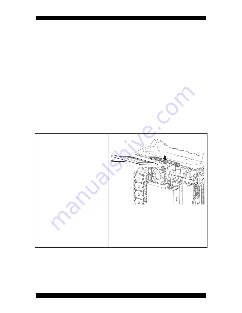
11) Slide the TRAY EXT (PL1.1.2) backward until its edge touches the machine. 

12) Release the stopper of the TRAY EXT 

MAIN by depressing the center section of 

the rear end of the GUIDE TRAY 

(PL1.1.24), and then remove the TRAY 

EXT MAIN. 

12)-1

12)-2


Содержание AcuLaser C2900N

Страница 1: ...Revision B Confidential Epson AcuLaser C2900N MiS00001SA Laser Printer Epson AcuLaser C2900N SEPG11001 SERVICE MANUAL ...

Страница 2: ...sponsibility for accidental or incidental damages resulting from technical or editorial errors or omissions in this manual the issue of this manual the execution of descriptions in this manual or the use of this manual This document is protected by copyright Do not photocopy or duplicate any part of this document in any form without written permission from SEIKO EPSON ...

Страница 3: ...erious injury may result If instructions are not observed injuries to workers or physical damage to assets including this laser printer may result Essentials for procedures steps rules and others Reference Incidental information to descriptions 3 Related documents Instruction manuals standard manuals Describe the operation and handling of this laser printer Performance specifications Describe in d...

Страница 4: ...lly always giving attention to safety 4 1 Power source Keep the power plug disconnected during the maintenance operation to prevent electric shock burns and other damages If the power supply should be kept connected to measure voltage or for other similar reasons take sufficient care to prevent electric shock by following the procedures in this manual While the printer is on never touch live parts...

Страница 5: ...e cover of the printer to confirm the operation of driving part 4 3 High temperature units When servicing high temperature units securing unit etc be sure to turn them off to prevent burns injuries and other troubles Remove the power plug and start service processes after they have cooled down sufficiently Because high temperature units are still hot after they complete an operation wait at least ...

Страница 6: ...ecified in this manual You should be well aware that the laser beams are capable of injuring you and other people near the printer Laser beams have features as follows Frequencies are smaller in width than other beams sun and electric bulbs and phases are uniform so that high monochromatic and convergence performance can be obtained and thin beams of light can reach places at a long distance Being...

Страница 7: ...onfidential 4 5 Warning caution labels Warning labels and caution labels are attached to this laser printer to prevent accidents Check those labels for peeling or stains when servicing the printer 4 5 1 Caution label for Printer MiS00004SA ...

Страница 8: ...ter is used on the repair and the maintenance work the use of the air duster products containing the inflammable gas is prohibited Make sure an antivirus software is installed on the computer used for service support Be sure to have the latest virus definition file for the software MiS00005SA ROS ASSY ...

Страница 9: ...i Revision B Epson AcuLaser C2900N Confidential 5 Unpacking the Printer Take extreme care to avoid personal injuries Check the printer for evidence of any damages Peel all tapes off the printer MiS00010GA ...

Страница 10: ...ial 6 Revision History Revision Date of Issue Description A May 20 2011 First release B July 7 2011 Revision up Chapter3 RRP8 3 PWBA ESS SFP PL8 1 5 revised the contents par tially RRP8 9 PWBA MCU PL8 2 13 revised the contents partially MiS00007SA ...

Страница 11: ...tion labels vi 4 5 1 Caution label for Printer vi 4 5 2 Caution label for ROS vii 5 Unpacking the Printer ix 6 Revision History ix Chapter 1 Troubleshooting 1 1 Chapter 2 Operation of Diagnostic 2 1 Chapter 3 Removal and Replacement Procedures 3 1 Chapter 4 Plug Jack P J Connector Locations 4 1 Chapter 5 Parts List 5 1 Chapter 6 Principles of Operation 6 1 Chapter 7 Wiring Diagrams and Signal Info...

Страница 12: ...Confidential CHAPTER 1 Troubleshooting ...

Страница 13: ... 1 4 1 5 Items To Be Confirmed Before Going To FIP Troubleshooting 1 6 2 FIP 1 12 2 1 FIP 1 12 2 2 Flow of FIP 1 12 2 3 Status Code List 1 13 3 Error Code FIP 1 25 4 Image Quality Trouble 1 126 4 1 Entry Chart for Image Quality Troubleshooting 1 126 4 2 Print Image Quality Specifications 1 130 4 3 Image Quality FIP 1 134 5 Abnormal Noise Trouble 1 173 5 1 Entry Chart for Abnormal Noise Troubleshoo...

Страница 14: ...re proceeding to the Fault Isolation Procedure FIP Operation of Diagnostic Chapter 2 Wiring Diagrams Chapter 7 and Principles of Operation Chapter 6 1 1 Flow of Troubleshooting Flow of the troubleshooting is as follows Check installation status Check trouble status Execute FIP Check for recovery End Replace the Printer Operation of Diagnostic Principles of Operation Wiring Diagrams Reference infor...

Страница 15: ...d at a place subjected to high low temperature humidity and sudden tem perature changes 5 The printer is not installed at or near water facilities humidifier heating appliance fire dust or in airflow from air conditioner 6 The printer is not installed in a place subjected to volatile or inflammable gas 7 The printer is not installed under direct sunlight 8 The printer is installed in a well ventil...

Страница 16: ...rinter powered ON be sure to remove the connector P J16 on the PWBA MCU unless otherwise required When checking some parts with the Front Cover removed and the printer powered ON be sure to remove the connector P J16 on the MCU Otherwise a high voltage may be output from the HVPS When connecting the connector P J16 on the MCU according to the instructions in the FIP never touch the HVPS and high v...

Страница 17: ...to 4PIN of P J3 7 P J1 P J2 in the FIP means measurement for all terminals corresponding between P J1 and P J2 based on Wiring Diagrams 8 In P J1 2PIN P J3 4PIN in the FIP where voltage is measured P J3 4PIN on the rear negative side is always at the AG analog ground SG signal ground or RTN return Therefore after checking of proper conductivity between AGs SGs or RTNs respectively the rear negativ...

Страница 18: ...body is called Tray 1 and the cassette below it is called Tray 2 15 Some of the instructions in the FIP are branched off depending on the specifications Follow the applicable instruction 16 For some optional components you may have to refer to the manual of the relevant component for troubleshooting Have the relevant manual at hand as needed ...

Страница 19: ...st Message appears on the operator panel When the test is completed Ready to Print is displayed 2 If menu settings changed from the operator panel have no effect check and try the actions below Settings in the software program the printer driver or the printer utilities are overriding the set tings made on the operator panel a Change the menu settings from the printer driver the printer utilities ...

Страница 20: ...he action below a Remove the stack of envelops from the Single Sheet Inserter SSI 5 If page breaks in unexpected places check and try the action below a Check the Job Time out in the Basic Settings menu and increase the value 6 If a job prints from the wrong source or on the wrong print media check and try the action below a Check the Paper Size and Paper Type in the Tray Settings menu on the prin...

Страница 21: ...ormance Grain Direction Grain refers to the alignment of the paper fibers in a sheet of paper Grain is either grain long running the length of the paper or grain short running the width of the paper For 60 g m2 to 135 g m2 16 lb to 36 lb bond paper grain long fibers are recommended For paper heavier than 135 g m2 36 lb bond grain short is preferred Fiber Content Most high quality xerographic paper...

Страница 22: ...ar in the text when printing on talc or acid paper Selecting Paper Proper paper selection helps prevent jams and ensures trouble free printing To help avoid jams or poor print quality Always use new undamaged paper Before loading the paper identify the recommended print side of the paper This information is usually indicated on the paper package Do not use paper that you have cut or trimmed Do not...

Страница 23: ... 8 5 x 14 inches Y Y Y Y Y Y Y Executive 7 25 x 10 5 inches Y Y Y Y Y Y N Envelope 10 4 125 x 9 5 inches Y N Y N N N N Monarch 3 875 x 7 5 inches Y 3 N Y N N N N DL 110 x 220 mm Y 3 N Y N N N N C5 162 x 229 mm Y N Y N N N N Custom Width 76 2 to 215 9 mm 3 to 8 5 inches Length 127 to 355 6 mm 5 to 14 inches Y Y N N N N N Custom Width 76 2 to 215 9 mm 3 to 8 5 inches 1 Length 127 to 355 6 mm 5 to 14...

Страница 24: ...2 Plain Thick 80 90 to 105 g m2 Recycled 60 to 105 g m2 Labels Inkjet printer paper cannot be used Covers 106 to 163 g m2 Covers Thick 164 to 216 g m2 Envelope Coated 106 to 163 g m2 Inkjet printer paper cannot be used Coated Thick 164 to 216 g m2 Inkjet printer paper cannot be used Letterhead Preprinted 64 g m2 Prepunched 64 g m2 Colored 64 g m2 ...

Страница 25: ...perator s operating method correct Turn off and turn on the Power Does error still occur when print is done by the problem mode When status code or LCD display is displayed When image quality trouble is occurred When abnormal noise is occurred Instruct how to operate End of work Refer to 2 3 Status Code List Refer to 3 Error Code FIP Refer to 4 1 Entry Chart for Image Quality Troubleshooting Refer...

Страница 26: ...397 Fuser Error Restart Printer Error 010 397 Restart Printer IOT Fuser Unit Failure The operation error of fuser unit Temperature anomaly error etc is detected FIP 1 4 421 Ready to Print Fuser Life Ready to Print Replace Soon IOT Fuser Unit Near Life The fuser unit is approaching the replacement time FIP 1 5 016 500 Erase Flash Err Restart Printer Error 016 500 Restart Printer Download Delete Err...

Страница 27: ... 742 Invalid ID Press Ok Button Error 016 742 Press Ok Button Download ID Error Download file ID is invalid FIP 1 10 743 Range Chk Error Press Ok Button Error 016 743 Press Ok Button Download Range Error At download write in destination address is invalid Range check error FIP 1 10 744 Check Sum Error Press Ok Button Error 016 744 Press Ok Button Download Check Sum Error Download file checksum is ...

Страница 28: ...e Optional Memory Module is installed 982 Disk Full Press Ok Button Error 016 982 Press Ok Button Disk Full The current printing job process cannot be continued because the RAM disk is full FIP 1 16 024 340 MCU Firmware Err Restart Printer Error 024 340 Restart Printer IOT Firmware Error MCU firmware error occurs FIP 1 17 360 Download Mode Send FW Data Error 024 360 Send FW Data MCU DownLoad Error...

Страница 29: ...tected FIP 1 25 326 Motor Error Restart Printer Error 042 326 Restart Printer IOT Sub Motor Failure Sub Motor failure is detected FIP 1 26 372 K Mode Sol Error Restart Printer Error 042 372 Restart Printer IOT K Mode Solenoid Error 1 The error is generated when K Mode Solenoid Color Mode Switching Solenoid does not operate in specified time FIP 1 27 373 K Mode Sol Error Restart Printer Error 042 3...

Страница 30: ... Printer Option Feeder Motor Failure Option Feeder Motor failure is detected FIP 1 34 900 Jam at Tray 1 or 2 Open Tray 1 or 2 Open Front Cover IOT Remain Option Feeder JAM The paper remains at the Paper Path Sensor of Tray 2 FIP 1 35 075 101 Jam at Front Cover Open Front Cover and Remove Paper IOT SSI Insert JAM SSI No Paper Sensor detect when a paper is inserted from SSI FIP 1 36 102 Chk Manual F...

Страница 31: ...ad edge does not reach the Regi Sensor when the sheet changes the direction in the Duplexer after the standby FIP 1 41 108 Jam at Duplexer Open Front Cover Lift Duplexer IOT Duplex JAM In the duplex printing mode the lead edge does not reach the SSI No Paper Sensor when the sheet changes the direction in the Duplexer after the standby FIP 1 41 215 Duplexer Error Restart Printer Error 077 215 Resta...

Страница 32: ...te K Full Waste Toner K Counter value has reached replacement time FIP 1 52 972 Insert Imaging Unit IOT PHD Detached The drum cartridge is not installed in the printer FIP 1 53 092 310 CTD Sensor Error Restart Printer Error 092 310 Restart Printer IOT CTD ACD Sensor Error CTD ACD sensor error analog to digital conversion etc is detected FIP 1 54 410 Ready to Print CTD Sensor CTD ADC Sensor Dustine...

Страница 33: ...ity of magenta FIP 1 58 921 Low Density Cyan Cartridge IOT C Toner Low Density Detects low density of cyan FIP 1 58 922 Low Density Black Cartridge IOT K Toner Low Density Detects low density of black FIP 1 58 925 Blk CRUM Error Restart Printer Error 093 925 Restart Printer IOT Black Toner CRUM Comm Fail The Black Toner Cartridge CRUM communication failure is detected FIP 1 59 926 Invalid Black IO...

Страница 34: ...s detected FIP 1 60 970 Insert Yellow Cartridge IOT Toner Cartridge Y Detached The Toner Cartridge Y is not installed in the printer If no toner cartridge has been installed in the printer a warning is indicated on the LCD panel in the following order 1 Black 2 Cyan 3 Magenta 4 Yellow FIP 1 62 971 Insert MagentaCartridge IOT Toner Cartridge M Detached The Toner Cartridge M is not installed in the ...

Страница 35: ...or Restart Printer Error 116 320 Restart Printer ESS DIMM Slot RAM Error Additional memory module is not completely inserted in the slot FIP 1 65 323 NV RAM Error Restart Printer Error 116 323 Restart Printer ESS NVRAM 1 R W Check Fail An error occurred during the master NVRAM 1 read write check at the time of initialization FIP 1 6 324 Controller Error Restart Printer Error 116 324 Restart Printe...

Страница 36: ...16 363 Restart Printer PCI Bus 1 Host Bridge Controller Error Connection error occurred between the PCI BUS port and the port of peripheral devices FIP 1 67 366 PCI Error Restart Printer Error 116 366 Restart Printer PCI Bus 1 Error Detected Connection error occurred between the PCI BUS port and the port of peripheral devices FIP 1 67 368 PCI Error Restart Printer Error 116 368 Restart Printer PCI...

Страница 37: ...y Module is installed 721 Collate Full Press Ok Button Error 116 721 Press Ok Button Collate Full Unable to collate due to insufficient memory FIP 1 68 193 700 Ready to Print Non GenuineToner Custom Toner Mode The printer is in custom toner mode FIP 1 69 Status Code Error Message Status Contents FIP to be referred LCD Flip ...

Страница 38: ...27 P J273 and P J419 connected surely Go to step 5 Reconnect the connector s P J27 P J273 and or P J419 surely then go to step 4 4 Does the error still occur when printing Go to step 5 End of work 5 Checking the HARN ASSY TRAY for continuity Disconnect P J419 from the PWBA FEED H Disconnect P J273 from the HARN ASSY OPTION Is each cable of P J419 P J273 continuous Go to step 6 Replace the HARN ASS...

Страница 39: ...he fuser unit has cooled down Check the connections between the PWBA MCU P J17 and fuser unit P J171 Check the connections between the fuser unit P J171 and PWBA LVPS P J47 Check the connections between the PWBA LVPS P J501 and P J502 and PWBA MCU P J14 and P J15 Are these connectors connected correctly Go to step 4 Reconnect the connector s P J17 P J47 P J171 P J501 P J502 P J14 and or P J15 corr...

Страница 40: ... J171 4pin J171 6pin J171 8pin J171 6pin J171 7pin Can the resistances be measured The resistances are 7 k ohm at 180 degrees C Go to step 6 Warning Start the operation after the fuser unit has cooled down Replace the fuser unit Refer to RRP6 1 After replacement be sure to clear the life counter value 6 Checking after the PWBA LVPS Replace the PWBA LVPS Refer to RRP8 5 Does the error still occur w...

Страница 41: ...6 1 After replacement be sure to clear the life counter value Go to step 2 2 Checking after resetting the fuser unit Reseat the fuser unit Warning Start the operation after the fuser unit has cooled down Does the error still occur when the power is turned OFF and ON Go to step 3 End of work 3 Checking after replacing the fuser unit Replace the fuser unit Refer to RRP6 1 Warning Start the operation...

Страница 42: ...ions between the PWBA MCU P J17 and fuser unit P J171 Check the connections between the fuser unit P J171 and PWBA LVPS P J47 Check the connections between the PWBA LVPS P J501 and P J502 and PWBA MCU P J14 and P J15 Are these connectors connected correctly Go to step 5 Reconnect the connector s P J17 P J47 P J171 P J501 P J502 P J14 and or P J15 correctly then go to step 4 4 Does the error still ...

Страница 43: ...er the fuser unit has cooled down Does the error still occur when the power is turned OFF and ON NOTE After replacement be sure to clear the life counter value Go to step 8 End of work 8 Checking after the PWBA LVPS Replace the PWBA LVPS Refer to RRP8 5 Does the error still occur when the power is turned off and on Replace the PWBA MCU Refer to RRP8 9 End of work Step Check Remedy Yes No ...

Страница 44: ...peration after the fuser unit has cooled down Go to step 3 Reseat the fuser unit then go step 2 2 Does the error still occur when the power is turned OFF and ON Go to step 3 End of work 3 Checking after replacing the fuser unit Replace the fuser unit Refer to RRP6 1 Warning Start the operation after the fuser unit has cooled down Does the error still occur when the power is turned OFF and ON NOTE ...

Страница 45: ...016 501 016 502 116 315 116 317 116 323 116 324 116 326 116 327 116 328 116 343 116 350 116 390 ESS Error Step Check Remedy Yes No Possible causative parts PWBA ESS SFP PL8 1 7 1 Does the error still occur when the power is turned OFF and ON Replace the PWBA ESS SFP Refer to RRP8 3 End of work ...

Страница 46: ...sible causative parts PWBA ESS SFP PL8 1 7 PWBA MCU PL8 2 13 1 Does the error still occur when the power is turned OFF and ON Go to step 2 End of work 2 Checking after replacing the PWBA ESS SFP Replace the PWBA ESS SFP Refer to RRP8 3 Does the error still occur when the power is turned off and on Replace the PWBA MCU Refer to RRP8 9 End of work ...

Страница 47: ...step 2 Install additional memory Or re install it properly 2 Checking after setting the Print Mode to Standard via the printer driver Set the Print Mode of the printer driver to Standard Does the error persist during printing Go to step 3 End of work 3 Deleting the data by executing Clear Storage Execute Clear Storage under Maintenance in the Control Panel Does the error persist during printing Th...

Страница 48: ...BA ESS SFP PL8 1 7 1 Checking cable plug unplug Plug and unplug the cable USB cable or I F cable Does the error still occur when printing Go to step 2 End of work 2 Checking after replacing the Cable Replace the cable USB cable or I F cable Does the error still occur when the power is turned off and on Replace the PWBA ESS SFP Refer to RRP8 3 End of work ...

Страница 49: ...correct file 2 Checking the connection between PC and printer Are your PC and the printer correctly connected by USB or LAN Disconnect and reconnect the USB or network cable Does the error still occur when the power is turned OFF and ON Go to step 3 End of work 3 Checking after reseating the PWBA ESS SFP Reseat the PWBA ESS SFP Does the error still occur when the power is turned OFF and ON Go to s...

Страница 50: ... 753 016 755 PDF password error PDF print disabled error Step Check Remedy Yes No Possible causative parts 1 Checking the PDF data Enter the correct PDF document password again Change the PDF document security setting Does the error still occur when printing End of work Upgrade the firmware ...

Страница 51: ...onfidential FIP 1 12 016 757 Auditron Invalid User Step Check Remedy Yes No Possible causative parts 1 Checking the user s account setting Set the correct user s account user name and password Does the error still occur when printing End of work Upgrade the firmware ...

Страница 52: ...vision B Confidential FIP 1 13 016 758 Auditron Disabled Function Step Check Remedy Yes No Possible causative parts 1 Checking the Black White setting Set the Color Mode to the Color Does the error still occur when printing End of work Upgrade the firmware ...

Страница 53: ...dential FIP 1 14 016 759 Auditron Reached Limit Step Check Remedy Yes No Possible causative parts 1 Checking the Color Track setting Set the correct value of User Registration exceed the limitation Does the error still occur when printing End of work Upgrade the firmware ...

Страница 54: ...tep 2 2 Does the error still occur when printing Go to step 3 End of work 3 Checking the paper size setup Does the using paper size match the printer setup value Go to step 5 Go to step 4 4 Setup the paper size through your PC Does the error still occur when printing Go to step 5 End of work 5 Checking the printing job Does the error still occur when printing the Windows test print Go to step 6 En...

Страница 55: ...int Print the small size file like a Windows test page Does the error still occur when printing Go to step 3 Add the MEMORY CARD or divide the printing job 3 Is the customer using the recommended memory card Go to step 4 Replace to the recommended memory card 4 Checking the MEMORY CARD OPTION installation Reseat the MEMORY CARD OPTION Does the error still occur when turning on the power Go to step...

Страница 56: ...ill occur after several ON OFF procedures of the power Go to step 2 End of work 1 2 Checking the firmware version Is the firmware the latest version Go to step 3 Upgrade the firmware then go to step 3 3 Checking after resetting the PWBA MCU Reseat the PWBA MCU Does the error still occur when the power is turned OFF and ON Go to step 4 End of work 1 4 Checking after replacing the PWBA MCU Replace t...

Страница 57: ...heck Remedy Yes No Possible causative parts PWBA MCU PL8 2 13 1 Download the Firmware using the download mode Refer to 1 2 Firmware version up procedure using the download mode of Appendix_1 Firmware download Does the error still occur when the power is turned off and on Replace the PWBA MCU Refer to RRP8 9 End of work ...

Страница 58: ...king Time out Step Check Remedy Yes No Possible causative parts PWBA ESS SFP PL8 1 7 1 Checking the firmware version Is the firmware the latest version Go to step 2 Upgrade the firmware then go step 2 2 Checking the error Does the error still occur when printing Replace the PWBA ESS SFP Refer to RRP8 3 End of work ...

Страница 59: ...P Are P J10 and P J101 connected correctly Go to step 4 Reconnect the connector s P J10 and or P J101 correctly then go to step 3 3 Does the error still occur when the power is turned OFF and ON Go to step 4 End of work 4 Checking the HARNESS ASSY ESS MG SFP for continuity Disconnect J10 from the PWBA MCU Disconnect J101 from the PWBA ESS SFP Is each cable of J10 J101 continuous Go to step 5 Repla...

Страница 60: ... 21 024 985 Waiting for Continue key to be pressed after reloading paper to the SSI Step Check Remedy Yes No Possible causative parts PWBA ESS SFP PL8 1 7 1 Checking the firmware version Is the firmware the latest version Replace the PWBA ESS SFP Refer to RRP8 3 Upgrade the firmware ...

Страница 61: ...dential FIP 1 22 027 446 027 452 IPv6 duplicate IPv4 duplicate Step Check Remedy Yes No Possible causative parts 1 Checking the IP addresses Remove the duplicate IP addresses Does the error still occur when the power is turned off and on End of work Upgrade the firmware ...

Страница 62: ...ccur when the power is turned OFF and ON Go to step 3 End of work 1 3 Checking after resetting the PWBA MCU Reseat the PWBA MCU Does the error still occur when the power is turned OFF and ON Go to step 4 End of work 1 4 Checking the connectors for connection Check the connections between the PWBA EEPROM and PWBA MCU Are P J 144 and P J 42 connected surely Go to step 6 Reconnect the connector s P J...

Страница 63: ...to step 3 3 Check the connection between the FAN and the PWBA LVPS Is P J503 on the PWBA LVPS connected correctly Go to step 5 Reconnect the connector P J 503 correctly then go to step 4 4 Does the error still occur when the power is turned OFF and ON Go to step 5 End of work 5 Check the connections between the PWBA LVPS and PWBA MCU Are P J501 and P J14 connected correctly Go to step 7 Reconnect ...

Страница 64: ...s P503 1pin ground on the PWBA LVPS about 24 VDC when the interlock switch HARN ASSY INTERLOCK is pushed Replace the FAN Refer to RRP8 1 Go to step 9 9 Checking after replacing the PWBA LVPS Replace the PWBA LVPS Refer to RRP8 5 Does the error still occur when the power is turned OFF and ON Replace the PWBA MCU Refer to RRP8 9 End of work Step Check Remedy Yes No ...

Страница 65: ...nectors of the MAIN MOTOR for connection Check the connections between the PWBA MCU and DRIVE ASSY MAIN Are P J21 and P J211 connected correctly Go to step 6 Reconnect the connector s P J21 and or P J211 correctly then go to step 5 5 Does the error still occur when the power is turned OFF and ON Go to step 6 End of work 6 Checking the HARNESS ASSY MAIN MOT MG SFP for continuity Disconnect J21 from...

Страница 66: ... MCU Refer to RRP8 9 Go to step 4 4 Checking the connectors of the SUB MOTOR for connection Check the connections between the PWBA MCU and DRIVE ASSY SUB Are P J22 and P J221 connected correctly Go to step 6 Reconnect the connector s P J22 and or P J221 correctly then go to step 5 5 Does the error still occur when the power is turned OFF and ON Go to step 6 End of work 6 Checking the HARNESS ASSY ...

Страница 67: ... the DRIVE ASSY PH Reseat the DRIVE ASSY PH Does the error still occur when the power is turned OFF and ON Go to step 8 End of work 4 Checking the connector of the K Mode Solenoid in the DRIVE ASSY PH for connection Check the connection between the PWBA MCU and K Mode Solenoid Is P J24 connected correctly Go to step 6 Reconnect the connector P J24 correctly then go to step 5 5 Does the error still...

Страница 68: ...1 from the K Mode Sensor Is each cable of J26 J261 continuous Go to step 11 Replace the HARN ASSY KSNR REGCL 11 Checking the power to the K Mode Sensor Disconnect J26 from the PWBA MCU Is the voltage across P26 1pin ground on the PWBA MCU about 3 3 VDC Go to step 12 Replace the PWBA MCU Refer to RRP8 9 12 Checking the K Mode Sensor for operation Remove the DRIVE ASSY PH from the printer once but P...

Страница 69: ...Reconnect the connector s P J20 and or P J201 surely then go to step 2 2 Does the error still occur when the power is turned off and on Go to step 3 End of work 3 Checking the HARN ASSY HUM for continuity Disconnect P J20 from the PWBA MCU Disconnect P J201 from the SENSOR HUM Is each cable of P J20 P J201 continuous Go to step 4 Replace the HARN ASSY HUM 4 Checking the output power of SENSOR HUM ...

Страница 70: ...between the ROS ASSY and PWBA MCU Are P J40 P J41 P J411 and P J412 connected correctly Go to step 6 Reconnect the connector s P J40 P J41 P J411 and or P J412 correctly then go to step 5 5 Does the error still occur when the power is turned OFF and ON Go to step 6 End of work 6 Checking the HARN ASSY ROS RE for continuity Disconnect P J40 from the PWBA MCU Disconnect P J411 from the ROS ASSY Is e...

Страница 71: ...y Does the error still occur when printing Go to step 5 End of work 5 Checking the Main Motor DRIVE ASSY MAIN for operation Does the Main Motor DRIVE ASSY MAIN operate properly Checked by Digital Output Main Motor in IOT Diag of diagnosis During this check close the COVER ASSY FRONT MG Go to step 6 Go to step 19 6 Checking the DRIVE ASSY PH for operation Does the ROLL ASSY FEED ROLL ASSY REGI and ...

Страница 72: ...tep 14 14 Checking the ACTUATOR REGI IN for shape and operation Remove the CHUTE ASSY LOW PL3 2 27 once to check the shape and operation Are the shape and operation of the ACTUATOR REGI IN normal Go to step 15 Reseat the ACTUATOR REGI IN If broken or deformed replace it 15 Checking the Regi Sensor SENSOR PHOTO for operation Does the number on the screen increase by one when the actuator ACTUATOR R...

Страница 73: ...U Disconnect J211 from the DRIVE ASSY MAIN Is each cable of J21 J211 continuous Go to step 21 Replace the HARNESS ASSY MAIN MOT MG SFP 21 Checking the power to the DRIVE ASSY MAIN Disconnect J21 from the PWBA MCU Are the voltages across J21 2pin J21 4pin ground on the PWBA MCU about 24 VDC when the interlock switch HARN ASSY INTERLOCK is pushed Replace the DRIVE ASSY MAIN Refer to RRP7 2 Replace t...

Страница 74: ...PWBA MCU and SENSOR PHOTO Are P J23 and P J232 connected correctly Go to step 27 Reconnect the connector s P J23 and or P J232 correctly 27 Checking the HARN ASSY L SIDE for continuity Disconnect J23 from the PWBA MCU Disconnect J232 from the SENSOR PHOTO Is each cable of J23 J232 continuous Go to step 28 Replace the HARN ASSY L SIDE 28 Checking the power to the SENSOR PHOTO Disconnect J23 from th...

Страница 75: ... P262 from the CLUTCH ASSY DRV Is each cable of J26 P262 continuous Go to step 32 Replace the HARN ASSY KSNR REGCL 32 Checking the power to the CLUTCH ASSY DRV Disconnect J26 from the PWBA MCU Is the voltage across P26 4pin ground on the PWBA MCU about 24 VDC when the Interlock Switch HARN ASSY INTERLOCK is pushed Go to step 33 Replace the PWBA MCU Refer to RRP8 9 33 Checking the CLUTCH ASSY DRV f...

Страница 76: ...then latch correctly Does the error still occur when printing Go to step 5 End of work 5 Checking the Paper Path Sensor SENSOR PHOTO for operation Does the number on the screen increase by one when the actuator ACTUATOR REGI IN is operated Checked by Digital Input OptionPathSensor in IOT Diag of diagnosis Go to step 6 Go to step 15 6 Checking the MOTOR ASSY SUB for operation Does the MOTOR ASSY SU...

Страница 77: ...es or stains from the paper transfer path Replace the FEEDER ASSY OPT Refer to RRP10 1 15 Checking the connectors of the SENSOR PHOTO Paper Path Sensor for connection Check the connections between the PWBA FFE D and SENSOR PHOTO Are P J420 and P J4200 connected correctly Go to step 16 Reconnect the connector s P J420 and or P J4200 correctly 16 Checking the HARNESS ASSY TRAY COMP for continuity Di...

Страница 78: ... Go to step 25 Replace the PWBA FEED H 25 Checking the SOLENOID FEED MSI for resistance Disconnect P J4211 of the SOLENOID FEED MSI Is the resistance across J4211 1 and J4211 2 approximately 96 ohm Replace the PWBA FEED H Replace the SOLENOID FEED MSI 26 Checking the connectors of the Feed Clutch CLUTCH ASSY DRV for connection Check the connections between the PWBA FEDD H and Feed Clutch Are P J42...

Страница 79: ...Checking the COVER ASSY FRONT MG for latching Open and close the COVER ASSY FRONT MG and then latch correctly Does the error still occur when printing Go to step 5 End of work 5 Checking the Main Motor DRIVE ASSY MAIN for operation Does the Main Motor DRIVE ASSY MAIN operate properly Checked by Digital Output Main Motor in IOT Diag of diagnosis During this check cheat the interlock switch HARN ASS...

Страница 80: ...he paper lead edge stay after the ROLL ASSY REGI and ROLL REGI METAL then go to step 16 13 Checking the paper transfer path between the ROLL ASSY FEED and ROLL ASSY REGI Are there any obstacles on the paper transfer path Remove the obstacles or stains from the paper transfer path Go to step 14 14 Checking the ACTUATOR REGI IN for shape and operation Remove the CHUTE ASSY LOW PL3 2 27 once to check...

Страница 81: ... the PWBA MCU and DRIVE ASSY MAIN Main Motor Are P J21 and P J211 connected correctly Go to step 20 Reconnect the connector s P J21 and or P J211 correctly 20 Checking the HARNESS ASSY MAIN MOT MG SFP for continuity Disconnect J21 from the PWBA MCU Disconnect J211 from the DRIVE ASSY MAIN Is each cable of J21 J211 continuous Go to step 21 Replace the HARNESS ASSY MAIN MOT MG SFP 21 Checking the po...

Страница 82: ...cking the connectors of the SENSOR PHOTO Regi Sensor for connection Check the connections between the PWBA MCU and SENSOR PHOTO Are P J23 and P J232 connected correctly Go to step 27 Reconnect the connector s P J23 and or P J232 correctly 27 Checking the HARN ASSY L SIDE for continuity Disconnect J23 from the PWBA MCU Disconnect J232 from the SENSOR PHOTO Is each cable of J23 J232 continuous Go to...

Страница 83: ... P262 from the CLUTCH ASSY DRV Is each cable of J26 P262 continuous Go to step 32 Replace the HARN ASSY KSNR REGCL 32 Checking the power to the CLUTCH ASSY DRV Disconnect J26 from the PWBA MCU Is the voltage across P26 4pin ground on the PWBA MCU about 24 VDC when the Interlock Switch HARN ASSY INTERLOCK is pushed Go to step 33 Replace the PWBA MCU Refer to RRP8 9 33 Checking the CLUTCH ASSY DRV f...

Страница 84: ... P J419 connected surely Go to step 5 Reconnect the connector s P J27 P J273 and or P J419 surely then go to step 4 4 Does the error still occur when the power is turned OFF and ON Go to step 5 End of work 5 Checking the HARNESS ASSY TRAY for continuity Disconnect P J419 from the PWBA FEED H Disconnect P J273 from the HARN ASSY OPTION Is each cable of P J419 P J273 continuous Go to step 6 Replace ...

Страница 85: ... PWBA FEED H and MOTOR ASSY SUB Are P J422 and P J4221 connected correctly Go to step 4 Reconnect the connector s P J422 and or P J4221 correctly then go to step 3 3 Does the error still occur when the power is turned OFF and ON Go to step 4 End of work 4 Checking the HARNESS ASSY TRAY MOT for continuity Disconnect J422 from the PWBA FEED H Disconnect J4221 from the MOTOR ASSY SUB Is each cable of...

Страница 86: ... MCU Refer to RRP8 9 Go to step 2 2 Checking the connectors for connection Check the connections between the PWBA FEED H and Paper Path Sensor Are P J420 and P J4200 connected correctly Go to step 3 Reconnect the connector s P J420 and or P J4200 correctly 3 Checking the HARNESS ASSY TRAY COMP for continuity Disconnect J420 from the PWBA FEED H Disconnect J4200 from the Paper Path Sensor Is each c...

Страница 87: ... Checking the connectors of the SENSOR PHOTO SSI No Paper Sensor for connection Check the connections between the PWBA MCU and SENSOR PHOTO Are P J23 and P J233 connected correctly Go to step 6 Reconnect the connector s P J23 and or P J233 correctly then go to step 5 5 Does the error still occur when printing Go to step 6 End of work 6 Checking the HARN ASSY L SIDE for continuity Disconnect J23 fr...

Страница 88: ... Digital Output Regi Clutch in IOT Diag of diagnosis Go to step 4 Replace the printer 4 Checking the Regi Sensor for operation Does the number on the screen increase by one when the actuator ACTUATOR REGI IN is operated Checked by Digital Input Regi Sensor on IOT Diag of diagnosis Replace the PWBA MCU Refer to RRP8 9 Go to step 5 5 Checking the ACTUATOR REGI IN for shape and operation Remove the C...

Страница 89: ...SENSOR PHOTO Disconnect J23 from the PWBA MCU Is the voltage across P23 3pin ground on the PWBA MCU about 3 3 VDC Go to step 9 Replace the PWBA MCU Refer to RRP8 9 9 Checking the SENSOR PHOTO for operation Check the voltage across J23 5pin ground on the PWBA MCU Remove the CHUTE LOW CST PL3 2 35 once to check the operation Does the voltage change when the actuator ACTUATOR REGI IN is operated Repl...

Страница 90: ...k 4 Checking the COVER ASSY FRONT MG for latching Open and close the COVER ASSY FRONT MG and then latch correctly Does the error still occur when printing Go to step 5 End of work 5 Checking the Main Motor DRIVE ASSY MAIN for operation Does the Main Motor DRIVE ASSY MAIN operate properly Checked by Digital Output Main Motor on IOT Diag of diagnosis During this check cheat the interlock switch HARN...

Страница 91: ...er the ROLL ASSY REGI and ROLL REGI METAL then go to step 16 13 Checking the paper transfer path between the ROLL ASSY FEED and ROLL ASSY REGI Are there any obstacles on the paper transfer path Remove the obstacles or stains from the paper transfer path Go to step 14 14 Checking the ACTUATOR REGI IN for shape and operation Remove the CHUTE ASSY LOW PL3 2 27 once to check the shape and operation Ar...

Страница 92: ...OT MG SFP 20 Checking the power to the DRIVE ASSY MAIN Disconnect J21 from the PWBA MCU Are the voltages across J21 2pin J21 4pin ground on the PWBA MCU about 24 VDC when the interlock switch HARN ASSY INTERLOCK is pushed Replace the DRIVE ASSY MAIN Refer to RRP7 2 Replace the PWBA MCU Refer to RRP8 9 21 Checking the connectors of the SOLENOID FEED Cassette Feed Solenoid for connection Check the c...

Страница 93: ...ectly 26 Checking the HARN ASSY L SIDE for continuity Disconnect J23 from the PWBA MCU Disconnect J232 from the SENSOR PHOTO Is each cable of J23 J232 continuous Go to step 27 Replace the HARN ASSY L SIDE 27 Checking the power to the SENSOR PHOTO Disconnect J23 from the PWBA MCU Is the voltage across P23 3pin ground on the PWBA MCU about 3 3 VDC Go to step 28 Replace the PWBA MCU Refer to RRP8 9 2...

Страница 94: ...printing Go to step 4 End of work 4 Checking the COVER ASSY FRONT MG for latching Open and close the COVER ASSY FRONT MG and then latch correctly Does the error still occur when printing Go to step 5 End of work 5 Checking the Main Motor DRIVE ASSY MAIN for operation Does the Main Motor DRIVE ASSY MAIN operate properly Checked by Digital Output Main Motor on IOT Diag of diagnosis During this check...

Страница 95: ...er the ROLL ASSY REGI and ROLL REGI METAL then go to step 16 13 Checking the paper transfer path between the ROLL ASSY FEED and ROLL ASSY REGI Are there any obstacles on the paper transfer path Remove the obstacles or stains from the paper transfer path Go to step 14 14 Checking the ACTUATOR REGI IN for shape and operation Remove the CHUTE ASSY LOW PL3 2 27 once to check the shape and operation Ar...

Страница 96: ...OT MG SFP 20 Checking the power to the DRIVE ASSY MAIN Disconnect J21 from the PWBA MCU Are the voltages across J21 2pin J21 4pin ground on the PWBA MCU about 24 VDC when the interlock switch HARN ASSY INTERLOCK is pushed Replace the DRIVE ASSY MAIN Refer to RRP7 2 Replace the PWBA MCU Refer to RRP8 9 21 Checking the connectors of the SOLENOID FEED Cassette Feed Solenoid for connection Check the c...

Страница 97: ...ectly 26 Checking the HARN ASSY L SIDE for continuity Disconnect J23 from the PWBA MCU Disconnect J232 from the SENSOR PHOTO Is each cable of J23 J232 continuous Go to step 27 Replace the HARN ASSY L SIDE 27 Checking the power to the SENSOR PHOTO Disconnect J23 from the PWBA MCU Is the voltage across P23 3pin ground on the PWBA MCU about 3 3 VDC Go to step 28 Replace the PWBA MCU Refer to RRP8 9 2...

Страница 98: ...e connector s P J17 and or P J171 correctly 4 Checking the HARNESS ASSY FUSING UNIT MG SFP for continuity Remove the fuser unit Disconnect J17 from the PWBA MCU Is each cable of J17 P171 continuous NOTE P171 is attached to the frame Go to step 5 Replace the HARNESS ASSY FUSING UNIT MG SFP 5 Checking the power to the Exit Sensor in the fuser unit Disconnect the connector of J17 on the PWBA MCU Is t...

Страница 99: ...AcuLaser C2900N Revision B Confidential 8 Checking the Regi Clutch Does the clutch noise occur Checked by Digital Output Regi Clutch in IOT Diag of diagnosis Replace the printer Replace the PWBA MCU Refer to RRP8 9 Step Check Remedy Yes No ...

Страница 100: ...hen printing Go to step 4 End of work 4 Checking the DRIVE ASSY EXIT for operation Does the DRIVE ASSY EXIT operate properly Checked by Digital Output Exit Motor on IOT Diag of diagnosis During this check cheat the interlock switch HARN ASSY INTERLOCK Go to step 5 Replace FEEDER ASSY DUP SFP STD Refer to RRP9 1 5 Checking the DRIVE ASSY DUP for operation Does the DRIVE ASSY DUP operate properly Ch...

Страница 101: ...e PWBA MCU Disconnect J232 from the SENSOR PHOTO Is each cable of J23 J232 continuous Go to step 12 Replace the HARN ASSY L SIDE 12 Checking the power to the SENSOR PHOTO Disconnect J23 from the PWBA MCU Is the voltage across P23 3pin ground on the PWBA MCU about 3 3 VDC Go to step 13 Replace the PWBA MCU Refer to RRP8 9 13 Checking the SENSOR PHOTO for operation Check the voltage across 23 5pin g...

Страница 102: ...go to step 4 4 Does the error still occur when the power is turned OFF and ON Go to step 5 End of work 5 Checking the HARNESS ASSY DUP for continuity Disconnect P J601 from the PWBA DUP Disconnect P J272 from the HARNE ASSY DUP Is each cable of P J601 P J272 continuous Go to step 6 Replace the HARNESS ASSY DUP 6 Checking the HARN ASSY DUP RELAY for continuity Disconnect P J271 from the HARNESS ASS...

Страница 103: ...e COVER ASSY FRONT MG Refer to RRP1 8 3 Checking the interlock switch for operation Does the number on the screen increase by one when the COVER ASSY FRONT MG is closed and opened Checked by Digital Input Cover Open Sensor in IOT Diag of diagnosis Replace the PWBA MCU Refer to RRP8 9 Go to step 4 4 Checking the connectors for connection Check the connections between PWBA MCU and PWBA LVPS Are P J1...

Страница 104: ...ge across P44 1 ground on the PWBA LVPS about 24 VDC Go to step 8 Replace the PWBA LVPS Refer to RRP8 5 8 Checking the Interlock Switch for operation Check the voltage across P44 3pin ground on the PWBA LVPS Does the voltage change when the Interlock Switch is turned ON OFF Replace the PWBA LVPS Refer to RRP8 5 Replace the HARN ASSY INTERLOCK Refer to RRP8 6 Step Check Remedy Yes No ...

Страница 105: ...correctly Go to step 3 Reseat or replace the COVER ASSY WINDOW TNR Refer to RRP1 6 3 Checking the Side R Switch SWITCH for operation Does the number on the screen increase by one when the COVER ASSY WINDOW TRN is closed and opened Checked by Digital Input Side Switch in IOT Diag of diagnosis Replace the PWBA MCU Refer to RRP8 9 Go to step 4 4 Checking the HARN ASSY SIDE SW for continuity Disconnec...

Страница 106: ... error still occur when printing Go to step 7 End of work 7 Checking the COVER ASSY FRONT MG for latching Open and close the COVER ASSY FRONT MG and then latch correctly Does the error still occur when printing Go to step 8 End of work 8 Checking the fuser unit Are there any remaining paper and or foreign substance in the fuser unit Warning Start the operation after the fuser unit has cooled down ...

Страница 107: ...ached to the frame Go to step 13 Replace the HARNESS ASSY FUSING UNIT MG SFP 13 Checking the power to the Exit Sensor in the fuser unit Disconnect the connector of J17 on the PWBA MCU Is the voltage across J17 1pin ground on the PWBA MCU about 3 3 VDC Go to step 14 Replace the PWBA MCU Refer to RRP8 9 14 Checking the Exit Sensor for operation Check the voltage across J17 3pin ground on the PWBA MC...

Страница 108: ...cking after reloading a new paper Reload a new paper Does the error still occur when printing Go to step 6 End of work 6 Checking the COVER ASSY FRONT MG for latching Open and close the COVER ASSY FRONT MG and then latch correctly Does the error still occur when printing Go to step 7 End of work 7 Checking around the Regi Sensor Are there any remaining paper and or foreign substance around the Reg...

Страница 109: ...the CHUTE ASSY LOW PL3 2 27 once to check the operation Checked by Digital Input Regi Sensor in IOT Diag of diagnosis Go to step 13 Go to step 16 13 Checking the Regi Clutch CLUTCH ASSY DRV for operation and ROLL ASSY REGI and ROLL REGI METAL for rotation Checked by Digital Output Regi Clutch in IOT Diag of diagnosis Does the Regi Clutch CLUTCH ASSY DRV operate properly and the ROLL ASSY REGI and ...

Страница 110: ...he HARN ASSY L SIDE for continuity Disconnect J23 from the PWBA MCU Disconnect J232 from the SENSOR PHOTO Is each cable of J23 J232 continuous Go to step 18 Replace the HARN ASSY L SIDE 18 Checking the power to the SENSOR PHOTO Disconnect J23 from the PWBA MCU Is the voltage across P23 3pin ground on the PWBA MCU about 3 3 VDC Go to step 19 Replace the PWBA MCU Refer to RRP8 9 19 Checking the SENS...

Страница 111: ...23 Checking the CLUTCH ASSY DRV for resistance Disconnect P J262 of the CLUTCH ASSY DRV Is the resistance across J262 1 and J262 2 approximately 280 ohm Replace the PWBA MCU Refer to RRP8 9 Replace the CLUTCH ASSY DRV Refer to RRP3 1 24 Checking the connectors for connection Check the connections between the PWBA MCU and DRIVE ASSY MAIN Main Motor Are P J21 and P J211 connected correctly Go to ste...

Страница 112: ...on Check the connections between the PWBA MCU and SENSOR PHOTO Are P J23 and P J233 connected correctly Go to step 3 Reconnect the connector s P J23 and or P J233 correctly 3 Checking the connectors of the SENSOR PHOTO SSI No Paper Sensor for connection Check the connections between the PWBA MCU and SENSOR PHOTO Are P J23 and P J233 connected correctly Go to step 4 Reconnect the connector s P J23 ...

Страница 113: ... end Replace the DRUM CARTRIDGE Refer to RRP4 6 Go to step 2 2 Checking after resetting the DRUM CARTRIDGE Reseat the DRUM CARTRIDGE Does the error still occur when the power is turned OFF and ON Go to step 3 End of work 3 Checking after replacing the DRUM CARTRIDGE Replace the DRUM CARTRIDGE Refer to RRP4 6 CAUTION Be sure to pull eight sealing tapes out from a new DRUM CARTRIDGE before installat...

Страница 114: ... sealing tapes total eight sealing tapes been pulled out After checking reseat the DRUM CARTRIDGE correctly Go to step 3 Pull the sealing tapes out then go to step 2 2 Does the error still occur when the power is turned OFF and ON Go to step 3 End of work 3 Checking after replacing the DRUM CARTRIDGE Replace the DRUM CARTRIDGE Refer to RRP4 6 CAUTION Be sure to pull eight sealing tapes out from a ...

Страница 115: ...ARTRIDGE Does the error still occur when the power is turned OFF and ON Go to step 5 End of work 5 Checking the connectors for connection Check the connectors between the PWBA MCU and DRUM CARTRIDGE Are P J42 and P J422 connected correctly Go to step 7 Reconnect the connector s P J42 and or P J422 surly then go to step 6 6 Does the error still occur when the power is turned OFF and ON Go to step 7...

Страница 116: ...d Replace the DRUM CARTRIDGE Refer to RRP4 6 Go to step 2 2 Checking after resetting the DRUM CARTRIDGE Reseat the DRUM CARTRIDGE Does the error still occur when the power is turned OFF and ON Go to step 3 End of work 3 Checking after replacing the DRUM CARTRIDGE Replace the DRUM CARTRIDGE Refer to RRP4 6 CAUTION Be sure to pull eight sealing tapes out from a new DRUM CARTRIDGE before installation...

Страница 117: ...sible causative parts TONER CARTRIDGE Y PL5 1 24 TONER CARTRIDGE M PL5 1 23 TONER CARTRIDGE C PL5 1 22 TONER CARTRIDGE K PL5 1 21 PWBA MCU PL8 2 13 1 Checking after replacing the TONER CARTRIDGE Y M C or K Replace the TONER CARTRIDGE Y M C or K Refer to RRP5 4 Does the error still occur when the power is turned OFF and ON Replace the PWBA MCU Refer to RRP8 9 End of work ...

Страница 118: ...2 and P J422 connected correctly Go to step 4 Reconnect the connector s P J42 and or P J422 surly then go to step 3 3 Does the error still occur when the power is turned OFF and ON Go to step 4 End of work 4 Checking the HARN ASSY PHD XPRO for continuity Disconnect P422 from the DRUM CARTRIDGE Disconnect J42 from the PWBA MCU Is each cable of P422 J42 continuous Go to step 5 Replace the HARN ASSY ...

Страница 119: ...sheet on the DRUM CARTRIDGE Remove the protection sheet Go to step 2 2 Checking the CTD ADC Sensor Window Open the COVER ASSY FRONT MG Is the CTD ADC Sensor window dirty Go to step 3 Go to step 4 3 Turn off the power and gently wipe the CTD ADC Sensor window with a clean dry cloth or cotton swab After wiping the window close the COVER ASSY FRONT MG Does the error still occur when the power is turn...

Страница 120: ...and P J181 Y P J182 M connected correctly Are P J19 and P J191 C P J192 K connected correctly Example For Yellow Go to step 9 Reconnect the connector s P J18 and P J181 surly then go to step 8 or reconnect the connector s P J19 and P J191 surly then go to step 8 8 Does the error still occur when the power is turned OFF and ON Go to step 9 End of work 9 Checking the HARN ASSY TNR MOT for continuity...

Страница 121: ...check that the lock key is in the lock position Refer to RRP5 4 Does the error still occur when the power is turned OFF and ON Go to step 13 End of work 13 Checking after replacing the DRUM CARTRIDGE Replace the DRUM CARTRIDGE Refer to RRP4 6 Does the error still occur when the power is turned OFF and ON Go to step 14 End of work 14 Checking after resetting the TRANSFER ASSY Reseat the TRANSFER AS...

Страница 122: ...ected correctly Go to step 4 Reconnect the connector s P J28 and or P J281 correctly then go to step 3 3 Does the error still occur when the power is turned OFF and ON Go to step 4 End of work 4 Checking the HARN ASSY L SIDE for continuity Disconnect J28 from the PWBA MCU Disconnect J281 from the TRANSFER ASSY Is each cable of J28 J281 continuous Go to step 5 Replace the HARN ASSY L SIDE 5 Checkin...

Страница 123: ...tting the SENSOR HUM Reseat the SENSOR HUM Does the error still occur when the power is turned OFF and ON Go to step 3 End of work 3 Checking the HARN ASSY HUM for continuity Disconnect J20 from the PWBA MCU Disconnect J201 from the SENSOR HUM Is each cable of J20 J201 continuous Go to step 4 Replace the HARN ASSY HUM 4 Checking the power to SENSOR HUM Disconnect the connector of J20 from the PWBA...

Страница 124: ...ssible causative parts TONER CARTRIDGE Y PL5 1 24 TONER CARTRIDGE M PL5 1 23 TONER CARTRIDGE C PL5 1 22 TONER CARTRIDGE K PL5 1 21 PWBA MCU PL8 2 13 1 Checking after replacing the TONER CARTRIDGE Y M C or K Replace the TONER CARTRIDGE Y M C or K Refer to RRP5 4 Does the error still occur when the power is turned OFF and ON Replace the PWBA MCU Refer to RRP8 9 End of work ...

Страница 125: ...heck the life count value of the TONER CARTRIDGE Y M C or K in Parameter in IOT Diag of diagnosis Does the remainder value shows the near of the end Refer to Chapter 2 for details of the life counter value Replace the TONER CARTRIDGE Y M C or K then go to step 4 Refer to RRP5 4 Go to step 7 4 Does the error still occur when the power is turned OFF and ON Go to step 7 End of work 5 Checking the ton...

Страница 126: ... Motor in IOT Diag of diagnosis During this check cheat the interlock switch HARN ASSY INTERLOCK Go to step 11 Go to step 12 11 Checking the gears of the DISPENSER ASSY for shape and operation Are the shape and operation of the gears of the DISPENSER ASSY normal Example For Yellow Go to step 16 Replace the defective gear s or DISPENSER ASSY Refer to RRP5 1 12 Checking the connector for connection ...

Страница 127: ...OCK is pushed Replace the MOTOR ASSY DISP or FRAME ASSY MOT Refer to RRP5 1 Replace the PWBA MCU Refer to RRP8 9 16 Checking after replacing the TONER CARTRIDGE Y M C or K Replace the TONER CARTRIDGE Y M C or K and check that the lock key is in the lock position Refer to RRP5 4 Does the error still occur when the power is turned OFF and ON Go to step 17 End of work 17 Checking after replacing the ...

Страница 128: ... J312 M P J313 C P J314 K connected surely Go to step 4 Reconnect the connector s surely then go to step 3 3 Does the error still occur when the power is turned off and on Go to step 4 End of work 4 Checking the HARN ASSY TONER CRUM for continuity Disconnect P J31 from the PWBA MCU Disconnect P J311 Y P J312 M P J313 C P J314 K from the CONNECTOR CRUM YMCK Is each cable of P J31 P J311 Y P J312 M ...

Страница 129: ...the TONER CARTRIDGE Y M C or K Replace the TONER CARTRIDGE Y M C or K and check that the lock key is in the lock position Refer to RRP5 4 Does the error still occur when the power is turned OFF and ON Go to step 5 End of work 5 Checking the connector for connection Check the connectors between the PWBA MCU and CONNECTOR CRUM Are P J31 and P J311 Y P J312 M P J313 C P J314 K connected correctly Exa...

Страница 130: ...No Possible causative parts TONER CARTRIDGE Y PL5 1 24 TONER CARTRIDGE M PL5 1 23 TONER CARTRIDGE C PL5 1 22 TONER CARTRIDGE K PL5 1 21 PWBA MCU PL8 2 13 1 Checking after replacing the TONER CARTRIDGE Y M C or K Replace the TONER CARTRIDGE Y M C or K Refer to RRP5 4 Does the error still occur when the power is turned OFF and ON Replace the PWBA MCU Refer to RRP8 9 End of work ...

Страница 131: ...Y M C or K Reseat the TONER CARTRIDGE Y M C or K and check that the lock key is in the lock position Does the error still occur when the power is turned OFF and ON Go to step 4 End of work 4 Checking after replacing the TONER CARTRIDGE Y M C or K Replace the TONER CARTRIDGE Y M C or K Refer to RRP5 4 Does the error still occur when the power is turned OFF and ON Go to step 5 End of work 5 Checking...

Страница 132: ... 2 13 1 Does the error still occur when the power is turned OFF and ON Go to step 2 End of work 2 Checking the life counter value of the TRANSFER ASSY Does the life counter value show the near of the end Refer to Chapter 2 for details of the life counter value Initialize the life counter value at the Customer Diag after replac ing the TRANS FER ASSY Refer to RRP6 3 Replace the PWBA MCU Refer to RR...

Страница 133: ... 2 13 1 Does the error still occur when the power is turned OFF and ON Go to step 2 End of work 2 Checking the life counter value of the TRANSFER ASSY Does the life counter value show the near of the end Refer to Chapter 2 for details of the life counter value Initialize the life counter value at the Customer Diag after replac ing the TRANS FER ASSY Refer to RRP6 3 Replace the PWBA MCU Refer to RR...

Страница 134: ...rd Go to step 3 Replace to the recommended memory card then go step 2 2 Does the error still occur when the power is turned OFF and ON Go to step 3 End of work 3 Checking the MEMORY CARD OPTION installation Reseat the MEMORY CARD OPTION Does the error still occur when turning on the power Go to step 4 End of work 4 Checking after resetting the MEMORY CARD OPTION Replace the MEMORY CARD Refer to RR...

Страница 135: ...ssible causative parts PWBA ESS SFP PL8 1 7 1 Checking after removing the ethernet cable Does the error still occur when the power is turned off and on Go to step 2 Initialize the Network settings and configure of the Network settings 2 Does the error still occur when the power is turned OFF and ON Replace the PWBA ESS SFP Refer to RRP8 3 End of work ...

Страница 136: ...6 369 PCI Bus 0 1 Host Bridge Controller Error PCI Bus 0 1 Error Detected PCI Error Messages received from Bus 0 Device 0 1 Step Check Remedy Yes No Possible causative parts PWBA ESS SFP PL8 1 7 1 Checking the error Does the error still occur when the power is turned OFF and ON Replace the PWBA ESS SFP Refer to RRP8 3 End of work ...

Страница 137: ...ative parts PWBA ESS SFP PL8 1 7 1 Checking the error Does the error still occur when the power is turned OFF and ON Go to step 2 End of work 2 Checking RAM Disk size settings Does the error occur when printing after reducing the size setting of the RAM Disk Split the document into blocks to decrease the number of pages to be collated End of work ...

Страница 138: ...e Is the installed toner cartridge to the printer the toner for C2900 Go to step 2 End of work 2 Checking the printer setting Is the Non GenuineToner of the Maintenance on the Admin Menu of the SET UP the On Set to the Off Go to step 3 3 Checking the Toner Cartridge Replace to the known good toner cartridges Does the error still occur when turning on the power Replace the PWBA ESS SFP Refer to RRP...

Страница 139: ...on ESS side Test print result with the Printer Engine only is also abnormal Malfunction on the Printer Engine side When it is the case of Malfunction on ESS side replace with normal ESS and normal Interface Cable and check When the trouble still occurs after replacement check the host computer side and operate Troubleshooting efficiently using the following image quality FIP according to each phen...

Страница 140: ...s too light FIP 1 P2 The entire output is blank FIP 1 P3 Part or the entire output is black FIP 1 P4 Toner smears FIP 1 P5 Random spots FIP 1 P6 Streaks appear on the output FIP 1 P7 Pitched color dots FIP 1 P8 Vertical blanks FIP 1 P9 Ghosting FIP 1 P10 Light Induced Fatigue FIP 1 P11 Fog FIP 1 P12 Bead Carry Out BCO FIP 1 P13 Jagged characters FIP 1 P14 Banding Horizontal band cross out FIP 1 P1...

Страница 141: ...eck No Roll Parts Period mm Replaceable parts 1 Heat Roll 67 FUSER UNIT 2 Pressure Belt 63 FUSER UNIT 3 Drum 76 DRUM CARTRIDGE 4 Belt 410 TRANSFER ASSY 5 Regi Roll rubber 37 PRINTER MiS01003SA Exit roll FUSER UNIT Dup Gate FUSER UNIT Heat roll FUSER UNIT Belt Transfer Belt Pressure belt FUSER UNIT Regi roll rubber Regi Assembly Dup roll rubber Duplex Regi roll metal Regi Assembly Turn roll metal F...

Страница 142: ...pson AcuLaser C2900N Revision B Confidential Pitch Chart The chart is printed Contamination Check in the Test Print of the Diagnosis Page 1 Page 2 Page 3 Page 4 Page 5 Wsb02028KA 13 Wsb02027KA 13 Wsb02029KA 13 Wsb02030KA 13 Wsb02025KA ...

Страница 143: ... when the standard paper is fed from the cassette tray The print image quality is evaluated on the maximum size of each stan dard paper Color print quality X Pression 24 lb paper Black and White quality 4200 paper 3 Paper condition The paper used is flesh paper immediately after unpacked which has been left in the operating environment for 12 hours before unpacking 4 Printer condition The print im...

Страница 144: ...1 131 Chapter 1 Troubleshooting Epson AcuLaser C2900N Revision B Confidential Chart Parallelism Perpendicularity ...

Страница 145: ...1 132 Chapter 1 Troubleshooting Epson AcuLaser C2900N Revision B Confidential Skew Linearity Magnification Error Registration ...

Страница 146: ...3 Chapter 1 Troubleshooting Epson AcuLaser C2900N Revision B Confidential Guaranteed Printing Area Rio01001KA 4 1mm 4 1mm 4 1mm 4 1mm 355 6mm 14inch 215 9mm 8 5inch 351 5mm 211 8mm Guaranteed printing area ...

Страница 147: ...t Print Gradation in diagnosis Is the image printed correctly Printing data is incorrect then check the printing data which the problem generated Go to step 2 2 Changing the printer driver setting 1 Reset Image Settings Brightness Contrast to defaults Click Restore Defaults in Image Settings on the Graphics tab 2 Disable Toner Saving Mode Deselect the Toner Saving Mode check box on the Advanced ta...

Страница 148: ...turning the printer off open the front cover and remove the DRUM CARTRIDGE from the printer Remove any of the 8 pieces of sealing ribbon that may be left on the DRUM CARTRIDGE Then install the DRUM CARTRIDGE into the printer If the ribbon is found it takes a long time until the density is recovered To use the printer immediately change the DRUM CARTRIDGE to another one Is the image printed correct...

Страница 149: ... SPRING s then go to step 5 Go to step 10 10 Checking after resetting the DRUM CARTRIDGE Reseat the DRUM CARTRIDGE Is the image printed correctly End of work Go to step 10 11 Checking the laser beam windows of the ROS ASSY Are the laser beam windows on the ROS ASSY clean Go to step 12 Clean the window s with soft cloth or cotton swab gently 12 Checking the laser beam path Are there any foreign sub...

Страница 150: ...ter resetting the TRANSFER ASSY Reseat the TRANSFER ASSY Is the image printed correctly End of work Go to step 18 18 Checking after replacing the TRANSFER ASSY Replace the TRANSFER ASSY Refer to RRP6 3 Is the image printed correctly End of work Go to step 19 19 Checking after replacing the DRUM CARTRIDGE Replace the DRUM CARTRIDGE Refer to RRP4 6 Is the image printed correctly End of work Go to st...

Страница 151: ...mage printed correctly End of work Go to step 3 3 Checking the TONER CARTRIDGE Y M C or K Is the toner cartridges installed to the printer the toner for C2900 Go to step 5 Go to step 4 4 Set the Non GenuineToner option to Off Is the image printed correctly End of work Go to step 5 5 Checking the paper Is the installed paper with a new and dry one or does the paper satisfy the specification Go to s...

Страница 152: ...M CARTRIDGE for connection Remove the DRUM CARTRIDGE Are five HV terminals on the DRUM CARTRIDGE and five springs on the frame PL4 1 10 and PL4 1 15 to 18 dirty and or deformed Clean and or replace the DRUM CARTRIDGE or SPRING s then go to step 9 Go to step 9 9 Checking after resetting the DRUM CARTRIDGE Reseat the DRUM CARTRIDGE Is the image printed correctly End of work Go to step 10 10 Checking...

Страница 153: ...SFP Is the image printed correctly End of work Go to step 16 16 Checking after resetting the TRANSFER ASSY Reseat the TRANSFER ASSY Is the image printed correctly End of work Go to step 17 17 Checking after replacing the TRANSFER ASSY Replace the TRANSFER ASSY Refer to RRP6 3 Is the image printed correctly End of work Go to step 18 18 Checking after replacing the DRUM CARTRIDGE Replace the DRUM CA...

Страница 154: ...hen check the printing data which the problem generated Go to step 2 2 Checking the printer driver setting Is the Output Color option under the Graphics tab set to Color Auto Go to step 3 Set the option to Color Auto 3 Checking the Toner Type Is the Toner for C2900 seated Go to step 4 Replace the toner with the Genuine Toner 4 Checking after resetting the DRUM CARTRIDGE Reseat the DRUM CARTRIDGE I...

Страница 155: ...th an air conditioner Are printouts still toner smears after turning on the air conditioner Go to step 2 End of work 2 Checking the paper Is the installed paper with a new and dry one or does the paper satisfy the specification Go to step 3 Replace the paper with a new and dry one or Change the paper to the one that satisfies the specification 3 Checking after replacing the DRUM CARTRIDGE Replace ...

Страница 156: ...ta is incorrect then check the printing data which the problem generated Go to step 2 2 Checking after cleaning Inside the Printer Is the image printed correctly End of work Go to step 3 3 Shake and reseat the suspected TONER CARTRIDGE Y M C or K Is the image printed correctly End of work Go to step 4 4 Checking the belt surface of the TRANSFER ASSY Are there any damages on the belt surface of the...

Страница 157: ...1 10 and PL4 1 15 to 18 dirty and or deformed Clean and or replace the DRUM CARTRIDGE or SPRING s Go to step 7 7 Checking after replacing the DRUM CARTRIDGE Replace the DRUM CARTRIDGE Refer to RRP4 6 Is the image printed correctly End of work Warning Start the operation after the fuser unit has cooled down Replace the fuser unit Refer to RRP6 1 After replacement be sure to clear the life counter v...

Страница 158: ...nting data is incorrect then check the printing data which the problem generated Go to step 2 2 Checking after cleaning Inside the Printer Is the image printed correctly End of work Go to step 3 3 Shake and reseat the suspected TONER CARTRIDGE Y M C or K Is the image printed correctly End of work Go to step 4 4 Checking the belt surface of the TRANSFER ASSY Are there any damages on the belt surfac...

Страница 159: ...1 10 and PL4 1 15 to 18 dirty and or deformed Clean and or replace the DRUM CARTRIDGE or SPRING s Go to step 7 7 Checking after replacing the DRUM CARTRIDGE Replace the DRUM CARTRIDGE Refer to RRP4 6 Is the image printed correctly End of work Warning Start the operation after the fuser unit has cooled down Replace the fuser unit Refer to RRP6 1 After replacement be sure to clear the life counter v...

Страница 160: ...arts by comparing the printed partial lacks with the Pitch Chart Are there any partial lack matching the chart Replace the corresponding parts Go to step 2 2 Checking after cleaning Inside the Printer Is the image printed correctly End of work Go to step 3 3 Shake and reseat the suspected TONER CARTRIDGE Y M C or K Is the image printed correctly End of work Go to step 4 4 Checking the belt surface...

Страница 161: ...1 10 and PL4 1 15 to 18 dirty and or deformed Clean and or replace the DRUM CARTRIDGE or SPRING s Go to step 7 7 Checking after replacing the DRUM CARTRIDGE Replace the DRUM CARTRIDGE Refer to RRP4 6 Is the image printed correctly End of work Warning Start the operation after the fuser unit has cooled down Replace the fuser unit Refer to RRP6 1 After replacement be sure to clear the life counter v...

Страница 162: ...1 Checking the Print Checked by Test Print Contamination check in diagnosis Is the image printed correctly Printing data is incorrect then check the printing data which the problem generated Go to step 2 2 Checking the belt surfaces of the TRANSFER ASSY Are there any damages on the belt surface of the TRANSFER ASSY Replace the TRANSFER ASSY Refer to RRP6 3 Go to step 3 3 Checking the TRANSFER ASSY...

Страница 163: ... 1 10 and PL4 1 15 to 18 dirty and or deformed Clean and or replace the DRUM CARTRIDGE or SPRING s Go to step 6 6 Checking the ROS ASSY for connection Check the connections between the ROS ASSY and PWBA MCU Are P J40 P J 41 P J411 and P J 412 connected correctly Go to step 8 Reconnect the connector s P J40 P J41 P J411 and or P J412 surely then go to step 7 7 Is the image printed correctly End of ...

Страница 164: ...placing the DRUM CARTRIDGE Replace the DRUM CARTRIDGE Refer to RRP4 6 Is the image printed correctly End of work Warning Start the operation after the fuser unit has cooled down Replace the fuser unit Refer to RRP6 1 After replacement be sure to clear the life counter value Step Check Remedy Yes No ...

Страница 165: ...s the image printed correctly End of work Go to step 2 2 Checking the paper Does the paper satisfy the specification Go to step 3 Change the paper to the one that satisfies the specification 3 Adjusting the transfer bias Adjust the voltage value of the BTR To adjust the voltage value of the BTR use Adjust BTR on the Printer Maintenance tab of Web Tool Is the image printed correctly End of work Go ...

Страница 166: ...MCU Disconnect J141 from the LED ASSY ERASE Is each cable of J14 J141 continuous Replace the LED ASSY ERASE Refer to RRP4 4 then go to step 8 Replace the HARNESS ASSY LVPS MAIN MG SFP 8 Checking the DRUM CARTRIDGE for connection Remove the DRUM CARTRIDGE Are five HV terminals on the DRUM CARTRIDGE and five springs on the frame PL4 1 10 and PL4 1 15 to 18 dirty and or deformed Clean and or replace ...

Страница 167: ... the TRANSFER ASSY for connection Open the COVER ASSY FRONT Are four HV terminals on the TRANSFER ASSY and four springs on the frame PL4 1 11 12 13 and 14 dirty and or deformed Clean or replace the TRANSFER ASSY or SPRING s Replace the DRUM CARTRIDGE Refer to RRP4 6 Step Check Remedy Yes No ...

Страница 168: ...fer path such as staples paper clips scraps of paper and so on Step Check Remedy Yes No 1 Checking after Drum Refresh Mode Execute the Drum Refresh Mode To execute the Drum Refresh Mode click Drum Refresh Mode in Refresh Mode on the diagnosis tab of Tool Box Is the image printed correctly End of work Go to step 2 2 Checking after replacing the DRUM CARTRIDGE Replace the DRUM CARTRIDGE Refer to RRP...

Страница 169: ...ing the paper Is the installed paper with a new and dry one or does the paper satisfy the specification Go to step 4 Replace the paper with a new and dry one or Change the paper to the one that satisfies the specification 4 Checking after Drum Refresh Mode Execute the Drum Refresh Mode To execute the Drum Refresh Mode click Drum Refresh Mode in Refresh Mode on the diagnosis tab of Tool Box Is the ...

Страница 170: ...etting the altitude Set the altitude To set the altitude use Adjust Altitude on the Printer Maintenance tab of Tool Box Is the image printed correctly End of work Go to step 2 2 Checking after resetting the DRUM CARTRIDGE Reseat the DRUM CARTRIDGE Is the image printed correctly End of work Go to step 3 3 Checking after resetting the PWBA HVPS Reseat the PWBA HVPS Is the image printed correctly End...

Страница 171: ...iver NOTE If using a downloaded font ensure that the font is recommended for the printer operating system and the application being used Is the image printed correctly End of work Go to step 3 3 Checking the printer setting Change the Print Mode setting to High Quality via the printer driver To change the Print Mode settings use Print Mode on the Graphics Property tab of the printer driver Is the ...

Страница 172: ... step 2 2 Checking the paper Is the installed paper with a new and dry one or does the paper satisfy the specification Go to step 3 Replace the paper with a new and dry one or Change the paper to the one that satisfies the specification 3 Checking for foreign objects in the paper transfer path Remove any foreign objects in the paper transfer path between the TRANSFER ASSY and the fuser unit Does t...

Страница 173: ...UM CARTRIDGE and five springs on the frame PL4 1 10 and PL4 1 15 to 18 dirty and or deformed Clean and or replace the DRUM CARTRIDGE or SPRING s Go to step 7 7 Checking after replacing the DRUM CARTRIDGE Replace the DRUM CARTRIDGE Refer to RRP4 6 Is the image printed correctly End of work Go to step 8 8 Checking after replacing the TRANSFER ASSY Replace the TRANSFER ASSY Refer to RRP6 3 Is the ima...

Страница 174: ... Y M C or K Is the image printed correctly End of work Go to step 2 2 Checking the Toner Type Is the Toner for C2900 seated Go to step 3 Replace the toner with the Genuine Toner 3 Checking Dispense Motor Y M C or K for operation Operate the Dispense Motor Y M C or K for the color in which the problem lies To check the operation of the Dispense Motor Y M C or K click Dispense Motor Y M C or K in Ma...

Страница 175: ...and PL4 1 15 to 18 dirty and or deformed Clean and or replace the DRUM CARTRIDGE or SPRING s Go to step 6 6 Checking after resetting the DRUM CARTRIDGE Reseat the DRUM CARTRIDGE Is the image printed correctly End of work Go to step 7 7 Checking after replacing the DRUM CARTRIDGE Replace the DRUM CARTRIDGE Refer to RRP4 6 Is the image printed correctly End of work Replace the DISPENSER ASSY Refer t...

Страница 176: ...correctly End of work Go to step 3 3 Checking the paper path Are there any foreign substances on the paper path Remove the foreign substances then go to step 4 Go to step 5 4 Is the image printed correctly End of work Go to step 5 5 Checking the ROLL ASSY REGI and ROLL ASSY METAL for rotation Checked by Digital Output Main Motor in IOT Diag and then enter the Digital Output Regi Clutch in IOT Diag...

Страница 177: ...1 11 Checking after resetting the HOLDER ASSY RETARD Reseat the HOLDER ASSY RETARD Is the image printed correctly End of work Go to step 12 12 Checking after replacing the HOLDER ASSY RETARD Replace the HOLDER ASSY RETARD Refer to RRP2 2 Is the image printed correctly End of work Go to step 13 13 Checking after resetting the ROLL ASSY FEED Reseat the ROLL ASSY FEED Is the image printed correctly E...

Страница 178: ... on Step Check Remedy Yes No 1 Checking the printing Checked by Test Print Gradation in diagnosis Is the image printed correctly Printing data is incorrect then check the printing data which the problem generated Go to step 2 2 Checking after replacing the DRUM CARTRIDGE Replace the DRUM CARTRIDGE Refer to RRP4 6 Does the error appear on the printed material when printing Go to step 3 End of work ...

Страница 179: ... ADC Sensor and print the Color Regi Chart Is the image printed correctly End of work Go to step 3 3 Checking after automatic color registration Execute the automatic color registration To execute the automatic color registration click Auto Correct in Color Registration Adjustments on the Printer Maintenance tab of Tool Box Is the image printed correctly End of work Go to step 4 4 Checking after m...

Страница 180: ...substances on the paper path Remove the foreign substances then go to step 4 Go to step 5 4 Is the image printed correctly End of work Go to step 5 5 Checking the ROLL ASSY REGI and ROLL ASSY METAL for rotation Checked by Digital Output Main Motor in IOT Diag and then enter the Digital Output Regi Clutch in IOT Diag Does the Roll Assy Regi and Roll Regi Metal rotate During this check cheat the int...

Страница 181: ... ASSY RETARD Is the image printed correctly End of work Go to step 12 12 Checking after replacing the HOLDER ASSY RETARD Replace the HOLDER ASSY RETARD Refer to RRP2 2 Is the image printed correctly End of work Go to step 13 13 Checking after resetting the ROLL ASSY FEED Reseat the ROLL ASSY FEED Is the image printed correctly End of work Replace the ROLL ASSY FEED Refer to RRP3 5 Step Check Remed...

Страница 182: ...nces on the paper path Remove the foreign substances then go to step 4 Go to step 5 4 Is the image printed correctly End of work Go to step 5 5 Checking the ROLL ASSY REGI and ROLL ASSY METAL for rotation Checked by Digital Output Main Motor in IOT Diag and then enter the Digital Output Regi Clutch in IOT Diag Does the Roll Assy Regi and Roll Regi Metal rotate During this check cheat the interlock...

Страница 183: ... ASSY RETARD Is the image printed correctly End of work Go to step 12 12 Checking after replacing the HOLDER ASSY RETARD Replace the HOLDER ASSY RETARD Refer to RRP2 2 Is the image printed correctly End of work Go to step 13 13 Checking after resetting the ROLL ASSY FEED Reseat the ROLL ASSY FEED Is the image printed correctly End of work Replace the ROLL ASSY FEED Refer to RRP3 5 Step Check Remed...

Страница 184: ... Checking the using paper Does the using paper meet the specifications Go to step 3 Use the paper that meets the specifications then go to step 2 2 Is the image printed correctly End of work Go to step 3 3 Checking after resetting the fuser unit Warning Start the operation after the fuser unit has cooled down Reseat the fuser unit Is the image printed correctly End of work Warning Start the operat...

Страница 185: ...ls on the transfer path such as staples paper clips scraps of paper and so on Step Check Remedy Yes No 1 Checking for foreign materials around the paper transfer path Are there any foreign materials such as precut adhesive labels in the paper transfer path Remove the foreign materials Warning Start the operation after the fuser unit has cooled down Replace the fuser unit Refer to RRP6 1 After repl...

Страница 186: ...se arise during Standby Does abnormal noise arise during printing Check the Operation Mode Table of Power ON Check the components are normal without any stains and or damages Refer to FIP1 N1 Check the Operation Mode Table of Standby Check the components are normal without any stains and or damages Refer to FIP1 N2 Check the Operation Mode Table of Printing Check the components are normal without ...

Страница 187: ...in IOT Diag of diagnosis Go to step 4 End of work 4 Checking after resetting the DRIVE ASSY MAIN Reseat the DRIVE ASSY MAIN Does the noise arise from the printer Checked by Digital Output Main Motor in IOT Diag of diagnosis Try replacing the DRUM CAR TRIDGE refer to RRP4 6 TRANS FER ASSY refer to RRP6 3 and DRIVE ASSY MAIN refer to RRP7 2 one after another End of work 5 Checking the Sub Motor Does...

Страница 188: ...DRIVE ASSY SUB Does the noise arise from the printer Checked by Digital Output Sub Motor in IOT Diag of diagnosis Try replacing the DRUM CARTRIDGE refer to RRP4 6 fuser unit refer to RRP6 1 after replacement be sure to clear the life counter value and DRIVE ASSY SUB refer to RRP7 1 one after another End of work Step Check Remedy Yes No ...

Страница 189: ...2 Noise During Standby Step Check Remedy Yes No Possible causative parts FAN PL8 1 1 PWBA LVPS PL8 2 1 1 Checking the FAN Does the noise arise from the Fan Checked by Digital Output Fan Motor in IOT Diag of diagnosis Replace the FAN Refer to RRP8 1 Replace the PWBA LVPS Refer to RRP8 5 ...

Страница 190: ...assette for rotation Remove the Paper Cassette from the printer Does the RETARD ROLLER rotate smoothly Turning it with your finger Go to step 5 Replace the HOLDER ASSY RETARD Refer to RRP2 2 5 Checking the ROLL ASSY FEED for rotation Remove the Paper Cassette from the printer Checked by Digital Output Main Motor in IOT Diag and then enter the Digital Output Tray1 Feed Solenoid in IOT Diag of diagn...

Страница 191: ... and ROLL REGI METAL Are there any foreign substances on the surfaces of these parts Remove the foreign substances then go to step 16 Go to step 17 16 Checking noise when printing Does the noise arise from the printer Go to step 17 End of work 17 Checking the ROLL ASSY REGI and ROLL REGI METAL for rotation Checked by Digital Output Main Motor in IOT Diag and then enter the Digital Output Regi Clut...

Страница 192: ... diagnosis Go to step 22 End of work 22 Checking the DRIVE ASSY SUB for installation Reseat the DRIVE ASSY SUB Does the noise arise from the printer Checked by Digital Output Sub Motor in IOT Diag of diagnosis Try replacing the drum cartridge refer to RRP4 6 fuser unit refer to RRP6 1 after replacement be sure to clear the life counter value and DRIVE ASSY SUB refer to RRP7 1 one after another End...

Страница 193: ... supply outlet wired and grounded appropriately Go to step 3 Request the client to fix AC power supply outlet 3 Checking the TRANSFER ASSY for connection Open the COVER ASSY FRONT MG Are four HV terminals on the TRANSFER ASSY and four springs on the frame PL4 1 11 12 13 and 14 dirty and or deformed Clean or replace the TRANSFER ASSY refer to RRP6 3 or SPRING s Go to step 4 4 Checking the DRUM CART...

Страница 194: ...ormally End of work Go to step 3 3 Checking the power code for connection Reconnect the power cord Does the printer operate normally End of work Go to step 4 4 Checking the connector of SWITCH ASSY INLET MG SFP for connection Disconnect the power cord and wait for one minute Reconnect the connector of SWITCH ASSY INLET MG SFP Does the printer operate normally End of work Replace the SWITCH ASSY IN...

Страница 195: ... for one minute Reconnect the all connectors of the PWBA LVPS Does the printer operate normally End of work Go to step 2 2 Checking the connector of the CONSOLE ASSY PANEL for connection Reconnect the connector P J202 of the CONSOLE ASSY PANEL Does the CONSOLE ASSY PANEL operate normally End of work Go to step 3 3 Checking after resetting the PWBA MCU and PWBA ESS SFP Reseat the PWBA MCU and PWBA ...

Страница 196: ...step 3 Use the paper that meets the specifications then go to step 2 2 Does the multi feed still occur when printing Go to step 3 End of work 3 Checking paper condition Is the paper dry and recommended paper Go to step 5 Replace the paper with a new dry and recommended one then go to step 4 4 Does the multi feed still occur when printing Go to step 5 End of work 5 Checking the ROLL ASSY FEED and H...

Страница 197: ...e internet connectivity Is there any internet connection available for your PC Go to step 4 Replace the PWBA ESS SFP Refer to RRP8 3 4 Updating the firmware to the latest version Download the latest version of the firmware from the Web site and execute the update NOTE Before updating the firmware to the latest version reset the error following the steps of procedure described below In addition upd...

Страница 198: ...is document an example using a USB port will be described Never turn off the power to the printer while the firmware is being downloaded Servicing duration About 5 minutes Preparation 1 Download the latest Firmware 2 Install the printer driver and connect PC and the printer via USB or network 1 1 Firmware version up procedure 1 Turn off the printer and turn it on again Check that the control panel...

Страница 199: ...evision B Confidential 4 Select an appropriate printer and click Next button 5 The following screen appears and upgrade is performed After finished sending the printer firmware will be updated NOTE Do not turn off the printer until the printer becomes Ready ...

Страница 200: ...0N Revision B Confidential 6 After finished updating the printer will restart automatically 7 Click OK button to exit the tool Confirm the Ready to Print is displayed 8 Print out the Printer Settings and check that the Firmware Version has been updated ...

Страница 201: ...n B Confidential 1 2 Firmware version up procedure using the download mode 1 Turn on the power while holding down OK and Exit keys Check that the control panel displays as below 2 Same as the steps 2 to 8 in 1 1 Firmware version up procedure 㪛㫆㫎㫅 㫃㫆㪸㪻㩷㪤㫆 㪻㪼 㪩㪼㪸㪻㫐 ...

Страница 202: ...Confidential CHAPTER 2 Operation of Diagnostic ...

Страница 203: ...hROM Test 2 7 4 1 4 EEPROM Test 2 8 4 1 5 DRAM Test 2 8 4 1 6 MAC PHY Test 2 8 4 1 7 ASIC Test 2 9 4 1 8 PANEL Test 2 9 4 1 9 IOT Test 2 9 4 1 10 USB Host Test 2 10 4 1 11 RTC Test 2 10 4 2 IOT Diag 2 11 4 2 1 Digital Input DI Test 2 11 4 2 2 Executing Sensor Test 2 11 4 2 3 Digital Output DO Test 2 19 4 2 4 Executing Motor Test 2 19 4 3 Print Info 2 34 4 3 1 Executing Print Info 2 34 4 3 2 Info P...

Страница 204: ...ential 4 5 10 Gradation ESS 2 41 4 5 11 Toner Pallet 2 42 4 5 12 Stain Check 2 43 4 6 Parameter 2 43 4 6 1 Executing Parameter Registration Adjustment 2 44 4 6 2 Executing Parameter Life Counter 2 46 4 6 3 Executing Parameter Printing the parameter list 2 47 4 7 Complete 2 48 4 7 1 Executing Complete 2 48 ...

Страница 205: ...1 1 Purpose of This Software This software is mainly intended for the following purposes ESS diagnosis to locate a chip which causes a problem Diagnosing IOT Setting parameters such as registration in the feeding direction 1 2 Operating Methods This software can be operated via the Control Panel ...

Страница 206: ...neer Mode This mode is intended for the customer engineer CE to use for isolating a problem to a replaceable unit level This mode allows operations such as ESS diagnostic test printing and parameter setting to be performed via the Control Panel This mode is protected by password Production Line Mode This mode is intended for the production line to use for isolating a problem The diag is executed b...

Страница 207: ...g item and its results S T Selects the Diag item or parameter value W X Moves the cursor to the left or right OK Confirms or executes the Diag item or parameter value selected MENU Returns to the previous menu from any test item of the Digital Input or Digital Output test STOP Cancels the Diag menu Returns to the menu one level higher MiS02001SA STOP LCD MENU OK ...

Страница 208: ... with the arrow keys and press OK key to execute the operation 3 4 Changing Parameter Values To change the parameter setting select the currently set value and press OK key Select a numeric value using T and S keys and then press OK key to write the value into the NVM Non Volatile Memory 3 5 Executing Exiting Diag Mode To execute the Diag use the following procedure 1 A test item is displayed Pres...

Страница 209: ...on ESS Diag Test Print Press the OK key Press the key Press the key Press the STOP key 1 Appears only when the USB Host is installed 1 All Test FlashROM Test EEPROM Test DRAM Test MAC PHY Test ASIC Test Panel Test IOT Test USB Host Test 1 RTC Test Serial No HexDump Toner Correction Pixel Counter Configuration Print Counter CopyCounter MtoB CopyCounter BtoM Clear All NVM Clear JobHistory Clear Audi...

Страница 210: ...st Scan Tray2 Fast Scan Duplex Fast Scan 2 KtoM Fast Scan 2 KtoY Fast Scan 2 KtoC Life Y Toner Life M Toner Life C Toner Life K Toner Life Fuser Sheet Life Print Sheet Life DTB Waste Life YWaste Toner Life MWaste Toner Life CWaste Toner Life KWaste Toner Life Drum Y Time Life Drum M Time Life Drum C Time Life Drum K Time Life Drum Xero Life Drum Deve K Life Manual Feed Life Tray1 Sheet Life Tray2 ...

Страница 211: ...n to one step higher menu press the STOP key 4 1 2 All Test Executes the ESS Diag except the following MAC PHY Test Panel Test USB Host Test RTC Test Displays the test name that became error FlashROM EEPROM DRAM ASIC IOT 4 1 3 FlashROM Test Calculates the ROM checksum and compares it with the value stored in the ROM Executes this test when the 116 317 error occurred Test result NG Go to FIP OK Tur...

Страница 212: ...d 116 320 errors occurred Test result NG Go to each FIP OK Turn off on the main power When the optional DRAM SIMM is checked and found it checks the optional memory area First the test performs read write verify of the increment data for the whole tested area by the word Then it performs read write verify of the test patterns 0xffffffff 0xaaaaaaaa 0x55555555 0x00000000 for the whole tested area by...

Страница 213: ... Lighting 4 1 9 IOT Test Communication test with the IOT Executes this test when the 024 371 error occurred Test result NG Go to FIP OK Turn off on the main power This test checks communication with the IOT Then it reads the status register of the IOT to check whether commands can be exchanged with the IOT It sends the following command to read the status register and checks whether the appropriat...

Страница 214: ... The port repeats the test packet TEST ENABLE The port compulsorily enters the state of ENABLE 2 Single Step The collection of Device Descriptor of the specified device address is executed by the single step 3 Get Device Info Information on the device is acquired VID Value of VendorID PID Value of ProductID Add Device address Prt Number of Downstream port of Controller or Hub 4 1 11 RTC Test Check...

Страница 215: ...as occurred or an error message or code is displayed execute this test to locate the faulty parts Before executing the test isolate the faulty parts by examining the jam or error in detail Refer to the FIP in Chapter 1 Test Result NG Go to the FIP or replace the parts OK Power off the printer and then on 4 2 2 Executing Sensor Test 1 Power off the printer 2 Power on the printer while pressing S an...

Страница 216: ... Paper Sensor DI 2 Regi Sensor DI 3 Exit Sensor DI 4 K Mode Sensor DI 6 Side Switch Sensor DI 7 Interlock Switch DI 9 Tray2 No Paper Sensor DI a Tray2 Paper Path Sensor Sns02002SB Exit Sensor DI 3 DI 6 MFP No Paper Sensor DI 0 Regi Sensor DI 2 K Mode Sensor DI 4 Interlock Switch DI 7 Tray1 No Paper Sensor DI 1 Tray2 Paper Path Sensor DI a Tray2 No Paper Sensor DI 9 Side Switch Sensor ...

Страница 217: ...c the sensor detects the paper absence presence or the moving part position such as at the home position or elsewhere About Switch A micro switch closes the internal contacts via the button which is pushed down under the provided leaf spring which is held down by the actuator of the cover or door that is being closed When the door or cover is opened the leaf spring returns to its original position...

Страница 218: ...erly 4 Confirm that the number shown on the bottom of the display increases each time the sheet is inserted 5 Press the STOP key to stop the test Tray1 No Paper Sensor DI 1 1 Power on the printer and enter the Diag Mode 2 Remove the paper from Tray1 3 Execute DI 1 4 Check whether the sensor functions properly by removing and replacing the Tray1 5 Confirm that the number in the lower section of the...

Страница 219: ...r in the bottom line of the display increases by one every time the actuator is operated 6 Press the STOP key to stop the test 7 Close the Front Cover Exit Sensor DI 3 NOTE Because the fuser unit is very hot be careful not to burn yourself 1 Power on the printer and enter the Diag Mode 2 Open the Front Cover 3 Execute DI 3 4 Manually operate the actuator to check whether the sensor functions prope...

Страница 220: ...eceiving unit to check whether the sensor functions properly 5 Check that the number in the bottom line of the display increases by one every time the sensor light path is blocked 6 Press the STOP key to stop the test 7 Replace the DRIVE ASSY PH Side Switch Sensor DI 6 1 Power on the printer and enter the Diag Mode 2 Execute DI 6 3 Open or close the Toner Access Cover to check whether the sensor f...

Страница 221: ...e every time the Front Cover is opened or closed 5 Press the STOP key to stop the test 6 Close the Front Cover Tray2 No Paper Sensor DI 9 1 Power on the printer and enter the Diag Mode 2 Remove DI 9 3 Execute the Tray2 No Paper 4 Check whether the sensor functions properly by removing and replacing the Tray2 5 Confirm that the number in the lower section of the display increases each time the Tray...

Страница 222: ...y 2 from the printer 2 Remove the Tray 1 3 Power on the printer and enter the Diag Mode 4 Execute DI a 5 Manually operate the actuator to check whether the sensor functions properly 6 Check that the number in the bottom line of the display increases by one every time the actuator is operated 7 Press the STOP key to stop the test 8 Replace the Tray 1 9 Replace the COVER CHUTE Sensor Name Diag Code ...

Страница 223: ...m or PQ problem is occurred or an error message or code is displayed this test enables to look for the broken or damaged parts Test result NG Go to each FIP or replace the parts OK Turn off on the main power 4 2 4 Executing Motor Test 1 Power off the printer 2 Power on the printer while pressing S and T keys 3 Release the fingers from these keys when the CE Mode and Password is displayed 4 Press T...

Страница 224: ...ode SOLENOID DO b c Tray1 Feed SOLENOID DO d e f 10 Exit Motor DO 12 13 14 15 Duplex Motor DO 17 18 19 1a Tray2 Feeder Motor DO 1e 1f Fan Motor DO 21 Yellow Toner Motor DO 23 Magenta Toner Motor DO 25 Cyan Toner Motor DO 27 Black Toner Motor DO 29 Regi Clutch DO 2f Tray1 Feed SOLENOID DO 31 Tray2 Feed SOLENOID DO 33 Tray2 Turn Clutch DO 35 Duplex Clutch DO 3d Drum Erase Lamp K DO 3f Drum Erase Lam...

Страница 225: ...Auto DO 31 Tray 2 Turn Clutch DO 33 Black Toner Motor DO 27 Magenta Toner Motor DO 23 Yellow Toner Motor DO 21 Tray 2 Feed Motor DO 17 18 19 1a Main Motor DO 0 1 2 K Mode SOLENOID DO a Sub Motor DO 5 6 7 Drum Erase Lamp K DO 3d Drum Erase Lamp YMC DO 3f Fan Motor DO 1a 1f Regi Clutch DO 29 MiS02013SA Exit Motor DO d e f 10 Duplex Motor DO 12 13 14 15 Duplex Clutch DO 35 ...

Страница 226: ...c current through the coil inside the case the electromagnetic clutch becomes an electromagnet and attracts the armature and gear to the rotating rotor thereby rotating the gear Upon the loss of power to the coil electromagnetic force is lost and the armature comes off the rotor and the gear comes to rest The clutch makes so soft noises that you must be close the component to audibly confirm the o...

Страница 227: ...ic current through the coil inside the case the solenoid becomes an electro magnet and attracts the plunger Upon the loss of power to the coil electromagnetic force is lost and the plunger returns to its original position by spring action thereby allowing the shutter to operate or the gear to move to the predefined position Unlike a clutch a solenoid generates a loud operation noise About Interloc...

Страница 228: ...s or longer with the front cover open remove the drum cartridge and cover the drum to avoid exposure to light 1 Power on the printer and enter the Diag Mode 2 Open the Front Cover 3 Cheat the Safety Interlock System 4 Execute DO 0 5 Check that the Drum rotates 6 Press the STOP key to stop the test 7 Remove the cheater 8 Close the Front Cover Sub Motor DO 5 6 7 1 Power on the printer and enter the ...

Страница 229: ...e technical staff When performing operation for five minutes or longer with the front cover open remove the drum cartridge and cover the drum to avoid exposure to light 1 Remove the DRIVE ASSY PH 2 Cheat the safety Interlock System 3 Power on the printer and enter the Diag Mode 4 Execute DO a 5 Check the K Mode Solenoid movement 6 Press the STOP key to stop the test 7 Remove the cheater 8 Replace ...

Страница 230: ...orming operation for five minutes or longer with the front cover open remove the drum cartridge and cover the drum to avoid exposure to light 1 Power on the printer and enter the Diag Mode 2 Open the Front Cover and CHUTE DUP IN 3 Cheat the Safety Interlock System 4 Execute DO 12 5 Check that the Duplex Roller rotates 6 Press the STOP key to stop the test 7 Remove the cheater 8 Close the CHUTE DUP...

Страница 231: ...e printer and enter the Diag Mode 4 Execute DO 17 5 Check that the Tray 2 Feed Motor rotates 6 Press the STOP key to stop the clutch 7 Replace the COVER REAR OPT and COVER SIDE L OPT 8 Replace the Tray 2 Fan Motor DO 1e 1f 1 Power on the printer and enter the Diag Mode 2 Execute DO 1e 3 Check that the Fan rotates 4 Press the STOP key to stop the clutch Motor Clutch Solenoid Name Diag Code Check pr...

Страница 232: ...op the clutch 6 Replace the toner cartridge and close the Toner Access Cover Regi Clutch DO 29 NOTE This procedure is for the technical staff When performing operation for five minutes or longer with the front cover open remove the drum cartridge and cover the drum to avoid exposure to light Combination test is as follows The Regi Roll rotates when DO 0 and DO 29 are executed 1 Power on the printe...

Страница 233: ...ety Interlock System 4 Execute DO 2f 5 Check that the Feed Solenoid movement 6 Press the STOP key to stop the test 7 Remove the cheater 8 Replace the COVER SIDE L Tray2 Feed SOLENOID DO 31 NOTE This procedure is for the technical staff 1 Remove the COVER REAR OPT and COVER SIDE L OPT 2 Power on the printer and enter the Diag Mode 3 Execute DO 31 4 Check that the Feed Solenoid movement 5 Press the ...

Страница 234: ...d DO 33 are executed 1 Remove the COVER CHUTE 2 Power on the printer and enter the Diag Mode 3 Remove the Tray 1 and Tray 2 4 Execute DO 17 and DO 33 5 Check that the Turn Roll rotates 6 Press the STOP key to stop the clutch 7 Press the T key to display DO 17 8 Press the STOP key to stop the motor 9 Replace the COVER CHUTE Tray 1 and Tray 2 Motor Clutch Solenoid Name Diag Code Check procedure CASS...

Страница 235: ... DO d and DO 35 are executed 1 Power on the printer and enter the Diag Mode 2 Open the Front Cover 3 Cheat the Safety Interlock System 4 Execute DO d and DO 35 5 Check that the Gear rotates 6 Press the STOP key to stop the clutch 7 Press the T key to display DO d 8 Press the STOP key to stop the motor 9 Remove the cheater 10 Close the Front Cover Motor Clutch Solenoid Name Diag Code Check procedur...

Страница 236: ...drum cartridge 9 Remove the cheater 10 Close the Front Cover Drum Erase Lamp YMC DO 3f NOTE This procedure is for the technical staff When performing operation for five minutes or longer with the front cover open remove the drum cartridge and cover the drum to avoid exposure to light 1 Power on the printer and enter the Diag Mode 2 Open the Front Cover 3 Remove the drum cartridge 4 Cheat the Safet...

Страница 237: ...e Edit NVM and Initialize Slave because these operations handle internal area Perform only the following menu operations SaveNVM to ESS Saves the internal data of PWBA MCU to PWBA ESS temporarily when PWBA MCU needs to be replaced due to a trouble etc LoadNVM to ESS Loads the internal data saved via SaveNVM to ESS to the new PWBA MCU ...

Страница 238: ... OK key 5 The CE Mode and ESS Diag are displayed Entered the Diag mode 6 Press T key to select Print Info and then press OK key 7 Press S or T key to select an item from Print Info 8 Press OK key twice to execute the process To exit the test or to return to one step higher menu press the STOP key A test is not performed when an obstacle is in IOT 4 3 2 Info Page The version of software of IOT and ...

Страница 239: ... to analyze the received data in case of a printing error Setting Hex Dump to ON allows you to print the received data via Info Page under Print info On Enable Off Disable Pixel Counter Pixel count values of colors Y M C K Read only Configuration The use of Configuration is prohibited since it is a tool for design development Print Counter Displays the respective counter values in the master NVM a...

Страница 240: ... key 5 The CE Mode and ESS Diag are displayed Entered the Diag mode 6 Press T key to select Test Print and then press OK key 7 Press S or T key to select an item from Test Print 8 Press OK key twice to execute the process To exit the test or to return to one step higher menu press the STOP key A test is not performed when an obstacle is in IOT 4 5 2 No Image IOT Prints the blanked paper 4 5 3 Patt...

Страница 241: ... 5 4 Grid 2 ESS Prints the ESS built in grid pattern When a PQ problem occurs this test isolates the trouble to the printer or other causes by comparing the print with the sample chart Check result NG Check the print process and PWBA ESS OK Check the network cable PC etc Leg_Sec02_004FA ...

Страница 242: ...olor toners by comparing the print with the sample chart Check result NG Check the cyan toner OK Check other color toners 4 5 6 Magenta 20 ESS Outputs the magenta 20 density solid pattern on the whole area of an A4 sheet When a PQ problem occurs this test isolates the problem to the magenta toner or other color toners by comparing the print with the sample chart Check result NG Check the magenta t...

Страница 243: ...ther color toners by comparing the print with the sample chart Check result NG Check the yellow toner OK Check other color toners 4 5 8 Black 20 ESS Outputs the black 20 density solid pattern on the whole area of an A4 sheet When a PQ problem occurs this test isolates the problem to the black toner or other color toners by comparing the print with the sample chart Check result NG Check the black t...

Страница 244: ... M Y 20 density solid pattern on the whole area of an A4 sheet When a PQ problem occurs this test isolates the problem to the imbalance of C M Y toners or the black toner by comparing the print with the sample chart Check result NG Check the yellow magenta and cyan toners OK Check the black toner Leg_Sec02_009FA ...

Страница 245: ... Outputs the gradation pattern of 2 to 100 density on an A4 sheet for each of the four colors When a PQ problem occurs this test isolates the problem to the print process or PWBA ESS by com paring the sample chart with the print Check result NG Check the print process OK Check the PWBA ESS Leg_Sec02_010FA ...

Страница 246: ...al 4 5 11 Toner Pallet Outputs the 100 density color pattern of C M Y K When a PQ problem occurs this test isolates the problem to the toner or otherwise by comparing the sample chart with the print Check result NG Check the toner OK Check the print job or print data Leg_Sec02_011FA ...

Страница 247: ...rom the interval of regular lines or spots you can determine the parts that have caused the problem Page 1 to 4 Outputs the scale patterns in vertical and horizontal directions for evaluating regularity and intervals Page 5 Outputs the correspondence between interval and faulty component 4 6 Parameter Page 1 Page 2 Page 3 Page 4 Page 5 Wsb02027KA 13 Wsb02028KA 13 Wsb02029KA 13 Wsb02030KA 13 Tbt020...

Страница 248: ... press OK key 7 Press S and T key to select the Adjustment item and then press OK key The current registration adjustment value is displayed The value is changed with S and T key 8 Press OK key to execute the setting To exit the test or to returning to one step higher menu press STOP key Print the parameter list using the Print function of Parameter Menu in diagnosis before changing the value of t...

Страница 249: ...Tray2 Duplex Shifts the print area in this direction by reducing the value Shifts the print area in this direction by reducing the value Shifts the print area in this direction by increasing the value Shifts the print area in this direction by increasing the value Slow Scan K to P Slow Scan 600 M Y C Image Side Default Value Default Value MiS02071KA ...

Страница 250: ...he setting The current life counter value is displayed To exit the test or to returning to one step higher menu press STOP key Reference Counter Values These counter values are reference only Do not use as the official value Counter Name Value of life warning Life Y Toner Std 1000 High 2500 Life M Toner Std 1000 High 2500 Life C Toner Std 1000 High 2500 Life K Toner Std 1000 High 3000 Life Fuser U...

Страница 251: ... and T keys 3 Release the fingers from these keys when the CE Mode and Password is displayed 4 Press T key twice and press OK key 5 The CE Mode and ESS Diag are displayed Entered the Diag mode 6 Press T to select Parameter and then press OK key 7 Press T key to select the Print and then press OK key The parameter list is printed To exit the test or to returning to one step higher menu press STOP k...

Страница 252: ...ower on the printer while pressing S and T keys 3 Release the fingers from these keys when the CE Mode and Password is displayed 4 Press T key twice and press OK key 5 The CE Mode and ESS Diag are displayed Entered the Diag mode 6 Press T key to select Complete and then press OK key 7 Press OK key twice to execute the process To exit the print or to return to one step higher menu press the STOP ke...

Страница 253: ...Confidential CHAPTER 3 Removal and Replacement Procedures ...

Страница 254: ...acement Procedures RRPs Chapter 3 Removal and Replacement Procedures RRPs CONTENTS Epson AcuLaser C2900N Confidential 1 Removal and Replacement Procedures RRPs 3 1 1 1 Before starting service procedure 3 2 1 2 General notes 3 4 ...

Страница 255: ... CASSETTE RRP 3 PAPER FEEDER RRP 4 XEROGRAPHICS RRP 5 DISPENSER RRP 6 TRANSFER FUSER RRP 7 DRIVE RRP 8 ELECTRICAL RRP 9 DUPLEX RRP 10 250 OPTION FEEDER When working on an item which is controlled as a spare part but the procedure therefore is not described observe carefully how the part is attached before removing the item As a general rule optional items are assumed to be removed from the equipme...

Страница 256: ...plication Shape How to distin guish Points to be noted Major applica tion loca tions 1 Screw for plastic Silver tap Plastic Silver colored Thread is coarser than that of the sheet metal type Screw tip is thin Oblique screwing damages the thread because this screw cuts female threads in the base material as it goes in 2 Screw for plastic Silver tap with flange Plastic Silver colored It has a flange...

Страница 257: ...e to exposure to light When opening the front door in a removal replacement operation cover the drum to keep it from being exposed to light Remove CASSETTE ASSY 250 DRUM CARTRIDGE TONER CARTRIDGE and FUSER UNIT and put them in a place where they do not affect the procedure Note that the service procedures can be performed with those parts in place depending on the target section of removal replace...

Страница 258: ...facing the front of the printer Left Left hand direction when facing the front of the printer Right Right hand direction when facing the front of the printer Figure Definitions of Printer Orientation The string RRP X Y that appears in or at the end of the procedure denotes that the related service procedure is described in RRP X Y Screws shown in the illustrations are to be unscrewed and removed u...

Страница 259: ...d exposure to light 4 Remove the DRUM CARTRIDGE RRP4 6 Note The FUSING part is very hot Take added care not to get burned when performing the service operation 5 Remove the FUSER UNIT RRP6 1 6 Remove the COVER CST RRP1 4 7 Remove the COVER ASSY WINDOW TNR RRP1 6 8 Remove the COVER SIDE R RRP1 5 9 Remove the COVER SIDE L RRP1 7 10 Remove the COVER REAR RRP1 3 11 Remove the two screws silver tap 8mm...

Страница 260: ...s Revision B Epson AcuLaser C2900N 3 6 Confidential Replacement 1 Mate the two holes of the COVER ASSY TOP with the pegs of the printer attach the COVER ASSY TOP 2 Secure the COVER ASSY TOP to the printer with the two screws silver tap 8mm 2 2 1 ...

Страница 261: ...6 Note The FUSING part is very hot Take added care not to get burned when performing the service operation 5 Remove the FUSER UNIT RRP6 1 6 Remove the COVER CST RRP1 4 7 Remove the COVER ASSY WINDOW TNR RRP1 6 8 Remove the COVER SIDE R RRP1 5 9 Remove the COVER SIDE L RRP1 7 10 Remove the COVER REAR RRP1 3 11 Slide the TRAY EXT PL1 1 2 backward until its edge touches the machine 12 Release the sto...

Страница 262: ...al and Replacement Procedures Revision B Epson AcuLaser C2900N 3 8 Confidential Replacement 1 Replace the TRAY EXT MAIN on the COVER ASSY TOP and then slide the TRAY EXT MAIN forward until the stopper is fully locked ...

Страница 263: ...he DRUM CARTRIDGE RRP4 6 Note The FUSING part is very hot Take added care not to get burned when performing the service operation 5 Remove the FUSER UNIT RRP6 1 6 Remove the COVER CST RRP1 4 7 Remove the COVER ASSY WINDOW TNR RRP1 6 8 Remove the COVER SIDE R RRP1 5 9 Remove the COVER SIDE L RRP1 7 10 Remove the two screws silver tap 8mm that fix the COVER REAR PL1 1 3 to the printer 11 Release the...

Страница 264: ...res Revision B Epson AcuLaser C2900N 3 10 Confidential Replacement 1 Mate the two tabs of the COVER REAR with the holes of the COVER ASSY TOP attach the COVER REAR 2 Secure the COVER REAR to the printer with the two screws silver tap 8mm 2 2 1 ...

Страница 265: ...P1 4 COVER CST PL1 1 5 Removal 1 Remove the CASSETTE ASSY 250 RRP2 1 2 Press the left and right sides of the COVER CST PL1 1 5 to release the two hooks from the holes of the printer remove it 2 1 2 1 2 2 Replacement 1 Attach the COVER CST secure the left and right hooks of the COVER CST 1 2 1 2 1 1 ...

Страница 266: ...UM CARTRIDGE RRP4 6 Note The FUSING part is very hot Take added care not to get burned when performing the service operation 5 Remove the FUSER UNIT RRP6 1 6 Remove the COVER ASSY WINDOW TNR RRP1 6 7 Remove the six screws silver tap 8mm that fix the COVER SIDE R PL1 1 6 to the printer 8 Release the front hook of the COVER SIDE R 9 Lift the COVER SIDE R slightly and then release the back hook of th...

Страница 267: ...al Replacement 1 Set the COVER SIDE R on the printer by inserting the back hook of the COVER SIDE R into the groove of the COVER ASSY TOP 2 Secure the front hook of the COVER SIDE R to the printer 3 Secure the COVER SIDE R to the printer with the six screws silver tap 8mm 3 3 3 3 2 1 1 1 2 3 3 ...

Страница 268: ...ease the boss on the hinge from the hole of the printer move the COVER ASSY WINDOW TNR to arrow direction 3 Remove the COVER ASSY WINDOW TNR 2 3 Replacement 1 Mate the lower boss of the COVER ASSY WINDOW TNR with the hole of the COVER REAR 2 Bend the upper hinge of the COVER ASSY WINDOW TNR mate the upper boss of the COVER ASSY WINDOW TNR with the hole of the COVER REAR Attach the COVER ASSY WINDO...

Страница 269: ... ASSY FRONT MG PL1 2 1 3 Open the TRANSFER ASSY PL6 1 7 Note Cover the drum of the DRUM CARTRIDGE to avoid exposure to light 4 Remove the DRUM CARTRIDGE RRP4 6 Note The FUSING part is very hot Take added care not to get burned when performing the service operation 5 Remove the FUSER UNIT RRP6 1 6 Remove the two screws silver tap 8mm that fix the COVER SIDE L PL1 1 19 to the printer 6 6 ...

Страница 270: ... of the COVER SIDE L 8 Lift the COVER SIDE L slightly and then release the back hook of the COVER SIDE L from the groove of the COVER ASSY TOP PL1 1 1 9 Swing the COVER SIDE L to backward to release the three notches of the COVER SIDE L from the three hooks of the COVER REAR Remove the COVER SIDE L from the printer 7 8 9 ...

Страница 271: ...de notches of the COVER SIDE L with the hooks of the COVER REAR 2 Set the COVER SIDE L on the printer by inserting the back hook of the COVER SIDE L into the groove of the COVER ASSY TOP 3 Secure the front hook of the COVER SIDE L to the printer 4 Secure the COVER SIDE L to the printer with the two screws silver tap 8mm 4 4 ...

Страница 272: ...ght 5 Remove the DRUM CARTRIDGE RRP4 6 Note The FUSING part is very hot Take added care not to get burned when performing the service operation 6 Remove the FUSER UNIT RRP6 1 7 Remove the COVER ASSY WINDOW TNR RRP1 6 8 Remove the COVER SIDE R RRP1 5 9 Remove the COVER SIDE L RRP1 7 10 Close the TRANSFER ASSY Note When carrying out the work described below leave the relay connector on the printer h...

Страница 273: ...ESS ASSY PNL A PL1 1 12 from the rib of the printer disengage the connector P J5301 of the HARNESS ASSY B PL9 1 12 13 Release the HARN ASSY DUP RELAY and the HARNESS ASSY PNL A from the hooks of the printer 14 Remove the one screw silver 6mm that fixes the grounding terminal of the HARN ASSY GND PL1 2 22 release the HARN ASSY GND from the GUIDE HARNESS AC PL8 2 6 and the hooks of the printer Note ...

Страница 274: ...res Revision B Epson AcuLaser C2900N 3 20 Confidential 15 Release the two hooks of the COVER LINK FRONT PL1 2 30 using a miniature screwdriver 16 Shift the COVER LINK FRONT to front remove the COVER LINK FRONT from the LINK ASSY FRONT PL1 2 18 ...

Страница 275: ...res Revision B Epson AcuLaser C2900N 3 21 Confidential 17 Lift the COVER ASSY FRONT MG slightly up to remove the SPRING LINK FRONT PL1 2 24 from the LINK ASSY FRONT using a miniature screwdriver 18 Remove the SPRING LINK FRONT from the printer ...

Страница 276: ...l 19 Release the hook of the SHAFT LINK FRONT FDR PL1 2 26 using a miniature screwdriver to pull out the SHAFT LINK FRONT FDR 20 Release the hook of the SHAFT PIVOT PL1 2 23 to pull out the SHAFT PIVOT 21 Lift the COVER ASSY FRONT MG slightly up to remove the COVER ASSY FRONT MG from the printer ...

Страница 277: ... ASSY FRONT MG slightly up to attach it to the printer 2 Mate the flat face of the SHAFT PIVOT with the hole of the COVER ASSY FRONT MG push the SHAFT PIVOT until the hook is locked 3 Mate the flat face of the SHAFT LINK FRONT FDR with the hole of the COVER ASSY FRONT MG push the SHAFT LINK FRONT FDR until the hook is locked ...

Страница 278: ...eplacement Procedures Revision B Epson AcuLaser C2900N 3 24 Confidential 4 Lift the COVER ASSY FRONT MG slightly up to insert the SPRING LINK FRONT into the LINK ASSY FRONT 5 Attach the COVER LINK FRONT to the LINK ASSY FRONT ...

Страница 279: ...ks of the COVER LINK FRONT to the LINK ASSY FRONT 7 Route the HARN ASSY GND along the GUIDE HARNESS AC secure the grounding terminal of the HARN ASSY GND with the one screw silver 6mm Note This step is only for optional duplex 8 Route the HARN ASSY DUP RELAY and the HARNESS ASSY PNL A through the hooks of the printer ...

Страница 280: ...lacement Procedures Revision B Epson AcuLaser C2900N 3 26 Confidential 9 Engage the connector P J5301 of the HARNESS ASSY PNL A and engage the connector P J271 of the HARN ASSY DUP RELAY Secure the two connectors to the printer ...

Страница 281: ... Open the COVER ASSY FRONT MG PL1 2 1 2 Remove the FEEDER ASSY DUP SFP STD RRP9 1 Optional duplex only 3 Release the four hooks of the CONSOLE ASSY PANEL PL1 2 3 remove the CONSOLE ASSY PANEL from the COVER ASSY FRONT MG 4 Disengage the connector P J202 of the CONSOLE ASSY PANEL and then remove the CONSOLE ASSY PANEL 2 1 2 1 2 1 2 1 2 2 3 ...

Страница 282: ...res Revision B Epson AcuLaser C2900N 3 28 Confidential Replacement 1 Engage the connector P J202 of the CONSOLE ASSY PANEL 2 Attach the CONSOLE ASSY PANEL to the COVER ASSY FRONT MG secure the CONSOLE ASSY PANEL with the four hooks 2 2 2 2 3 1 ...

Страница 283: ...1 7 Note Cover the drum of the DRUM CARTRIDGE to avoid exposure to light 5 Remove the DRUM CARTRIDGE RRP4 6 Note The FUSING part is very hot Take added care not to get burned when performing the service operation 6 Remove the FUSER UNIT RRP6 1 7 Remove the COVER ASSY WINDOW TNR RRP1 6 8 Remove the COVER SIDE R RRP1 5 9 Remove the COVER SIDE L RRP1 7 10 Remove the COVER ASSY FRONT MG RRP1 8 11 Remo...

Страница 284: ...lver tap 8mm that fix the HOLDER ASSY FRONT L PL1 2 29 to the COVER ASSY FRONT MG 14 Remove the HOLDER ASSY FRONT L from the COVER ASSY FRONT MG 15 Remove the SPRING LATCH FRONT PL1 2 10 from the LATCH ASSY FRONT PL1 2 5 16 Remove the LATCH ASSY FRONT from the COVER ASSY FRONT MG together with the BUTTON LATCH FRONT PL1 2 11 ...

Страница 285: ...Chapter 3 Removal and Replacement Procedures Revision B Epson AcuLaser C2900N 3 31 Confidential 17 Remove the BUTTON LATCH FRONT from the LATCH ASSY FRONT ...

Страница 286: ...er C2900N 3 32 Confidential Replacement 1 Mate the boss of the BUTTON LATCH FRONT with the hole of the LATCH ASSY FRONT 2 Attach the LATCH ASSY FRONT to the COVER ASSY FRONT MG together with the BUTTON LATCH FRONT 3 Attach the SPRING LATCH FRONT to the LATCH ASSY FRONT ...

Страница 287: ...the HOLDER ASSY FRONT L and the COVER ASSY FRONT MG 5 Secure the HOLDER ASSY FRONT L to the COVER ASSY FRONT MG with the three screws silver tap 8mm 6 Attach the HOLDER ASSY FRONT R to the COVER ASSY FRONT MG Note When carrying out the work this procedure take care not to damage the harness by pinching it between the HOLDER ASSY FRONT R and the COVER ASSY FRONT MG 7 Secure the HOLDER ASSY FRONT R ...

Страница 288: ...UM CARTRIDGE to avoid exposure to light 5 Remove the DRUM CARTRIDGE RRP4 6 Note The FUSING part is very hot Take added care not to get burned when performing the service operation 6 Remove the FUSER UNIT RRP6 1 7 Remove the COVER ASSY WINDOW TNR RRP1 6 8 Remove the COVER SIDE R RRP1 5 9 Remove the COVER SIDE L RRP1 7 10 Remove the COVER ASSY TOP RRP1 1 11 Remove the COVER ASSY FRONT MG RRP1 8 12 R...

Страница 289: ...Chapter 3 Removal and Replacement Procedures Revision B Epson AcuLaser C2900N 3 35 Confidential Replacement 1 Route the HARNESS ASSY PNL A through the hooks of the COVER ASSY FRONT MG ...

Страница 290: ...rum of the DRUM CARTRIDGE to avoid exposure to light 5 Remove the DRUM CARTRIDGE RRP4 6 Note The FUSING part is very hot Take added care not to get burned when performing the service operation 6 Remove the FUSER UNIT RRP6 1 7 Remove the COVER ASSY WINDOW TNR RRP1 6 8 Remove the COVER SIDE R RRP1 5 9 Remove the COVER SIDE L RRP1 7 10 Remove the COVER ASSY FRONT MG RRP1 8 11 Remove the four screws s...

Страница 291: ... COVER DRAWER from the HOLDER ASSY FRONT R 13 1 13 1 13 2 14 Release the harness of the HARN ASSY DUP RELAY PL1 2 13 from the hooks of the HOLDER ASSY FRONT R 15 Release the two hooks on the connector P272 of the HARN ASSY DUP RELAY pull out the harness and connector J271 through the hole on the HOLDER ASSY FRONT R and remove the HARN ASSY DUP RELAY 15 1 15 2 ...

Страница 292: ...he HARN ASSY DUP RELAY through the hole on the HOLDER ASSY FRONT R and secure the connector P272 of the HARN ASSY DUP RELAY to the HOLDER ASSY FRONT R with the two hooks 2 Route the harness of the HARN ASSY DUP RELAY along the hooks of the HOLDER ASSY FRONT R 3 Attach the COVER DRAWER to the HOLDER ASSY FRONT R secure the COVER DRAWER with the two hooks ...

Страница 293: ... the HOLDER ASSY FRONT R to the COVER ASSY FRONT MG Note When carrying out the work this procedure take care not to damage the harness by pinching it between the HOLDER ASSY FRONT R and the COVER ASSY FRONT MG 5 Secure the HOLDER ASSY FRONT R to the COVER ASSY FRONT MG with the three screws silver tap 8mm ...

Страница 294: ...tial RRP1 13 SHAFT PIVOT PL1 2 23 Removal 1 Remove the CASSETTE ASSY 250 RRP2 1 2 Release the hook of the SHAFT PIVOT PL1 2 23 to pull out the SHAFT PIVOT Replacement 1 Mate the flat face of the SHAFT PIVOT with the hole of the COVER ASSY FRONT MG push the SHAFT PIVOT until the hook is locked ...

Страница 295: ...ocedures Revision B Epson AcuLaser C2900N 3 41 Confidential RRP2 PAPER CASSETTE RRP2 1 CASSETTE ASSY 250 PL2 1 1 Removal 1 Pull out the CASSETTE ASSY 250 PL2 1 1 from the printer Replacement 1 Insert the CASSETTE ASSY 250 into the printer ...

Страница 296: ...aser C2900N 3 42 Confidential RRP2 2 HOLDER ASSY RETARD PL2 1 5 Removal 1 Remove the CASSETTE ASSY 250 RRP2 1 2 Release the two hooks of the HOLDER ASSY RETARD PL2 1 5 3 Pull up the HOLDER ASSY RETARD to remove the HOLDER ASSY RETARD from the CASSETTE ASSY 250 PL2 1 1 ...

Страница 297: ...acement Procedures Revision B Epson AcuLaser C2900N 3 43 Confidential Replacement 1 Mate the under tab of the HOLDER ASSY RETARD with the hole of the CASSETTE ASSY 250 2 Secure the left and right hooks of the HOLDER ASSY RETARD ...

Страница 298: ...T PL2 1 19 Removal 1 Remove the CASSETTE ASSY 250 RRP2 1 2 Release the left side holes of the HANDLE ASSY CST PL2 1 19 from the bosses of the CASSETTE ASSY 250 PL2 1 1 using a miniature screwdriver 3 Release the right side holes of the HANDLE ASSY CST from the bosses of the CASSETTE ASSY 250 remove the HANDLE ASSY CST ...

Страница 299: ...son AcuLaser C2900N 3 45 Confidential Replacement 1 Mate the right side holes of the HANDLE ASSY CST with the bosses of the CASSETTE ASSY 250 2 Mate the left side holes of the HANDLE ASSY CST with the bosses of the CASSETTE ASSY 250 attach the HANDLE ASSY CST ...

Страница 300: ...of the DRUM CARTRIDGE to avoid exposure to light 4 Remove the DRUM CARTRIDGE RRP4 6 Note The FUSING part is very hot Take added care not to get burned when performing the service operation 5 Remove the FUSER UNIT RRP6 1 6 Remove the COVER SIDE L RRP1 7 7 Release the harness of the CLUTCH ASSY DRV PL3 1 1 from the hook of the DRIVE ASSY PH PL7 1 4 Note When carrying out the work described below lea...

Страница 301: ... B Epson AcuLaser C2900N 3 47 Confidential 9 Remove the E ring that fixes the CLUTCH ASSY DRV to the shaft using a miniature screwdriver remove the CLUTCH ASSY DRV 10 Release the two hooks of the BEARING REGI PL3 1 2 remove the BEARING REGI from the shaft ...

Страница 302: ...EARING REGI to the shaft of the ROLL ASSY REGI secure the BEARING REGI with the hooks 2 Mate the notch of the CLUTCH ASSY DRV with the rib of the DRIVE ASSY PH secure the CLUTCH ASSY DRV to the ROLL ASSY REGI with the E ring by using a pliers 3 Route the harness of the CLUTCH ASSY DRV through the hook of the DRIVE ASSY PH ...

Страница 303: ...ter 3 Removal and Replacement Procedures Revision B Epson AcuLaser C2900N 3 49 Confidential 4 Engage the connector P J262 of the CLUTCH ASSY DRV secure the relay connector with the pegs of the DRIVE ASSY PH ...

Страница 304: ...uLaser C2900N 3 50 Confidential RRP3 2 STOPPER CST PL3 1 10 Removal 1 Remove the CASSETTE ASSY 250 RRP2 1 2 Remove the COVER CST RRP1 7 3 Remove the one screw silver tap 8mm that fixes the STOPPER CST PL3 1 10 to the printer 4 Remove the STOPPER CST from the printer ...

Страница 305: ...cedures Revision B Epson AcuLaser C2900N 3 51 Confidential Replacement 1 Mate the two holes of the STOPPER CST with the bosses of the printer attach the STOPPER CST 2 Secure the STOPPER CST to the printer with the one screw silver tap 8mm ...

Страница 306: ...E RRP4 6 Note The FUSING part is very hot Take added care not to get burned when performing the service operation 5 Remove the FUSER UNIT RRP6 1 6 Remove the COVER CST RRP1 7 7 Remove the COVER ASSY WINDOW TNR RRP1 6 8 Remove the COVER SIDE R RRP1 5 9 Remove the COVER SIDE L RRP1 7 10 Remove the COVER REAR RRP1 3 11 Remove the CLUTCH ASSY DRV and BEARING REGI RRP3 1 12 Remove the DRIVE ASSY PH RRP...

Страница 307: ...lease the groove on the ROLL ASSY FEED from the vertical pin mounted on the SHAFT ASSY FEED PL3 2 2 by sliding the ROLL ASSY FEED to the left 15 Close the COVER ASSY FRONT MG 16 Remove the ROLL ASSY FEED from the SHAFT ASSY FEED by rotating the ROLL ASSY FEED 180 degrees 17 Open the COVER ASSY FRONT MG ...

Страница 308: ... of the GEAR ASSY FEED PL3 1 19 remove the GEAR ASSY FEED from the SHAFT ASSY FEED PL3 2 2 Note When carrying out the work this procedure pushing down the LEVER FEED PL3 1 13 20 Release the harness of the SOLENOID FEED MSI PL3 1 11 from the hooks of the printer Note When carrying out the work described next procedure leave the relay connector on the printer harness side ...

Страница 309: ...AcuLaser C2900N 3 55 Confidential 21 Release the relay connector from the rib of the printer disengage the connecter P J231 of the SOLENOID FEED MSI 22 Remove the one screw silver tap 8mm that fixes the SOLENOID FEED MSI to the printer remove the SOLENOID FEED MSI ...

Страница 310: ...er secure the SOLENOID FEED MSI with the one screw silver tap 8mm 2 Engage the connecter P J231 of the SOLENOID FEED MSI secure the relay connector with the rib of the printer 3 Route the harness of the SOLENOID FEED MSI through the hooks of the printer Note When carrying out the work described next procedure it is easier to put the D cut surface of the SHAFT ASSY FEED on the front ...

Страница 311: ...SY FEED to the SHAFT ASSY FEED by pushing down the LEVER FEED mate the hook of the GEAR ASSY FEED with the groove of the SHAFT ASSY FEED 5 Hang the SPRING FEED OUT to the GEAR ASSY FEED and the printer Note Ensure that the SPRING FEED OUT is oriented to the direction shown in the right 6 Close the COVER ASSY FRONT MG ...

Страница 312: ... ASSY FEED with the groove of the ROLL ASSY FEED facing upward rotate the ROLL ASSY FEED 180 degrees so that the pin on the SHAFT ASSY FEED is aligned with the groove on the ROLL ASSY FEED 8 Open the COVER ASSY FRONT MG 9 Move the ROLL ASSY FEED to the right side put the groove of the ROLL ASSY FEED on the pin of the SHAFT ASSY FEED ...

Страница 313: ...3 Removal and Replacement Procedures Revision B Epson AcuLaser C2900N 3 59 Confidential 10 Move the ROLL CORE MSI to the right side to secure the hook of the ROLL CORE MSI with the groove of the SHAFT ASSY FEED ...

Страница 314: ...IT RRP6 1 5 Remove the TONER CARTRIDGE K C M Y RRP5 4 6 Remove the COVER ASSY WINDOW TNR RRP1 6 7 Remove the COVER ASSY TOP RRP1 1 8 Remove the COVER SIDE R RRP1 5 9 Remove the COVER SIDE L RRP1 7 10 Remove the COVER REAR RRP1 3 11 Remove the SWITCH ASSY INLET MG SFP COVER INLET RRP8 8 12 Remove the FAN RRP8 1 13 Remove the PWBA ESS SFP RRP8 3 14 Remove the PWBA MCU RRP8 9 15 Remove the CLUTCH ASS...

Страница 315: ...pter 3 Removal and Replacement Procedures Revision B Epson AcuLaser C2900N 3 61 Confidential 20 Remove the FRAME HVPS from the FEEDER ASSY MG SFP together with the PWBA HVPS PL4 1 19 remove the FEEDER ASSY ...

Страница 316: ...0N 3 62 Confidential Replacement 1 Mate the four holes of the FRAME HVPS with the bosses of the FEEDER ASSY MG SFP attach the FRAME HVPS to the FEEDER ASSY MG SFP together with the PWBA HVPS 2 Secure the FRAME HVPS to the FEEDER ASSY MG SFP with the eight screws silver tap 8mm ...

Страница 317: ...Cover the drum of the DRUM CARTRIDGE to avoid exposure to light 3 Remove the DRUM CARTRIDGE RRP4 6 4 Release the hook of the ROLL CORE MSI PL3 2 3 on the left of the ROLL ASSY FEED PL 3 2 4 and move the ROLL CORE MSI to left until it stops 5 Release the groove on the ROLL ASSY FEED from the vertical pin mounted on the SHAFT ASSY FEED PL3 2 2 by sliding the ROLL ASSY FEED to the left 6 Close the CO...

Страница 318: ...Chapter 3 Removal and Replacement Procedures Revision B Epson AcuLaser C2900N 3 64 Confidential 7 Remove the ROLL ASSY FEED from the SHAFT ASSY FEED by rotating the ROLL ASSY FEED 180 degrees ...

Страница 319: ...ASSY FEED to the SHAFT ASSY FEED with the groove of the ROLL ASSY FEED facing upward rotate the ROLL ASSY FEED 180 degrees so that the pin on the SHAFT ASSY FEED is aligned with the groove on the ROLL ASSY FEED 3 Open the COVER ASSY FRONT MG 4 Move the ROLL ASSY FEED to the right side put the groove of the ROLL ASSY FEED on the pin of the SHAFT ASSY FEED ...

Страница 320: ...3 Removal and Replacement Procedures Revision B Epson AcuLaser C2900N 3 66 Confidential 5 Move the ROLL CORE MSI to the right side to secure the hook of the ROLL CORE MSI with the groove of the SHAFT ASSY FEED ...

Страница 321: ... K C M Y RRP5 4 6 Remove the COVER ASSY TOP RRP1 1 7 Remove the COVER ASSY WINDOW TNR RRP1 6 8 Remove the COVER SIDE R RRP1 5 9 Remove the COVER SIDE L RRP1 7 10 Remove the COVER REAR RRP1 3 11 Remove the SWITCH ASSY INLET MG SFP COVER INLET RRP8 8 12 Remove the FAN RRP8 1 13 Remove the PWBA ESS SFP RRP8 3 14 Remove the PWBA MCU RRP8 9 15 Remove the CLUTCH ASSY DRV and BEARING REGI RRP3 1 16 Remov...

Страница 322: ...he hook on the CHUTE UP PL3 2 26 open the ACTUATOR REGI OUT 20 Remove the E ring that fixes the GEAR REGI R PL3 2 22 to the ROLL ASSY REGI PL3 2 9 using a miniature screwdriver 21 Remove the GEAR REGI R from the ROLL ASSY REGI Note When carrying out the work this procedure it is easier to push the ROLL REGI METAL PL3 2 10 to frontward ...

Страница 323: ...When carrying out the work this procedure it is easier to push the ROLL REGI METAL PL3 2 10 to frontward 23 Remove the E ring that fixes the BEARING R PL3 2 31 to the ROLL ASSY REGI using a miniature screwdriver 24 Remove the BEARING R from the ROLL ASSY REGI Note When carrying out the work this procedure it is easier to push the ROLL REGI METAL PL3 2 10 to frontward ...

Страница 324: ...ft the ROLL ASSY REGI to left to remove the right shaft of the ROLL ASSY REGI remove the ROLL ASSY REGI from the FEEDER ASSY MG SFP PL3 1 98 together with the ACTUATOR REGI OUT and the ACTUATOR REGI ROLL M Note When carrying out the work this procedure move the ACTUATOR REGI OUT to right until it stops ...

Страница 325: ...SY REGI into the hole Attach the ROLL ASSY REGI together with the ACTUATOR REGI OUT and the ACTUATOR REGI ROLL M Note When carrying out the work this procedure move the ACTUATOR REGI OUT to right until it stops 2 Attach the BEARING R to the ROLL ASSY REGI Note When carrying out the work this procedure it is easier to push the ROLL REGI METAL PL3 2 10 to frontward 3 Secure the BEARING R to the ROLL...

Страница 326: ... Note When carrying out the work this procedure it is easier to push the ROLL REGI METAL PL3 2 10 to frontward 5 Attach the GEAR REGI R to the ROLL ASSY REGI Note When carrying out the work this procedure it is easier to push the ROLL REGI METAL PL3 2 10 to frontward 6 Secure the GEAR REGI R to the ROLL ASSY REGI with the E ring by using the pliers ...

Страница 327: ...I OUT into the SPRING REGI OUT 8 Shift the ACTUATOR REGI OUT to left fix the CHUTE UP using the hook 9 Attach the ACTUATOR REGI ROLL M by mating the hole of the ACTUATOR REGI ROLL M with the tab of the ACTUATOR REGI OUT Fix it using the hook of the ACTUATOR REGI OUT Note Check the ACTUATOR REGI OUT and the ACTUATOR REGI IN movement after the procedure 9 is completed ...

Страница 328: ...USER UNIT RRP6 1 5 Remove the TONER CARTRIDGE K C M Y RRP5 4 6 Remove the COVER ASSY TOP RRP1 1 7 Remove the COVER ASSY WINDOW TNR RRP1 6 8 Remove the COVER SIDE R RRP1 5 9 Remove the COVER SIDE L RRP1 7 10 Remove the COVER REAR RRP1 3 11 Remove the SWITCH ASSY INLET MG SFP COVER INLET RRP8 8 12 Remove the FAN RRP8 1 13 Remove the PWBA ESS SFP RRP8 3 14 Remove the PWBA MCU RRP8 9 15 Remove the CLU...

Страница 329: ...ision B Epson AcuLaser C2900N 3 75 Confidential 20 Remove the ACTUATOR REGI IN and the SPRING ACT REGI PL3 2 12 by releasing the right shaft of the ACTUATOR REGI IN from the hole of the CHUTE UP 21 Remove the SPRING ACT REGI from the ACTUATOR REGI IN ...

Страница 330: ...e SPRING ACT REGI to the ACTUATOR REGI IN Note When carrying out the work described next procedure ensure that the SPRING ACT REGI is hung to ACTUATOR REGI IN and the CHUTE UP correctly SPRING ACT REGI 2 Insert the right shaft of the ACTUATOR REGI IN into the hole of the CHUTE UP hang the SPRING ACT REGI to the CUHTE UP ...

Страница 331: ...rocedures Revision B Epson AcuLaser C2900N 3 77 Confidential 3 Fix the left shaft of the ACTUATOR REGI IN with the hook of the CHUTE UP to attach the ACTUATOR REGI IN Check the ACTUATOR REGI IN movement after the procedure 3 is completed ...

Страница 332: ...GE K C M Y RRP5 4 6 Remove the COVER ASSY TOP RRP1 1 7 Remove the COVER ASSY WINDOW TNR RRP1 6 8 Remove the COVER SIDE R RRP1 5 9 Remove the COVER SIDE L RRP1 7 10 Remove the COVER REAR RRP1 3 11 Remove the SWITCH ASSY INLET MG SFP COVER INLET RRP8 8 12 Remove the FAN RRP8 1 13 Remove the PWBA ESS SFP RRP8 3 14 Remove the PWBA MCU RRP8 9 15 Remove the CLUTCH ASSY DRV and BEARING REGI RRP3 1 16 Rem...

Страница 333: ...the hook on the CHUTE UP PL3 2 26 open the ACTUATOR REGI OUT 20 Release the three hooks that fix the SENSOR PHOTO REGI PL3 2 13 to the FEEDER ASSY MG SFP PL3 1 98 and remove the SENSOR PHOTO REGI Note When carrying out the work this procedure it is easier to push the ACTUATOR 21 Disengage the connector P J232 of the SENSOR PHOTO REGI ...

Страница 334: ...he SENSOR PHOTO REGI 2 Replace the SENSOR PHOTO REGI to the FEEDER ASSY MG SFP V by mating the three hooks of the SENSOR PHOTO REGI Note When carrying out the work this procedure it is easier to push the ACTUATOR REGI IN PL3 2 11 to downward 3 Close the ACTUATOR REGI OUT by inserting the boss of the ACTUATOR REGI OUT into the SPRING REGI OUT ...

Страница 335: ... REGI OUT to left fix the CHUTE UP using the hook 5 Attach the ACTUATOR REGI ROLL M by mating the hole of the ACTUATOR REGI ROLL M with the tab of the ACTUATOR REGI OUT Fix it using the hook of the ACTUATOR REGI OUT Note Check the ACTUATOR REGI OUT and the ACTUATOR REGI IN movement after the procedure 5 is completed ...

Страница 336: ...ot Take added care not to get burned when performing the service operation 4 Remove the FUSER UNIT RRP6 1 5 Remove the COVER ASSY TOP RRP1 1 6 Remove the COVER ASSY WINDOW TNR RRP1 6 7 Remove the COVER SIDE R RRP1 5 8 Remove the COVER SIDE L RRP1 7 9 Remove the TRANSFER ASSY RRP6 3 Note When carrying out the work described next procedure take care not to move the BRACKET SNS from the printer too f...

Страница 337: ...SNS up to release the two holes of the BRACKET SNS from the bosses of the printer 12 Shift the BRACKET SNS to frontward release the five tabs of the BRACKET SNS from the printer Remove the BRACKET SNS 13 Release the three hooks that fix the SENSOR PHOTO SSI NO PAPER PL3 2 13 to the BRACKET SNS and remove the SENSOR PHOTO SSI NO PAPER ...

Страница 338: ...Chapter 3 Removal and Replacement Procedures Revision B Epson AcuLaser C2900N 3 84 Confidential 14 Disengage the connector P J233 of the SENSOR PHOTO SSI NO PAPER ...

Страница 339: ... Confidential Replacement 1 Engage the connector P J233 of the SENSOR PHOTO SSI NO PAPER 2 Replace the SENSOR PHOTO SSI NO PAPER to the BRACKET SNS by mating the hook of the SENSOR PHOTO SSI NO PAPER with its mounting position 3 Mate the five tabs of the BRACKET SNS with the printer ...

Страница 340: ...Epson AcuLaser C2900N 3 86 Confidential 4 Mate the two holes of the BRACKET SNS with the bosses of the printer 5 Route the harness of the BRACKET SNS through the hooks of the printer 6 Secure the BRACKET SNS to the printer with the two screws silver tap 8mm ...

Страница 341: ...R UNIT RRP6 1 5 Remove the TONER CARTRIDGE K C M Y RRP5 4 6 Remove the COVER ASSY TOP RRP1 1 7 Remove the COVER ASSY WINDOW TNR RRP1 6 8 Remove the COVER SIDE R RRP1 5 9 Remove the COVER SIDE L RRP1 7 10 Remove the COVER REAR RRP1 3 11 Remove the SWITCH ASSY INLET MG SFP COVER INLET RRP8 8 12 Remove the FAN RRP8 1 13 Remove the PWBA ESS SFP RRP8 3 14 Remove the PWBA MCU RRP8 9 15 Remove the CLUTCH...

Страница 342: ...Chapter 3 Removal and Replacement Procedures Revision B Epson AcuLaser C2900N 3 88 Confidential 19 Disengage the connector P J234 of the SENSOR PHOTO CST NO PAPER ...

Страница 343: ...son AcuLaser C2900N 3 89 Confidential Replacement 1 Engage the connector P J234 of the SENSOR PHOTO CST NO PAPER 2 Replace the SENSOR PHOTO CST NO PAPER to the FEEDER ASSY MG SFP V by mating the hook of the SENSOR PHOTO CST NO PAPER with its mounting position ...

Страница 344: ...e added care not to get burned when performing the service operation 4 Remove the FUSER UNIT RRP6 1 5 Remove the COVER ASSY TOP RRP1 1 6 Remove the COVER ASSY WINDOW TNR RRP1 6 7 Remove the COVER SIDE R RRP1 5 8 Remove the COVER SIDE L RRP1 7 9 Remove the TRANSFER ASSY RRP6 3 Note When carrying out the work described next procedure take care not to move the BRACKET SNS from the printer too far bec...

Страница 345: ...part of the BRACKET SNS up to release the two holes of the BRACKET SNS from the bosses of the printer 12 Shift the BRACKET SNS to frontward release the five tabs of the BRACKET SNS from the printer Remove the BRACKET SNS 13 Release the left shaft of the ACTUATOR SSI PL3 2 14 from the hook of the CHUTE UP PL3 2 26 ...

Страница 346: ...res Revision B Epson AcuLaser C2900N 3 92 Confidential 14 Remove the ACTUATOR SSI and the SPRING ACT SSI PL3 2 15 by releasing the right shaft of the ACTUATOR SSI from the hole of the CHUTE UP 15 Remove the SPRING ACT SSI from the ACTUATOR SSI ...

Страница 347: ...ttach the SPRING ACT SSI to the ACTUATOR SSI Note When carrying out the work described next procedure ensure that the SPRING ACT SSI is hung to ACTUATOR SSI and the CHUTE UP correctly SPRING ACT SSI 2 Insert the right shaft of the ACTUATOR SSI into the hole of the CHUTE UP hang the SPRING ACT SSI to the CUHTE UP ...

Страница 348: ...al 3 Secure the left shaft of the ACTUATOR SSI with the hook of the CHUTE UP attach the ACTUATOR SSI Check the ACTUATOR SSI movement after the procedure 3 is completed 4 Mate the five tabs of the BRACKET SNS with the printer 5 Mate the two holes of the BRACKET SNS with the bosses of the printer ...

Страница 349: ...d Replacement Procedures Revision B Epson AcuLaser C2900N 3 95 Confidential 6 Route the harness of the BRACKET SNS through the hooks of the printer 7 Secure the BRACKET SNS to the printer with the two screws silver tap 8mm ...

Страница 350: ...move the TONER CARTRIDGE K C M Y RRP5 4 6 Remove the COVER ASSY TOP RRP1 1 7 Remove the COVER ASSY WINDOW TNR RRP1 6 8 Remove the COVER SIDE R RRP1 5 9 Remove the COVER SIDE L RRP1 7 10 Remove the COVER REAR RRP1 3 11 Remove the SWITCH ASSY INLET MG SFP COVER INLET RRP8 8 12 Remove the FAN RRP8 1 13 Remove the PWBA ESS SFP RRP8 3 14 Remove the PWBA MCU RRP8 9 15 Remove the CLUTCH ASSY DRV and BEAR...

Страница 351: ...n B Epson AcuLaser C2900N 3 97 Confidential 20 Remove the ACTUATOR ASSY NO PAPER and the SPRING STP PL3 2 16 by releasing the left shaft of the ACTUATOR ASSY NO PAPER from the hole of the CHUTE UP 21 Remove the SPRING STP from the ACTUATOR ASSY NO PAPER ...

Страница 352: ...h the SPRING STP to the ACTUATOR ASSY NO PAPER Note When carrying out the work described next procedure ensure that the SPRING STP is hung to ACTUATOR NO PAPER and the CHUTE UP correctly SPRING STP 2 Insert the left shaft of the ACTUATOR ASSY NO PAPER into the hole of the CHUTE UP hang the SPRING STP to the CUHTE UP ...

Страница 353: ...Revision B Epson AcuLaser C2900N 3 99 Confidential 3 Insert the right shaft of the ACTUATOR ASSY NO PAPER into the hole of the CHUTE UP Attach the ACTUATOR ASSY NO PAPER Check the ACTUATOR ASSY NO PAPER movement after the procedure 3 is completed ...

Страница 354: ...move the TONER CARTRIDGE K C M Y RRP5 4 6 Remove the COVER ASSY TOP RRP1 1 7 Remove the COVER ASSY WINDOW TNR RRP1 6 8 Remove the COVER SIDE R RRP1 5 9 Remove the COVER SIDE L RRP1 7 10 Remove the COVER REAR RRP1 3 11 Remove the SWITCH ASSY INLET MG SFP COVER INLET RRP8 8 12 Remove the FAN RRP8 1 13 Remove the PWBA ESS SFP RRP8 3 14 Remove the PWBA MCU RRP8 9 15 Remove the CLUTCH ASSY DRV and BEAR...

Страница 355: ...01 Confidential 18 Release the hook of the GUIDE HARNESS AC remove the GUIDE HARNESS AC from the printer 19 Release the harness of the HARN ASSY OPTION PL3 1 20 from the clamp on the BRACKET MCU R PL8 2 15 20 Remove the two screws silver 6mm that fix the BRACKET MCU R to the printer ...

Страница 356: ... Epson AcuLaser C2900N 3 102 Confidential 21 Remove the BRACKET MCU R from the printer 22 Remove the two screws silver tap 8mm that fix the front side of the printer frame 23 Remove the two screws silver tap 8mm that fix the under part of the DISPENSER ASSY ...

Страница 357: ...ve the one screw silver tap 8mm that fixes the right side of the printer frame 25 Remove the HARNESS ASSY B PL9 1 12 and HARN ASSY OPTION PL3 1 20 from the hooks of the DISPENSER ASSY 26 Remove the one screw silver M4 6mm that fixes the rear side of the DISPENSER ASSY and the one screw silver tap 8mm that fixes the BRACKET MCU L PL8 2 18 ...

Страница 358: ... Procedures Revision B Epson AcuLaser C2900N 3 104 Confidential 27 Remove the one screw silver tap 8mm that fixes the left side of the printer frame and the one screw silver tap 8mm that fixes the BRACKET MCU L 28 Remove the UPPER UNIT ...

Страница 359: ... carrying out the work described next procedure route the harness of the TRANSFER ASSY through the groove of the UPPER UNIT 1 Mate the two holes of the UPPER UNIT with the bosses of the FEEDER ASSY MG SFP and attach it 2 Secure the BRACKET MCU L and the left side of the printer frame with the two screws silver tap 8mm ...

Страница 360: ...SY with the one screw silver M4 6mm and BRACKET MCU L with the one screw silver tap 8mm 4 Route the HARNESS ASSY B and the HARN ASSY OOPTION to the DISPENSER ASSY Secure the harnesses using the hooks on the DISPENSER ASSY 5 Open the HOLDER TCRU K C M and Y secure the right side of the printer frame with the one screw silver tap 8mm ...

Страница 361: ...onfidential 6 Secure the under side of the DISPENSER ASSY with the two screws silver tap 8mm 7 Secure the front side of the printer frame with the two screws silver tap 8mm 8 Mate the two holes of the BRACKET MCU R with the bosses of the printer secure it with the two screws silver 6mm ...

Страница 362: ... Confidential 9 Secure the harness of the HARN ASSY OPTION with the clamp on the BRACKET MCU R 10 Insert the tab on the under side of the GUIDE HARNESS AC into the hole of the printer attach the GUIDE HARNESS AC to the printer 11 Secure the hook of the GUIDE HARNESS AC to the printer ...

Страница 363: ...res Revision B Epson AcuLaser C2900N 3 109 Confidential 12 Route the HARN ASSY GND and all the harnesses along the GUIDE HARNESS AC secure the grounding terminal of the HARN ASSY GND with the one screw silver 6mm Note This step is only 2150cdn ...

Страница 364: ...rvice operation 4 Remove the FUSER UNIT RRP6 1 5 Remove the COVER ASSY TOP RRP1 1 6 Remove the COVER ASSY WINDOW TNR RRP1 6 7 Remove the COVER SIDE R RRP1 5 8 Remove the COVER SIDE L RRP1 7 9 Remove the COVER REAR RRP1 3 10 Remove the FAN RRP8 1 11 Remove the PWBA ESS SFP RRP8 3 12 Remove the PWBA MCU RRP8 9 13 Remove the PWBA LVPS RRP8 5 14 Remove the one screw silver with washer 6mm that fixes t...

Страница 365: ...onfidential 15 Release the hook of the GUIDE HARNESS AC PL8 2 6 remove the GUIDE HARNESS AC from the printer 16 Release the harness of the HARN ASSY OPTION PL3 1 20 from the clamp on the BRACKET MCU R PL8 2 15 17 Remove the two screws silver 6mm that fix the BRACKET MCU R to the printer ...

Страница 366: ...elease only the HARN ASSY INTERLOCK from the GUIDE HARNESS FSR to prevent the faulty wiring when it assembles it 19 Release the harness of the HARN ASSY INTERLOCK PL8 2 5 from the GUIDE HARNESS FSR PL8 2 2 20 Release the hook of the GUIDE HARNESS FSR to release the boss and tab of the GUIDE HARNESS FSR Remove the GUIDE HARNESS FSR from the printer ...

Страница 367: ...3 113 Confidential 21 Remove two screw silver M4 6mm and six screws silver tap 8mm that fix the FRAME ASSY LVPS PL8 2 3 to the printer 22 Remove the one screw silver M4 6mm that fixes the DRIVE ASSY SUB PL7 1 1 to the FRAME ASSY LVPS 23 Remove the FRAME ASSY LVPS from the printer ...

Страница 368: ... Confidential 24 Disengage the two connectors P J411 412 of the ROS ASSY PL4 1 1 25 Remove the four screws silver tap 8mm that fix the left and right sides of the SPRING ROSs PL4 1 2 to the printer Remove the SPRING ROSs from the printer 26 Lift up the ROS ASSY slowly from the printer ...

Страница 369: ...der side boss of the ROS ASSY with the hole of the printer attach the ROS ASSY Note When carrying out the work described next procedure ensure that the SPRING ROS is oriented to the direction shown in the right 2 Mate the holes of the SPRING ROSs with the bosses of the printer secure it with the four screws silver tap 8mm ...

Страница 370: ... bosses of the printer attach the FRAME ASSY LVPS to the printer Note Since two types of screws are used for securing the FRAME ASSY LVPS ensure that the right screws are used at their right securing positions The securing positions for tap screws are marked with T The securing positions for metal screws are marked with M 5 Secure the DRIVE ASSY SUB to the FRAME ASSY LVPS with the one screw silver...

Страница 371: ... the six screws silver tap 8mm 7 Mate the tab and boss of the GUIDE HARNESS FSR with the holes of the FRAME ASSY LVPS move the GUIDE HARNESS FSR to secure it Note Ensure that the harnesses of the HARN ASSY INTERLOCK and HARNESS ASSY FUSER UNIT MG SFP are kept apart so that they do not contact each other 8 Route the harness of the HARN ASSY INTERLOCK along the GUIDE HARNESS FSR ...

Страница 372: ...00N 3 118 Confidential 9 Mate the two holes of the BRACKET MCU R with the bosses of the printer secure it with the two screws silver 6mm 10 Secure the harness of the HARN ASSY OPTION with the clamp on the BRACKET MCU R 11 Secure the hook of the GUIDE HARNESS AC to the printer ...

Страница 373: ...hapter 3 Removal and Replacement Procedures Revision B Epson AcuLaser C2900N 3 119 Confidential 12 Secure the grounding terminal of the SWITCH ASSY INLET MG SFP with the one screw silver with washer 6mm ...

Страница 374: ...ARTRIDGE RRP4 6 Note The FUSING part is very hot Take added care not to get burned when performing the service operation 4 Remove the FUSER UNIT RRP6 1 5 Remove the COVER ASSY TOP RRP1 1 6 Remove the COVER ASSY WINDOW TNR RRP1 6 7 Remove the COVER SIDE R RRP1 5 8 Remove the COVER SIDE L RRP1 7 9 Remove the COVER REAR RRP1 3 10 Remove the CLUTCH ASSY DRV and BEARING REGI RRP3 1 11 Remove the GEAR P...

Страница 375: ...cedures Revision B Epson AcuLaser C2900N 3 121 Confidential 14 Remove the BLOCK STOPPER PHD D from the printer 15 Remove the SPRING PHD PL4 1 4 from the printer 16 Rotate the LEVER PHD PL4 1 5 slightly remove the LEVER PHD from the printer ...

Страница 376: ...al Replacement 1 Tilt the LEVER PHD slightly attach the LEVER PHD to the printer 2 Attach the SPRING PHD to the printer Note Described below is the replacement procedure common among the upper and lower of the BLOCK STOPPER PHD Ds 3 Push the BLOCK STOPPER PHD D to the printer until it is locked ...

Страница 377: ...CARTRIDGE to avoid exposure to light 3 Remove the DRUM CARTRIDGE RRP4 6 Note The FUSING part is very hot Take added care not to get burned when performing the service operation 4 Remove the FUSER UNIT RRP6 1 5 Remove the COVER ASSY TOP RRP1 1 6 Remove the COVER ASSY WINDOW TNR RRP1 6 7 Remove the COVER SIDE R RRP1 5 8 Remove the LED ASSY ERASE RRP4 4 9 Release the hook of the BLOCK STOPPER PHD AD ...

Страница 378: ...moval and Replacement Procedures Revision B Epson AcuLaser C2900N 3 124 Confidential 11 Remove the SPRING PHD PL4 1 4 from the printer 12 Rotate the LEVER PHD PL4 1 5 slightly remove the LEVER PHD from the printer ...

Страница 379: ...l Replacement 1 Tilt the LEVER PHD slightly attach the LEVER PHD to the printer 2 Attach the SPRING PHD to the printer Note Described below is the replacement procedure common among the upper and lower of the BLOCK STOPPER PHD ADs 3 Push the BLOCK STOPPER PHD AD to the printer until it is locked ...

Страница 380: ...TRIDGE to avoid exposure to light 3 Remove the DRUM CARTRIDGE RRP4 6 Note The FUSING part is very hot Take added care not to get burned when performing the service operation 4 Remove the FUSER UNIT RRP6 1 5 Remove the COVER ASSY TOP RRP1 1 6 Remove the COVER ASSY WINDOW TNR RRP1 6 7 Remove the COVER SIDE R RRP1 5 8 Remove the two screws silver tap 8mm that fix the LED ASSY ERASE PL4 1 8 to the pri...

Страница 381: ...Chapter 3 Removal and Replacement Procedures Revision B Epson AcuLaser C2900N 3 127 Confidential 10 Disengage the connector P J141 of the LED ASSY ERASE ...

Страница 382: ...edures Revision B Epson AcuLaser C2900N 3 128 Confidential Replacement 1 Engage the connecter P J141 of the LED ASSY ERASE 2 Attach the LED ASSY ERASE to the printer 3 Secure the LED ASSY ERASE to the printer with two screws silver tap 8mm ...

Страница 383: ...o get burned when performing the service operation 4 Remove the FUSER UNIT RRP6 1 5 Remove the TONER CARTRIDGE K C M Y RRP5 4 6 Remove the COVER ASSY TOP RRP1 1 7 Remove the COVER ASSY WINDOW TNR RRP1 6 8 Remove the COVER SIDE R RRP1 5 9 Remove the COVER SIDE L RRP1 7 10 Remove the COVER REAR RRP1 3 11 Remove the SWITCH ASSY INLET MG SFP COVER INLET RRP8 8 12 Remove the FAN RRP8 1 13 Remove the PW...

Страница 384: ...oval and Replacement Procedures Revision B Epson AcuLaser C2900N 3 130 Confidential 19 Remove the seven screws silver 6mm that fix the PWBA HVPS to the FRAME HVPS PL4 1 20 20 Remove the PWBA HVPS from the FRAME HVPS ...

Страница 385: ...nt Note Use the wrist strap to protect the PWB from the electrostatic 1 Mate the notch and hole of the PWBA HVPS with the tabs of the FRAME HVPS attach the PWBA HVPS 2 Secure the PWBA HVPS to the FRAME HVPS with the seven screws silver 6mm 3 Engage the connector P J161 of the HARN ASSY HVPS to the PWBAHVPS ...

Страница 386: ...RONT MG PL1 2 1 3 Open the TRANSFER ASSY PL6 1 7 4 Put the paper on the TRANSFER ASSY to protect the belt Note When carrying out the work this procedure take care not to cover the left and right of the belt guards with the paper 5 Rotate the four stoppers of the DRUM CARTRIDGE PL4 1 21 to the counterclockwise direction to release the lock NOTE NOTE PAPER BELT GUARD 4 5 5 5 5 6 Remove the DRUM CART...

Страница 387: ...DRUM CARTRIDGE with the guides of the printer 2 Push the DRUM CARTRIDGE into the printer until it is stopped HANDLE 1 3 Rotate the four Stoppers of the DRUM CARTRIDGE to clockwise 4 Remove the paper from the TRANSFER ASSY NOTE NOTE PAPER BELT GUARD 4 3 3 3 3 5 Close the TRANSFER ASSY 6 Close the COVER ASSY FRONT MG 7 Insert the CASSETTE ASSY 250 into the printer ...

Страница 388: ... 1 5 Remove the TONER CARTRIDGE K C M Y RRP5 4 6 Remove the COVER ASSY TOP RRP1 1 7 Remove the COVER ASSY WINDOW TNR RRP1 6 8 Remove the COVER SIDE R RRP1 5 9 Remove the COVER SIDE L RRP1 7 10 Remove the COVER REAR RRP1 3 11 Remove the HOLDER ASSY TCRU K C M Y RRP5 3 12 Remove the FAN RRP8 1 13 Remove the PWBA ESS SFP RRP8 3 14 Remove the PWBA MCU RRP8 9 15 Remove the PWBA LVPS RRP8 5 16 Remove th...

Страница 389: ...onfidential 17 Release the hook of the GUIDE HARNESS AC PL8 2 6 remove the GUIDE HARNESS AC from the printer 18 Release the harness of the HARN ASSY OPTION PL3 1 20 from the clamp on the BRACKET MCU R PL8 2 15 19 Remove the two screws silver 6mm that fix the BRACKET MCU R to the printer ...

Страница 390: ...elease only the HARN ASSY INTERLOCK from the GUIDE HARNESS FSR to prevent the faulty wiring when it assembles it 21 Release the harness of the HARN ASSY INTERLOCK PL8 2 5 from the GUIDE HARNESS FSR PL8 2 2 22 Release the hook of the GUIDE HARNESS FSR to release the boss and tab of the GUIDE HARNESS FSR Remove the GUIDE HARNESS FSR from the printer ...

Страница 391: ...3 137 Confidential 23 Remove two screw silver M4 6mm and six screws silver tap 8mm that fix the FRAME ASSY LVPS PL8 2 3 to the printer 24 Remove the one screw silver M4 6mm that fixes the DRIVE ASSY SUB PL7 1 1 to the FRAME ASSY LVPS 25 Remove the FRAME ASSY LVPS from the printer ...

Страница 392: ...onnector P5041 of the HARNESS ASSY LVPS MAIN MG SFP PL9 1 3 using pliers and then remove it from the DISPENSER ASSY PL5 1 1 27 Remove the HARNESS ASSY FUSER UNIT MG SFP PL6 1 2 HARNESS ASSY LVPS MAIN MG SFP HARN ASSY ESS POWER PL9 1 10 HARNESS ASSY B PL9 1 12 and HARN ASSY OPTION PL3 1 20 from the hooks of the DISPENSER ASSY ...

Страница 393: ...r screws silver tap 8mm that fix the DISPENSER ASSY to the printer 29 Remove the one screw silver M4 6mm that fixes the rear side of the DISPENSER ASSY to the printer 30 Release the hole of the DISPENSER ASSY from the boss of the printer move the DISPENSER ASSY to backward Remove the DISPENSER ASSY from the printer ...

Страница 394: ...ER part of the DISPENSER ASSY into the hole of the printer mate the hole of the DISPENSER ASSY with the boss of the printer and then attach the DISPENSER ASSY 2 Secure the rear side of DISPENSER ASSY to the printer with the one screw silver M4 6mm 3 Secure the DISPENSER ASSY to the printer with the four screws silver tap 8mm ...

Страница 395: ...N 3 141 Confidential 4 Route the HARNESS ASSY FUSER UNIT MG SFP HARNESS ASSY LVPS MAIN MG SFP HARN ASSY ESS POWER HARNESS ASSY B and HARN ASSY OPTION through the hooks of the DISPENSER ASSY 5 Attach the connector P5041 of the HARNESS ASSY LVPS MAIN MG SFP to the DISPENSER ASSY ...

Страница 396: ...es of screws are used for securing the FRAME ASSY LVPS ensure that the right screws are used at their right securing positions The securing positions for tap screws are marked with T The securing positions for metal screws are marked with M 7 Secure the DRIVE ASSY SUB to the FRAME ASSY LVPS with the one screw silver M4 6mm 8 Secure the FRAME ASSY LVPS to the printer with the two screws silver M4 6...

Страница 397: ...VPS move the GUIDE HARNESS FSR to secure it Note Ensure that the harnesses of the HARN ASSY INTERLOCK and HARNESS ASSY FUSER UNIT MG SFP are kept apart so that they do not contact each other 10 Route the harness of the HARN ASSY INTERLOCK along the GUIDE HARNESS FSR 11 Mate the two holes of the BRACKET MCU R with the bosses of the printer secure it with the two screws silver 6mm ...

Страница 398: ...C2900N 3 144 Confidential 12 Secure the harness of the HARN ASSY OPTION with the clamp on the BRACKET MCU R 13 Secure the hook of the GUIDE HARNESS AC to the printer 14 Secure the grounding terminal of the SWITCH ASSY INLET MG SFP with the one screw silver with washer 6mm ...

Страница 399: ...exposure to light 3 Remove the DRUM CARTRIDGE RRP4 6 Note The FUSING part is very hot Take added care not to get burned when performing the service operation 4 Remove the FUSER UNIT RRP6 1 5 Remove the COVER ASSY TOP RRP1 1 6 Remove the COVER ASSY WINDOW TNR RRP1 6 7 Remove the COVER SIDE R RRP1 5 8 Release the hooks of the SWITCH PL5 1 9 by using the miniature screwdriver remove the SWITCH from t...

Страница 400: ...emoval and Replacement Procedures Revision B Epson AcuLaser C2900N 3 146 Confidential Replacement 1 Engage the connecter P J291 of the SWITCH 2 Attach the SWITCH to the printer secure the SWITCH with the two hooks ...

Страница 401: ...t is very hot Take added care not to get burned when performing the service operation 4 Remove the FUSER UNIT RRP6 1 5 Remove the COVER ASSY TOP RRP1 1 6 Remove the COVER ASSY WINDOW TNR RRP1 6 7 Remove the COVER SIDE R RRP1 5 8 Remove the COVER SIDE L RRP1 7 9 Remove the COVER REAR RRP1 3 Note Described below is the removal procedure common among the four HOLDER ASSY TCRU 10 Press the central par...

Страница 402: ...Chapter 3 Removal and Replacement Procedures Revision B Epson AcuLaser C2900N 3 148 Confidential 11 Press the boss part of the HOLDER ASSY TCRU remove the HOLDER ASSY TCRU from the printer ...

Страница 403: ... procedure common among the four HOLDER ASSY TCRU 1 Mate the lower boss of the HOLDER ASSY TCRU with the hole of the FRAME DISP 2 Bend the HOLDER ASSY TCRU mate the upper boss of the HOLDER ASSY TCRU with the hole of the FRAME DISP 3 Press the central part of the HOLDER ASSY TCRU mate the hole of the HOLDER ASSY TCRU with the boss of the FRAME DISP ...

Страница 404: ...C M Y PL5 1 21 24 Removal Note Described below is the removal procedure common among the four TONER CARTRIDGEs 1 Open the COVER ASSY WINDOW TNR PL1 1 7 2 Move the handle of the TONER CARTRIDGE to backward to release the lock 3 Open the HOLDER ASSY TCRU K PL5 1 17 2 3 4 Remove the TONER CARTRIDGE from the HOLDER ASSY TCRU 4 ...

Страница 405: ...0N 3 151 Confidential Replacement Note Described below is the replacement procedure common among the four TONER CARTRIDGEs 1 Shake the TONER CARTRIDGE five or six times for the distributing toner evenly 2 Insert the TONER CARTRIDGE into the HOLDER ASSY TCRU slowly attach it 2 ...

Страница 406: ...AcuLaser C2900N 3 152 Confidential 3 Close the HOLDER ASSY TCRU Note When performing the step described next procedure mate the delta mark of the Handle with the lock mark on the cartridge holder 4 Move the handle to the front 4 3 5 Close the COVER ASSY WINDOW TNR ...

Страница 407: ... Removal 1 Open the COVER ASSY FRONT MG PL1 2 1 Note The FUSING part is very hot Take added care not to get burned when performing the service operation 2 Open the TRANSFER ASSY PL6 1 7 3 Pull the LEVER to release the lock 4 Disengage the connector of the FUSER UNIT by pulling the right side of the FUSER UNIT toward you with the LEVER released 3 4 ...

Страница 408: ...Chapter 3 Removal and Replacement Procedures Revision B Epson AcuLaser C2900N 3 154 Confidential 5 Lift up the FUSER UNIT move the FUSER UNIT to the right side 5 ...

Страница 409: ...USER UNIT into the holes of the printer 2 Engage the connector P J171 of the FUSER UNIT by pushing the FUSER UNIT 2 3 Close the TRANSFER ASSY 4 Close the COVER ASSY FRONT MG Note When the FUSER UNIT is replaced with a new one perform the following steps 5 Plug in the power cord to the printer 6 Initialize the Life Counter of the FUSER UNIT ...

Страница 410: ...ol panel 9 Press the key several times until Parameter is displayed Press the OK key once 10 Press the key several times until Life Fuser Sheet is displayed Press the OK key once 11 Press the key several times until Initializing is displayed Press the OK key once 12 Press the OK key once and Initializing the Life Counter of the FUSER UNIT is performed 13 Turn off the power to exit ...

Страница 411: ...osure to light 3 Remove the DRUM CARTRIDGE RRP4 6 Note The FUSING part is very hot Take added care not to get burned when performing the service operation 4 Remove the FUSER UNIT Removal 6 1 5 Remove the COVER ASSY TOP RRP1 1 6 Remove the COVER ASSY WINDOW TNR RRP1 6 7 Remove the COVER SIDE R RRP1 5 8 Remove the COVER SIDE L RRP1 7 9 Release the harness of the CLUTCH ASSY DRV PL3 1 1 from the hook...

Страница 412: ...ER PIVOT PL6 1 3 mate the tabs of the STOPPER PIVOT with the notches of the DRIVE ASSY MAIN PL7 1 2 12 Remove the STOPPER PIVOT from the printer Note When carrying out the work described next procedure take care not to drop the GEAR T4 13 Pull out the PIVOT TRANS L PL6 1 4 remove the GEAR T4 PL6 1 5 from the printer ...

Страница 413: ...N 3 159 Confidential 14 Remove the one screw silver tap 8mm that fixes the SHAFT ASSY PIVOT PL6 1 6 to the printer Note When carrying out the work described next procedure keep the TRANSFER ASSY slightly lifted for ease of work 15 Pull out the SHAFT ASSY PIVOT from the printer ...

Страница 414: ...ole of the printer frame attach the SHAFT ASSY PIVOT 2 Secure the SHAFT ASSY PIVOT to the printer with the one screw silver tap 8mm Note When carrying out the work described next procedure make sure that the position of the GEAR T4 is correctly Note When carrying out the work described next procedure keep the TRANSFER ASSY slightly lifted for ease of work ...

Страница 415: ...e GEAR T4 the printer frame and the TRANSFER ASSY and then insert the PIVOT TRANS L Note When carrying out the work described next procedure ensure that the flat face of the PIVOT TRANS L is oriented to the direction shown in the right 4 Mate the tab of the STOPPER PIVOT with the notch of the DRIVE ASSY MAIN attach the STOPPER PIVOT to the PIVOT TRANS L ...

Страница 416: ...PPER PIVOT to the left secure the STOPPER PIVOT to the DRIVE ASSY MAIN frame 6 Mate the notch of the CLUTCH ASSY DRV with the rib of the DRIVE ASSY PH secure the CLUTCH ASSY DRV to the ROLL ASSY REGI with the E ring by using a pliers 7 Route the harness of the CLUTCH ASSY DRV through the hook of the DRIVE ASSY PH ...

Страница 417: ...en performing the service operation 4 Remove the FUSER UNIT RRP6 1 5 Remove the COVER ASSY TOP RRP1 1 6 Remove the COVER ASSY WINDOW TNR RRP1 6 7 Remove the COVER SIDE R RRP1 5 8 Remove the COVER SIDE L RRP1 7 9 Close the TRANSFER ASSY PL6 1 7 Note When carrying out the work described next procedure take care not to scratch the belt surface of the TRANSFER ASSY 10 Release the hooks of the COVER HA...

Страница 418: ... of he TRANSFER ASSY disengage the connector P J281 of the TRANSFER ASSY 12 Release the harness coming from printer from hook of the TRANSFER ASSY 13 Tilt the TRANSFER ASSY slowly 14 Remove the STOPPER PIVOT PL6 1 3 PIVOT TRANS L PL6 1 4 GEAR T4 PL6 1 5 and SHAFT ASSY PIVOT PL6 1 6 RRP6 2 15 Remove the TRANSFER ASSY from the printer ...

Страница 419: ...the printer 2 Attach the SHAFT ASSY PIVOT PL6 1 6 GEAR T4 PL6 1 5 PIVOT TRANS L PL6 1 4 and STOPPER PIVOT PL6 1 3 RRP6 2 3 Close the TRANSFER ASSY Note When carrying out the work described next procedure take care not to scratch the belt surface of the TRANSFER ASSY 4 Route the harness of the printer through the hooks of the TRANSFER ASSY ...

Страница 420: ...ement Procedures Revision B Epson AcuLaser C2900N 3 166 Confidential 5 Engage the connector P J281 of the TRANSFER ASSY secure the relay connector with the pegs of the TRANSFER ASSY 6 Attach the COVER HARNESS to the TRANSFER ASSY ...

Страница 421: ...n performing the service operation 4 Remove the FUSER UNIT RRP6 1 5 Remove the COVER ASSY TOP RRP1 1 6 Remove the COVER ASSY WINDOW TNR RRP1 6 7 Remove the COVER SIDE R RRP1 5 8 Remove the COVER SIDE L RRP1 7 9 Remove the COVER REAR RRP1 3 10 Remove the CLUTCH ASSY DRV and BEARING REGI RRP3 1 11 Remove the GEAR P2 DRIVE ASSY PH RRP7 3 12 Remove the DRIVE ASSY MAIN RRP7 2 Note When performing the s...

Страница 422: ...ement Procedures Revision B Epson AcuLaser C2900N 3 168 Confidential 15 Remove the one screw silver M4 6mm and the four screws silver tap 8mm that fix the DRIVE ASSY SUB to the printer 16 Remove the DRIVE ASSY SUB from the printer ...

Страница 423: ...nce two types of screws are used for securing the DRIVE ASSY SUB ensure that the right screws are used at their right securing positions The securing positions for tap screws are marked with T The securing positions for metal screws are marked with M 2 Secure the DRIVE ASSY SUB to the printer with the one screw silver M4 6mm and the four screws silver tap 8mm ...

Страница 424: ...Chapter 3 Removal and Replacement Procedures Revision B Epson AcuLaser C2900N 3 170 Confidential 3 Engage the connecter P J221 of the DRIVE ASSY SUB ...

Страница 425: ...e The FUSING part is very hot Take added care not to get burned when performing the service operation 4 Remove the FUSER UNIT RRP6 1 5 Remove the COVER ASSY TOP RRP1 1 6 Remove the COVER ASSY WINDOW TNR RRP1 6 7 Remove the COVER SIDE R RRP1 5 8 Remove the COVER SIDE L RRP1 7 9 Remove the COVER REAR RRP1 3 10 Remove the CLUTCH ASSY DRV and BEARING REGI RRP3 1 11 Remove the GEAR P2 DRIVE ASSY PH RRP...

Страница 426: ...n B Epson AcuLaser C2900N 3 172 Confidential 13 Remove the STOPPER PIVOT from the printer 14 Remove the one screw silver M4 6mm and the five screws silver tap 8mm that fix the DRIVE ASSY MAIN to the printer 15 Remove the DRIVE ASSY MAIN from the printer ...

Страница 427: ...ce two types of screws are used for securing the DRIVE ASSY MAIN ensure that the right screws are used at their right securing positions The securing positions for tap screws are marked with T The securing positions for metal screws are marked with M 2 Secure the DRIVE ASSY MAIN to the printer with the one screw silver M4 6mm and the five screws silver tap 8mm ...

Страница 428: ... Note Ensure that the GEAR P2 is oriented to the direction shown in the right Note When carrying out the work described next procedure ensure that the flat face of the PIVOT TRANS L is oriented to the direction shown in the right 4 Mate the tab of the STOPPER PIVOT with the notch of the DRIVE ASSY MAIN attach the STOPPER PIVOT to the PIVOT TRANS L ...

Страница 429: ...Chapter 3 Removal and Replacement Procedures Revision B Epson AcuLaser C2900N 3 175 Confidential 5 Rotate the STOPPER PIVOT to the left secure the STOPPER PIVOT to the DRIVE ASSY MAIN frame ...

Страница 430: ...added care not to get burned when performing the service operation 4 Remove the FUSER UNIT RRP6 1 5 Remove the COVER ASSY TOP RRP1 1 6 Remove the COVER ASSY WINDOW TNR RRP1 6 7 Remove the COVER SIDE R RRP1 5 8 Remove the COVER SIDE L RRP1 7 9 Remove the COVER REAR RRP1 3 10 Remove the CLUTCH ASSY DRV and BEARING REGI RRP3 1 11 Disengage the two connectors P J24 26 on the PWBA MCU PL8 2 13 release ...

Страница 431: ...al 13 Remove the one screw silver M4 6mm the one screw silver M3 6mm and the one screw silver tap 8mm that fix the DRIVE ASSY PH to the printer Note When carrying out the work described next procedure take care not to drop the coupling gear to inside 14 Remove the DRIVE ASSY PH from the printer ...

Страница 432: ...cuLaser C2900N 3 178 Confidential 15 Disengage the connector P J261 of the color mode sensor on the DRIVE ASSY PH release the HARN ASSY KSNR REGCL PL9 1 9 from the hook of the DRIVE ASSY PH 16 Remove the GEAR P2 PL7 1 3 from the shaft of the DRIVE ASSY SUB PL7 1 1 ...

Страница 433: ...te Ensure that the GEAR P2 is oriented to the direction shown in the right 2 Engage the connector J261 of the HARN ASSY KSNR REGCL with the Color mode switching sensor of the DRIVE ASSY PH route the HARN ASSY KSNR REGCL through the hook of the DRIVE ASSY PH Note When carrying out the work described next procedure take care not to drop the coupling gear to inside ...

Страница 434: ... the right screws are used at their right securing positions The securing positions for tap screws are marked with T The securing positions for metal screws are marked with M 4 Secure the DRIVE ASSY PH to the printer with the one screw silver M4 6mm the one screw silver M3 6mm and the one screw silver tap 8mm 5 Route all the harness through the hooks of the DRIVE ASSY PH engage the connector P J21...

Страница 435: ...d Replacement Procedures Revision B Epson AcuLaser C2900N 3 181 Confidential 6 Route the harness of the DRIVE ASSY PH and HARN ASSY KSNR REGCL along the GUIDE HARNESS AC engage the two connectors P J24 26 with the PWBA MCU ...

Страница 436: ...ote The FUSING part is very hot Take added care not to get burned when performing the service operation 4 Remove the FUSER UNIT RRP6 1 5 Remove the COVER ASSY TOP RRP1 1 6 Remove the COVER ASSY WINDOW TNR RRP1 6 7 Remove the COVER SIDE R RRP1 5 8 Remove the COVER SIDE L RRP1 7 9 Remove the COVER REAR RRP1 3 10 Disengage the FAN PL8 1 1 connector P J503 on the PWBA LVPS PL8 2 1 release the harness ...

Страница 437: ...carrying out the work described next procedure take care to check the orientation of the FAN Attach the FAN so that its labeled surface faces front 1 Secure the FAN to the DUCT FAN with the four hooks 2 Route the harness of the FAN through the hooks of the DUCT FAN engage the connector P J503 of the FAN to the PWBA LVPS ...

Страница 438: ...rforming the service operation 4 Remove the FUSER UNIT RRP6 1 5 Remove the COVER ASSY TOP RRP1 1 6 Remove the COVER ASSY WINDOW TNR RRP1 6 7 Remove the COVER SIDE R RRP1 5 8 Remove the COVER SIDE L RRP1 7 9 Remove the COVER REAR RRP1 3 10 Remove the FAN RRP8 1 11 Loosen the SCREW KNURLING PL8 1 13 and then open the PLATE ESS PL8 1 12 12 Swing the PLATE ESS to upward slightly to release the upper t...

Страница 439: ...moval and Replacement Procedures Revision B Epson AcuLaser C2900N 3 185 Confidential 13 Remove the eleven screws silver 6mm that fix the SHIELD ASSY ESS to the printer 14 Remove the SHIELD ASSY ESS from the printer ...

Страница 440: ...e the two connectors P J101 111 on the PWBA ESS SFP PL8 1 7 release the harness from the hooks of the DUCT FAN PL8 1 2 16 Remove the one screw silver 6mm that fixes the DUCT FAN to the printer 17 Release the two hooks of the DUCT FAN using a miniature screwdriver and then remove the DUCT FAN from the printer ...

Страница 441: ...onfidential Replacement 1 Secure the DUCT FAN to the printer with the two hooks 2 Secure the DUCT FAN to the printer with the one screw silver 6mm 3 Route the HARN ASSY ESS and HARN ASSY ESS VIDEO through the hooks of the DUCT FAN engage the two connectors P J101 111 on the PWBA ESS SFP ...

Страница 442: ...idential 4 Mate the five bosses of the printer with the holes of the SHIELD ASSY ESS secure it with the eleven screws silver 6mm 5 Insert the lower tab of the PLATE ESS into the slit of the SHIELD ASSY ESS after inserting the upper tab of the PLATE ESS into the slit of the SHIELD ASSY ESS ...

Страница 443: ...Chapter 3 Removal and Replacement Procedures Revision B Epson AcuLaser C2900N 3 189 Confidential 6 Close the PLATE ESS and secure the SCREW KNURLING ...

Страница 444: ...um of the DRUM CARTRIDGE to avoid exposure to light 3 Remove the DRUM CARTRIDGE RRP4 6 Note The FUSING part is very hot Take added care not to get burned when performing the service operation 4 Remove the FUSER UNIT RRP6 1 5 Remove the COVER ASSY TOP RRP1 1 6 Remove the COVER ASSY WINDOW TNR RRP1 6 7 Remove the COVER SIDE R RRP1 5 8 Remove the COVER SIDE L RRP1 7 9 Remove the COVER REAR RRP1 3 10 ...

Страница 445: ...E ESS to upward slightly to release the upper tab of the PLATE ESS from the slit of the SHIELD ASSY ESS PL8 1 3 after releasing the lower tab of the PLATE ESS from the slit of the SHIELD ASSY ESS Remove the PLATE ESS from the printer 13 Remove the eleven screws silver 6mm that fix the SHIELD ASSY ESS to the printer ...

Страница 446: ...2 Confidential 14 Remove the SHIELD ASSY ESS from the printer 15 Disengage all the connectors of the PWBA ESS SFP PL8 1 7 16 Pull out the connector J401 of the HARN ASSY ESS POWER PL9 1 10 and the connector J403 of the HARNESS ASSY B PL9 1 12 through the hole of the FRAME ESS PL8 1 5 ...

Страница 447: ...WBA ESS SFP and the PLATE IF M PL8 1 6 to the printer remove the PWBA ESS SFP from the printer together with the PLATE IF M 18 Remove the one screw silver 4mm that fixes the USB connector of the PWBA ESS SFP to the PLATE IF M 19 Remove the two screws silver 6mm that fix the PWBA ESS SFP to the PLATE IF M remove the PWBA ESS SFP from the PLATE IF M ...

Страница 448: ...g the PWBA ESS SFP Those steps are not required for only removing it Note Avoid applying excessive pressure when removing and replacing the ROM chips Note Take care not to bend the terminal section of ROM when carrying out the job described below 1 Remove the ROM using a miniature screwdriver or the like from the IC sockets on old PWBA ESS SFP that was removed from the printer 2 Remove the ROM fro...

Страница 449: ...ch the ROM that were removed from old PWBA ESS SFP on IC sockets of new PWBA ESS SFP with its notch aligned with the notch in IC socket 4 Secure the PLATE IF M to the PWBA ESS SFP with the two screws silver 6mm 5 Secure the USB connector of the PWBA ESS SFP to the PLATE IF M with the one screw silver 4mm ...

Страница 450: ...ole of the PLATE IF M with the tab of the printer attach the PWBA ESS SFP together with the PLATE IF M 7 Secure the PWBA ESS SFP to the printer with the six screws silver 6mm 8 Insert the connector J401 of the HARN ASSY ESS POWER and the connector J403 of the HARNESS ASSY B into the FRAME ESS through the hole ...

Страница 451: ...t Procedures Revision B Epson AcuLaser C2900N 3 197 Confidential 9 Engage all the connectors of the PWBA ESS SFP 10 Mate the five bosses of the printer with the holes of the SHIELD ASSY ESS secure it with the eleven screws silver 6mm ...

Страница 452: ... Epson AcuLaser C2900N 3 198 Confidential 11 Insert the lower tab of the PLATE ESS into the slit of the SHIELD ASSY ESS after inserting the upper tab of the PLATE ESS into the slit of the SHIELD ASSY ESS 12 Close the PLATE ESS and secure the SCREW KNURLING ...

Страница 453: ...fidential RRP8 4 MEMORY CARD PL8 1 15 Removal Note Use the wrist strap to protect the PWB from the electrostatic 1 Loosen the SCREW KNURLING PL8 1 13 and then open the PLATE ESS PL8 1 12 2 Push the release latches of the socket to release the MEMORY CARD PL8 1 15 3 Remove the MEMORY CARD ...

Страница 454: ...tial Replacement Note Use the wrist strap to protect the PWB from the electrostatic 1 Fit the MEMORY CARD into the socket by mating the notch of the MEMORY CARD with the lug on the socket 2 Insert the MEMORY CARD to the socket until it locks 3 Close the PLATE ESS and secure the SCREW KNURLING ...

Страница 455: ... 1 Note Cover the drum of the DRUM CARTRIDGE to avoid exposure to light 3 Remove the DRUM CARTRIDGE RRP4 6 Note The FUSING part is very hot Take added care not to get burned when performing the service operation 4 Remove the FUSER UNIT RRP6 1 5 Remove the COVER ASSY TOP RRP1 1 6 Disengage all the connectors of the PWBA LVPS PL8 2 1 7 Remove the six screws silver 6mm that fix the PWBA LVPS to the p...

Страница 456: ...Chapter 3 Removal and Replacement Procedures Revision B Epson AcuLaser C2900N 3 202 Confidential 8 Remove the PWBA LVPS from the printer ...

Страница 457: ...ment Procedures Revision B Epson AcuLaser C2900N 3 203 Confidential Replacement 1 Attach the PWBA LVPS to the printer 2 Secure the PWBA LVPS to the printer with the six screws silver 6mm 3 Engage all the connectors of the PWBA LVPS ...

Страница 458: ...t Take added care not to get burned when performing the service operation 4 Remove the FUSER UNIT RRP6 1 5 Remove the COVER ASSY TOP RRP1 1 6 Remove the COVER SIDE L RRP1 7 Note Release only the HARN ASSY INTERLOCK from the GUIDE HARNESS FSR to prevent the faulty wiring when it assembles it 7 Disengage the connector P J44 of the HARN ASSY INTERLOCK PL8 2 5 on the PWBA LVPS PL8 2 1 release the harn...

Страница 459: ... 3 Removal and Replacement Procedures Revision B Epson AcuLaser C2900N 3 205 Confidential 9 Remove the one screw sliver tap 16mm that fixes the HARN ASSY INTERLOCK to the printer remove the HARN ASSY INTERLOCK ...

Страница 460: ...th the one screw silver tap 16mm 2 Secure the harness of the HARN ASSY INTERLOCK with the clamps Note Ensure that the harnesses of the HARN ASSY INTERLOCK and HARNESS ASSY FUSER UNIT MG SFP are kept apart so that they do not contact each other 3 Route the harness of the HARN ASSY INTERLOCK along the GUIDE HARNESS FSR engage the connector P J44 of the HARN ASSY INTERLOCK to the PWBA LVPS ...

Страница 461: ...UM CARTRIDGE to avoid exposure to light 3 Remove the DRUM CARTRIDGE RRP4 6 Note The FUSING part is very hot Take added care not to get burned when performing the service operation 4 Remove the FUSER UNIT RRP6 1 5 Remove the COVER ASSY TOP RRP1 1 6 Remove the COVER SIDE L RRP1 7 7 Remove the one screw silver tap 8mm that fixes the SENSOR HUM PL8 2 7 to the printer remove the SENSOR HUM 8 Disengage ...

Страница 462: ...val and Replacement Procedures Revision B Epson AcuLaser C2900N 3 208 Confidential Replacement 1 Engage the connecter P J201 of the SENSOR HUM 2 Secure the SENSOR HUM to the printer with the one screw silver tap 8mm ...

Страница 463: ...ice operation 4 Remove the FUSER UNIT RRP6 1 5 Remove the COVER ASSY TOP RRP1 1 6 Remove the COVER ASSY WINDOW TNR RRP1 6 7 Remove the COVER SIDE R RRP1 5 8 Remove the COVER SIDE L RRP1 7 9 Remove the COVER REAR RRP1 3 10 Disengage the five connectors P J20 23 24 26 and 28 on the PWBA MCU PL8 2 13 release the harness from the GUIDE HARNESS AC PL8 2 6 11 Disengage the connector P J48 of the SWITCH ...

Страница 464: ...x the BRACKET SW PL8 2 8 to the printer Note The MAIN SWITCH and the printer are connected with the harness so they should not be far apart when carrying out the work described next procedure 13 Release the BRAKET SW from the hook together with the MAIN SW 14 Remove the two screws silver tap 12mm that fix the COVER INLET PL8 2 22 to the printer ...

Страница 465: ...he SWITCH POWER of the SWITCH ASSY INLET MG SFP from the BRACKET SW 16 Remove the COVER INLET from the printer pull out the harness and SWITCH POWER through the hole on the printer and remove the SWITCH ASSY INLET MG SFP from the printer 17 Release the hooks of the AC INLET remove the AC INLET of the SWITCH ASSY INLET MG SFP from the COVER INLET ...

Страница 466: ...sion B Epson AcuLaser C2900N 3 212 Confidential 18 Pull out the harness and SWITCH POWER through the hole of the COVER INLET 19 Pull out the connector J48 through the hole of the COVER INLET and remove the SWITCH ASSY INLET MG SFP from the COVER INLET ...

Страница 467: ...ment 1 Route the connector J48 of the SWITCH ASSY INLET MG SFP through the hole of the COVER INLET 2 Route the harness and SWITCH POWER of the SWITCH ASSY INLET MG SFP through the hole of the COVER INLET 3 Attach the AC INLET of the SWITCH ASSY INLET MG SFP to the COVER INLET and secure it with the hooks ...

Страница 468: ...ness and SWITCH POWER of the SWITCH ASSY INLET MG SFP through the hole of the printer Note When replacing the SWITCH ASSY INLET MG SFP match the ON OFF mark of the SWITCH POWER with the mark on the BRACKET SW 5 Attach the SWITCH POWER of the SWITCH ASSY INLET MG SFP to the BRACKET SW and secure it with the hooks ...

Страница 469: ...onfidential 6 Secure the COVER INLET to the printer with the two screws silver tap 12mm 7 Mate the notch of the BRACKET SW with the hook of the GUIDE HARNESS AC 8 Mate the holes of the BRACKET SW with the two bosses of the printer secure the BRACKET SW with the two screws silver tap 8mm ...

Страница 470: ...Y INLET MG SFP along the GUIDE HARNESS AC secure the grounding terminal of the SWITCH ASSY INLET MG SFP with the one screw silver with washer 6mm Engage the connector P J48 of the SWITCH ASSY INLET MG SFP to the PWBA LVPS 10 Route the harness along the GUIDE HARNESS AC engage the five connectors P J20 23 24 26 and 28 with the PWBA MCU ...

Страница 471: ...es until SaveNVM to ESS is displayed Press the OK key once 8 Press the OK key once and NVM Save is performed 9 After NVM Save is complete press the STOP key several times until IOT Diag is displayed 10 Press the key several times until Complete is displayed 11 Press the OK key two times Ready are displayed 12 Turn off the power to exit 13 Remove the POWER CORD from outlet 14 Remove the CASSETTE AS...

Страница 472: ...s silver 6mm that fix the FRAME ESS PL8 1 5 to the printer 26 Swing the FRAME ESS slightly up and back as if it were hinged at the top 27 Remove the hole of the FRAME ESS from the hook of the FRAME ASSY LVPS PL8 2 3 by lifting the FRAME ESS slightly Remove the FRAME ESS from the printer together with the DUCT FAN PL8 1 2 ...

Страница 473: ...moval and Replacement Procedures Revision B Epson AcuLaser C2900N 3 219 Confidential 28 Disengage all the connectors of the PWBA MCU PL8 2 13 29 Remove the six screws silver 6mm that fix the PWBA MCU to the printer ...

Страница 474: ...Chapter 3 Removal and Replacement Procedures Revision B Epson AcuLaser C2900N 3 220 Confidential 30 Remove the PWBA MCU from the printer ...

Страница 475: ...pson AcuLaser C2900N 3 221 Confidential Replacement Note Use the wrist strap to protect the PWB from the electrostatic 1 Mate the holes of the PWBA MCU with the tabs of the printer attach it 2 Secure the PWBA MCU to the printer with the six screws silver 6mm ...

Страница 476: ...ter 3 Removal and Replacement Procedures Revision B Epson AcuLaser C2900N 3 222 Confidential 3 Engage all the connectors of the PWBA MCU 4 Mate the hole of the FRAME ESS with the hook of the FRAME ASSY LVPS ...

Страница 477: ... diagnostic operation of NVM Load and write the data into the MCU 11 Turn on the power while pressing the key and key on the control panel 12 Enter the password press the key twice and press the OK key once The diagnostic screen comes up 13 Press the key several times until IOT Diag is displayed Press the OK key once 14 Press the key several times until NVM Settings is displayed Press the OK key o...

Страница 478: ...Chapter 3 Removal and Replacement Procedures Revision B Epson AcuLaser C2900N 3 224 Confidential 19 Press the OK key twice Ready is displayed 20 Turn off the power to exit ...

Страница 479: ...vision B Epson AcuLaser C2900N 3 225 Confidential RRP9 DUPLEX Option RRP9 1 FEEDER ASSY DUP SFP STD PL11 1 1 Removal 1 Open the COVER ASSY FRONT MG PL1 2 1 2 While pushing the LATCH BUTTON lift up the FEEDER ASSY DUP SFP STD from the printer 2 1 2 2 ...

Страница 480: ... Epson AcuLaser C2900N 3 226 Confidential Replacement 1 Align the arrow on the FEEDER ASSY DUP SFP STD with the one on the COVER ASSY FRONT MG attach the FEEDER ASSY DUP SFP STD 2 Push the FEEDER ASSY DUP SFP STD to secure it 3 Close the COVER ASSY FRONT MG ...

Страница 481: ...1 2 1 2 Remove the FEEDER ASSY DUP SFP STD RRP9 1 3 Release the six hooks that fixes the COVER PWBA DUP PL11 1 15 remove the COVER PWBA DUP from the FEEDER ASSY DUP SFP STD PL11 1 1 3 1 3 2 3 3 4 Disengage the connector P J603 of the DRIVE ASSY DUP PL11 2 5 on the PWBA DUP PL11 1 16 release the harness of the DRIVE ASSY DUP from the hooks of the COVER DRIVE DUP PL11 2 3 ...

Страница 482: ...ve hooks of the COVER DRIVE DUP Draw out the connector of the DRIVE ASSY DUP from the hole of the COVER DRIVE DUP and then remove the COVER DRIVE DUP from the FEEDER ASSY DUP SFP STD 5 1 5 2 6 Remove the four screws silver tap 8mm that fix the DRIVE ASSY DUP to the FEEDER ASSY DUP SFP STD remove the DRIVE ASSY DUP ...

Страница 483: ...2900N 3 229 Confidential 7 Release the hook of the GEAR ROLL DUP PL11 2 6 remove the GEAR ROLL DUP from the ROLLER ASSY DUP PL11 2 9 8 Remove the BEARING DUP PL11 2 7 that fixes the right and left sides of the ROLLER ASSY DUP by rotating in the direction shown by the arrow ...

Страница 484: ...Chapter 3 Removal and Replacement Procedures Revision B Epson AcuLaser C2900N 3 230 Confidential 9 Remove the ROLLER ASSY DUP from the FEEDER ASSY DUP SFP STD ...

Страница 485: ...Replacement 1 Attach the ROLLER ASSY DUP to the FEEDER ASSY DUP SFP STD 2 Replace the BEARING DUP on both the right and left sides of the ROLLER ASSY DUP by matching the tab of the BEARING DUP with the notch of the FEEDER ASSY DUP SFP STD Clamp the BEARING DUP firmly to the FEEDER ASSY DUP SFP STD ...

Страница 486: ...00N 3 232 Confidential 3 Attach the GEAR ROLL DUP to the ROLLER ASSY DUP mate the hook of the GEAR ROLL DUP with the groove of the FEEDER ASSY DUP SFP STD 4 Attach the DRIVE ASSY DUP to the FEEDER ASSY DUP SFP STD secure the DRIVE ASSY DUP with the four screws silver tap 8mm ...

Страница 487: ...onnector of the DRIVE ASSY DUP through the hole of the COVER DRIVE DUP Then fix the COVER DRIVE DUP to the FEEDER ASSY DUP SFP STD using the five hooks 5 2 5 3 5 1 6 Route the harness of the DRIVE ASSY DUP along the hooks of the COVER DRIVE DUP engage the connector P J603 of the DRIVE ASSY DUP to the PWBA DUP ...

Страница 488: ... out the steps described below insert the right edge of the COVER PWBA DUP into the clearance of the CHUTE DUP FRAME 7 Attach the COVER PWBA DUP to the FEEDER ASSY DUP SFP STD secure the COVER PWBA DUP with the six hooks 7 3 7 2 7 1 8 Replace the FEEDER ASSY DUP SFP STD Replacement 57 9 Close the COVER ASSY FRONT MG ...

Страница 489: ... 250 OPTION FEEDER RRP10 1 FEEDER ASSY OPT PL12 1 3 Removal Note The printer must be lifted by two people 1 Remove the CASSETTE ASSY 250 RRP2 1 2 Remove the two SCREW JOINTs PL12 1 2 that fix the FEEDER ASSY OPT PL12 1 3 to the printer 3 Lift up the printer to separate it from the FEEDER ASSY OPT 2 2 3 ...

Страница 490: ...ed by two people 1 Place the printer on the FEEDER ASSY OPT with the five holes on the bottom of the printer aligned with the studs on the FEEDER ASSY OPT 2 Secure the printer to the FEEDER ASSY OPT using the two SCREW JOINTs 2 2 1 3 Insert the CASSETTE ASSY 250 OPT into the FEEDER ASSY OPT 4 Insert the CASSETTE ASSY 250 into the printer ...

Страница 491: ...C2900N 3 237 Confidential RRP10 2 ROLL ASSY FEED For 250 OPTION FEEDER PL12 4 4 Removal 1 Remove the CASSETTE ASSY 250 OPT 2 Release the hook of the ROLL CORE MSI PL12 4 3 on the left of the ROLL ASSY FEED PL 12 4 4 and move the ROLL CORE MSI to left until it stops 2 2 2 1 ...

Страница 492: ... Replacement Procedures Revision B Epson AcuLaser C2900N 3 238 Confidential 3 Release the groove on the ROLL ASSY FEED from the vertical pin mounted on the SHAFT ASSY FEED PL12 4 2 by sliding the ROLL ASSY FEED to the left ...

Страница 493: ...Chapter 3 Removal and Replacement Procedures Revision B Epson AcuLaser C2900N 3 239 Confidential 4 Remove the ROLL ASSY FEED from the SHAFT ASSY FEED by rotating the ROLL ASSY FEED 180 degrees ...

Страница 494: ... C2900N 3 240 Confidential Replacement 1 Fit the ROLL ASSY FEED to the SHAFT ASSY FEED with the groove of the ROLL ASSY FEED facing upward rotate the ROLL ASSY FEED 180 degrees so that the pin on the SHAFT ASSY FEED is aligned with the groove on the ROLL ASSY FEED 2 2 2 1 ...

Страница 495: ... Removal and Replacement Procedures Revision B Epson AcuLaser C2900N 3 241 Confidential 2 Move the ROLL ASSY FEED to the right side put the groove of the ROLL ASSY FEED on the pin of the SHAFT ASSY FEED 2 2 2 1 ...

Страница 496: ...es Revision B Epson AcuLaser C2900N 3 242 Confidential 3 Move the ROLL CORE MSI to the right side to secure the hook of the ROLL CORE MSI with the groove of the SHAFT ASSY FEED 2 2 2 1 4 Insert the CASSETTE ASSY 250 OPT into the FEEDER ASSY OPT ...

Страница 497: ...Confidential CHAPTER 4 Plug Jack P J Connector Locations ...

Страница 498: ...apter 4 Plug Jack P J Connector Locations CONTENTS Epson AcuLaser C2900N Confidential 1 Connector P plug J jack 4 1 1 1 List of P J 4 1 1 2 IOT P J layout diagram 4 4 1 3 OPTION DUPLEX P J layout diagram 4 8 1 4 OPTION FEEDER P J layout diagram 4 9 ...

Страница 499: ...WBA MCU and HARNESS ASSY L SIDE 29 C 140 Connects PWBA ESS SFP and HARNESS ASSY B 29 H 158 Connects PWBA MCU and HARNESS ASSY SIDE SW 31 H 157 Connects PWBA MCU and HARNESS ASSY TONER CRUM 40 D 133 Connects PWBA LVPS and HARNESS ASSY ESS POWER 40 I 156 Connects PWBA MCU and HARNESS ASSY ROS RE 41 I 156 Connects PWBA MCU and HARNESS ASSY ROS VIDEO 42 J 157 Connects PWBA MCU and HARNESS ASSY PHD XPR...

Страница 500: ...uplex Only 273 H 142 Connects HARNESS ASSY OPTION D LESS MG SFP and 250 OPTION FEEDER HARNESS ASSY TRAY Optional Duplex Only 281 C 108 Connects TRANSFER ASSY Harness Assy CTD SNR2 and HARNESS ASSY L SIDE 291 H 107 Connects DISPENSER ASSY Side Cover Switch and HARNESS ASSY SIDE SW 311 H 110 Connects DISPENSER ASSY Connector CRUM Y and HARNESS ASSY TONER CRUM 312 H 109 Connects DISPENSER ASSY Connec...

Страница 501: ...ot Connect P J Coordinates Remarks 273 D 184 Connects 250 OPTION FEEDER HARNESS ASSY TRAY and PRINTER 419 C 179 Connects PWBA FEED H and HARNESS ASSY TRAY 420 D 179 Connects PWBA FEED H and HARNESS ASSY TRAY COMP 421 C 180 Connects PWBA FEED H and HARNESS ASSY TRAY COMP 422 D 180 Connects PWBA FEED H and HARNESS ASSY TRAY MOT 4201 H 181 Connects Turn Clutch and HARNESS ASSY TRAY COMP 4202 D 185 Co...

Страница 502: ...r Locations Epson AcuLaser C2900N Revision B Confidential 1 2 IOT P J layout diagram A 102 103 104 105 106 107 108 109 110 111 112 113 114 115 101 B C D E F G H I J K L MiS04001SA 2811 281 5041 291 141 314 313 312 311 5301 271 272 171 202 ...

Страница 503: ...hapter 4 Plug Jack P J Connector Locations Epson AcuLaser C2900N Revision B Confidential A 117 118 119 120 121 122 123 124 125 126 127 128 129 130 116 B C D E F G H I J K L MiS04002SA 411 412 231 234 233 232 ...

Страница 504: ... Connector Locations Epson AcuLaser C2900N Revision B Confidential A 132 133 134 135 136 137 138 139 140 141 142 143 144 145 131 B C D E F G H I J K L MiS04003SA 501 504 502 44 503 40 47 48 221 211 101 111 401 29 273 201 261 262 ...

Страница 505: ... Epson AcuLaser C2900N Revision B Confidential A 147 148 149 150 151 152 153 154 155 156 157 158 159 160 146 B C D E F G H I J K L MiS04004SA 192 422 161 191 182 181 144 11 42 22 21 24 26 15 14 17 101 31 19 18 29 40 41 10 16 27 20 23 28 Not Connect ...

Страница 506: ...nnector Locations Epson AcuLaser C2900N Revision B Confidential 1 3 OPTION DUPLEX P J layout diagram A 162 163 164 165 166 167 168 169 170 171 172 173 174 175 161 B C D E F G H I J K L MiS04005KA 603 604 601 272 605 602 Not Connect ...

Страница 507: ...tor Locations Epson AcuLaser C2900N Revision B Confidential 1 4 OPTION FEEDER P J layout diagram A 177 178 179 180 181 182 183 184 185 186 187 188 189 190 176 B C D E F G H I J K L MiS04006GA 421 420 419 4221 4211 4201 422 273 4202 4212 ...

Страница 508: ...Confidential CHAPTER 5 Parts List ...

Страница 509: ...er List 5 21 PL6 1 Transfer Fuser Unit Illustration 5 22 PL6 1 Transfer Fuser Unit List 5 23 PL7 1 Drive Illustration 5 24 PL7 1 Drive List 5 25 PL8 1 Electrical 1 2 Illustration 5 26 PL8 1 Electrical 1 2 List 5 27 PL8 2 Electrical 2 2 Illustration 5 28 PL8 2 Electrical 2 2 List 5 29 PL9 1 Harness Illustration 5 30 PL9 1 Harness List 5 31 PL11 1 Duplex Option 1 2 Illustration 5 32 PL11 1 Duplex Op...

Страница 510: ...lustrations indicate interrupted leader lines Same characters in the illustrations represent lines to be connected The mark with 2 5 attached to assembly parts on the illustrations and lists represents that the items 2 3 4 and 5 of that plate are contained and the mark with 2 5 PL6 1 1 represent that the item 2 3 4 and 5 of that plate and the item 1 of the plate 6 1 are contained The mark Ref PLX ...

Страница 511: ...ist Epson AcuLaser C2900N Revision B Confidential For spare parts refer to the Spare parts list which is issued separately For the connector P J parts such as harness wire etc in the list refer to Chapter 7 Electric wiring ...

Страница 512: ...DGE Ref PL4 1 21 TONER CARTRIDGE K Ref PL5 1 21 TONER CARTRIDGE C Ref PL5 1 22 TONER CARTRIDGE M Ref PL5 1 23 TONER CARTRIDGE Y Ref PL5 1 24 HOLDER ASSY TCRU K Ref PL5 1 17 HOLDER ASSY TCRU C Ref PL5 1 18 HOLDER ASSY TCRU M Ref PL5 1 19 HOLDER ASSY TCRU Y Ref PL5 1 20 HOLDER ASSY RETARD Ref PL2 1 5 HANDLE ASSY CST Ref PL2 1 19 CASSETTE ASSY 250 Ref PL2 1 1 ...

Страница 513: ...1 TRAY EXT MAIN Ref PL1 1 2 CONSOLE ASSY PANEL Ref PL1 2 3 COVER SIDE L Ref PL1 1 19 COVER REAR Ref PL1 1 3 COVER SIDE R Ref PL1 1 6 COVER ASSY WINDOW TNR Ref PL1 1 7 COVER ASSY FRONT MG Ref PL1 2 1 KIT SHAFT LINK FRONT Ref PL1 2 96 KIT SHAFT LINK FRONT FDR SA Ref PL1 2 97 HARNESS ASSY PNL A Ref PL1 2 12 HARN ASSY DUP RELAY Ref PL1 2 13 ...

Страница 514: ... 1 97 KIT BLOCK PHD LEFT Ref PL4 1 98 TRANSFER ASSY Ref PL6 1 7 KIT ROS Ref PL4 1 99 KIT PIVOT Ref PL6 1 99 HARN ASSY INTERLOCK Ref PL8 2 5 PWBA EEPROM Ref PL8 2 16 PWBA MCU Ref PL8 2 13 PWBA HVPS Ref PL4 1 19 PWBA LVPS Ref PL8 2 1 SENSOR HUM Ref PL8 2 7 SWITCH ASSY INLET MG SFP Ref PL8 2 9 FAN Ref PL8 1 1 PWBA ESS SFP Ref PL8 1 7 MEMORY CARD Ref PL8 1 15 ...

Страница 515: ...2 32 SENSOR PHOTO CST NO PAPER Ref PL3 2 13 DISPENSER ASSY Ref PL5 1 1 DRIVE ASSY SUB Ref PL7 1 1 DRIVE ASSY MAIN Ref PL7 1 2 DRIVE ASSY PH Ref PL7 1 4 STOPPER CST Ref PL3 1 10 KIT CLUTCH ASSY DRV Ref PL3 1 97 KIT SOLENOID FEED SA Ref PL3 1 99 SENSOR PHOTO REGI Ref PL3 2 13 HARN ASSY OPTION Ref PL3 1 20 SENSOR PHOTO SSI NO PAPER Ref PL3 2 13 HARN ASSY L SIDE Ref PL3 1 18 ACTUATOR REGI IN Ref PL3 2...

Страница 516: ...0N Revision B Confidential MiS05105SA 250 OPTION FEEDER Ref PL12 1 1 PWBA DUP Ref PL11 1 16 COVER CST Ref PL1 1 5 FEEDER ASSY DUP SFP STD Ref PL11 1 1 CASSETTE ASSY 250 OPT Ref PL12 5 1 HOLDER ASSY RETARD Ref PL12 5 5 ROLL ASSY FEED Ref PL12 4 4 ...

Страница 517: ...er 5 Parts List Epson AcuLaser C2900N Revision B Confidential Engineering parts list PL1 1 Cover 1 2 Illustration MiS05001SA ST1 ST1 ST1 ST1 ST1 ST1 ST1 ST1 ST1 ST1 ST1 ST1 ST1 ST1 5 19 3 2 3 7 6 24 1 with 24 1 ...

Страница 518: ... Revision B Confidential PL1 1 Cover 1 2 List Item Parts name 1 COVER ASSY TOP with 22 24 2 TRAY EXT MAIN 3 COVER REAR 4 5 COVER CST 6 COVER SIDE R 7 COVER ASSY WINDOW TNR 8 9 10 11 12 13 14 15 16 17 18 19 COVER SIDE L 20 21 22 23 24 GUIDE TRAY 25 ...

Страница 519: ...ion MiS05002SA ST1 ST1 ST1 ST1 ST1 ST1 ST1 ST1 ST1 ST1 ST1 ST1 ST1 SM2 SM2 6 7 8 9 10 5 with 6 9 11 12 15 16 17 19 18 22 20 17 13 14 J271 P272 J202 J5301 26 26 18 24 30 24 30 28 with 12 18 29 with 17 20 22 98 with 23 x 2pcs 97 with 26 x 2pcs 96 with 17 x 2pcs 2 3 1 with 2 3 5 10 11 28 29 23 23 P220 ...

Страница 520: ... BUTTON LATCH FRONT 12 HARNESS ASSY PNL A J202 J5301 13 HARN ASSY DUP RELAY J271 P272 14 HOLDER FRONT R 15 COVER DRAWER 16 BRACKET HOLDER R 17 SHAFT LINK FRONT 18 LINK ASSY FRONT 19 HOLDER FRONT L 20 BRACKET HOLDER L 21 22 HARN ASSY GND 23 SHAFT PIVOT 24 SPRING LINK FRONT 25 26 SHAFT LINK FRONT FDR 27 28 HOLDER ASSY FRONT R with 12 18 29 HOLDER ASSY FRONT L with 17 20 22 30 COVER LINK FRONT 31 32 ...

Страница 521: ...5 12 Chapter 5 Parts List Epson AcuLaser C2900N Revision B Confidential PL2 1 Paper Cassette Illustration MiS05003SA 2 3 4 5 6 7 16 17 18 8 19 15 16 14 21 with 2 8 14 18 1 with 19 21 ...

Страница 522: ...SSETTE ASSY 250 with 19 21 2 PLATE ASSY BOTTOM 3 SPRING N F L 4 SPRING N F R 5 HOLDER ASSY RETARD 6 GUIDE SIDE L 7 GEAR PINION 8 GUIDE SIDE ASSY R 9 10 11 12 13 14 LATCH BOTTOM L 15 LATCH BOTTOM R 16 SPRING LATCH B 17 TRAY ASSY EXTENSION 18 HOUSING CASSETTE 250 19 HANDLE ASSY CST 20 21 TRAY ASSY CST 250 with 2 8 14 18 ...

Страница 523: ...004SA E2 ST1 ST1 ST1 ST1 E2 ST1 ST1 ST1 ST1 ST1 ST1 ST1 ST1 ST1 ST1 ST1 ST1 ST1 ST1 ST1 20 J27 P273 P271 1 4 8 11 12 13 14 9 17 18 25 27 16 15 10 5 5 2 19 with 16 17 98 with 4 5 8 15 18 20 25 27 31 33 PL3 2 1 PL8 2 7 PL9 1 6 Ref PL3 2 1 J231 P231 J23 J234 J232 J233 J28 J281 J262 33 32 31 99 with 11 17 97 with 1 2 ...

Страница 524: ... LEVER FEED 14 SPRING FEED IN 15 SPRING FEED OUT 16 GEAR FEED OUT 17 GEAR FEED IN 18 HARN ASSY L SIDE J23 J28 P231 J232 J233 J234 J281 19 GEAR ASSY FEED with 16 17 20 HARN ASSY OPTION J27 P271 P273 21 22 23 24 25 PLATE EARTH FDR R 26 27 PLATE TIE 28 29 30 31 PLATE EARTH FDR 32 ARRESTER ENE112D 10A 33 PLATE EARTH CST 97 KIT CLUTCH ASSY DRV with 1 2 98 FEEDER ASSY MG SFP DN with 4 5 8 15 18 20 25 27...

Страница 525: ...er Feeder 2 2 Illustration MiS05005SA E2 ST2 E2 E1 E2 E2 ST1 ST1 2 3 5 6 7 8 9 10 11 12 13 31 13 13 21 14 15 16 17 18 19 22 23 33 24 26 36 34 35 28 25 20 29 30 P232 P233 P234 SSI NO PAPER SENSOR Tray NO PAPER SENSOR REGI SENSOR 32 with 17 19 27 with 34 35 1 with 2 16 20 33 36 3 4 36 ...

Страница 526: ...EGI 10 ROLL REGI METAL 11 ACTUATOR REGI IN 12 SPRING ACT REGI 13 SENSOR PHOTO 14 ACTUATOR SSI 15 SPRING ACT SSI 16 SPRING STP 17 STOPPER ACT 18 SPRING ACT NP 19 ACTUATOR NO PAPER 20 BEARING M EARTH 21 BEARING EARTH REGI 22 GEAR REGI R 23 GEAR REGI M 24 SPRING REGI R MG 25 PLATE EARTH REGI 26 CHUTE UP 27 CHUTE ASSY LOW with 34 35 28 BRACKET SNS 29 SPRING REGI L MG 30 BEARING M 31 BEARING R 32 ACTUA...

Страница 527: ...lustration MiS05006SA ST1 ST1 ST1 ST1 ST1 ST1 ST1 ST1 ST1 ST1 SM2 SM2 SM2 SM2 SM2 SM2 SM2 ST1 ST1 ST1 ST1 ST1 ST1 ST1 ST1 2 1 3 4 2 5 6 7 4 7 8 5 6 9 9 9 9 10 11 12 13 14 15 16 17 18 19 20 21 22 23 J40 J41 J411 J412 P141 P161 99 with 1 2 x 2pcs w screw 97 with 4 5 7 x 2pcs 98 with 4 5 6 x 2pcs ...

Страница 528: ... BLOCK STOPPER PHD AD 8 LED ASSY ERASE 9 SPRING TRACKING 10 SPRING CF 11 SPRING TR4 12 SPRING TR3 13 SPRING TR2 14 SPRING TR1 15 SPRING D4 16 SPRING D3 17 SPRING D2 18 SPRING D1 19 PWBA HVPS 20 FRAME HVPS 21 DRUM CARTRIDGE 22 HARN ASSY ROS RE J40 J411 23 HARN ASSY ROS VIDEO J41 J412 97 KIT BLOCK PHD RIGHT with 4 5 7 x 2pcs 98 KIT BLOCK PHD LEFT with 4 5 6 x 2pcs 99 KIT ROS with 1 2 x 2pcs w screw ...

Страница 529: ...T1 ST1 ST1 ST1 ST1 ST1 ST1 ST1 SM3 ST1 ST1 17 18 19 20 21 22 23 24 25 26 27 16 16 16 16 15 12 9 14 15 15 15 13 13 13 13 13 13 13 13 10 10 10 10 11 with 12 13 2 with 3 8 1 with 2 9 11 14 16 25 27 3 4 3 3 3 5 6 7 8 7 8 7 8 7 8 6 6 6 14 14 14 J191 P192 P191 P182 P181 J192 J182 J181 J311 J29 J31 J19 J18 J312 J313 J314 P311 P291 J291 P312 P313 P314 ...

Страница 530: ...ER AGI 9 SWITCH 10 HOUSING ASSY AUGER 11 FRAME ASSY DISP with 12 13 12 FRAME DISP 13 SEAL DISP AUG 14 CONNECTOR CRUM 15 SPRING DISP 16 JOINT ASSY DISP 17 HOLDER ASSY TCRU K 18 HOLDER ASSY TCRU C 19 HOLDER ASSY TCRU M 20 HOLDER ASSY TCRU Y 21 TONER CARTRIDGE K 22 TONER CARTRIDGE C 23 TONER CARTRIDGE M 24 TONER CARTRIDGE Y 25 HARN ASSY TNR MOT J18 J19 J181 J182 J191 J192 26 HARN ASSY TONER CRUM J31 ...

Страница 531: ...5 22 Chapter 5 Parts List Epson AcuLaser C2900N Revision B Confidential PL6 1 Transfer Fuser Unit Illustration MiS05008SA ST1 ST10 1 2 5 6 7 8 4 3 P171 J171 J17 J47 P281 99 with 3 6 ...

Страница 532: ...0N Revision B Confidential PL6 1 Transfer Fuser Unit List Item Parts name 1 FUSER UNIT 2 HARNESS ASSY FUSING UNIT MG SFP J17 47 P171 3 STOPPER PIVOT 4 PIVOT TRANS L 5 GEAR T4 6 SHAFT ASSY PIVOT 7 TRANSFER ASSY 8 COVER HARNESS 99 KIT PIVOT with 3 6 ...

Страница 533: ...pter 5 Parts List Epson AcuLaser C2900N Revision B Confidential PL7 1 Drive Illustration MiS05009SA ST1 SM3 ST1 ST1 ST1 SM3 ST1 ST1 ST1 ST1 ST1 SM3 SM2 ST1 1 3 P221 2 4 J24 P261 P211 COLOR MODE SWITCHING SENSOR ...

Страница 534: ...5 25 Chapter 5 Parts List Epson AcuLaser C2900N Revision B Confidential PL7 1 Drive List Item Parts name 1 DRIVE ASSY SUB 2 DRIVE ASSY MAIN 3 GEAR P2 4 DRIVE ASSY PH ...

Страница 535: ...er C2900N Revision B Confidential PL8 1 Electrical 1 2 Illustration MiS05010SA SM2 SM2 SM2 SM2 SM2 SM2 SM2 SM2 SM2 SM2 SM2 SM2 SM2 SM2 SM2 SM2 SM2 SM2 SM2 SM2 SM2 SM2 SM2 SM2 SM2 SM1 J503 1 3 12 13 5 6 7 with 8 14 15 8 P101 P111 P403 P401 2 ...

Страница 536: ...00N Revision B Confidential PL8 1 Electrical 1 2 List Item Parts name 1 FAN 2 DUCT FAN 3 SHIELD ASSY ESS 4 5 FRAME ESS 6 PLATE IF M 7 PWBA ESS SFP with 8 8 NVM ROM 9 10 11 12 PLATE ESS 13 SCREW KNURLING 14 WASHER 15 MEMORY CARD OPTION 16 17 18 19 ...

Страница 537: ... SM3 SM3 ST1 ST1 ST1 ST1 ST1 ST1 ST2 ST1 ST1 SM5 ST1 ST3 ST3 ST1 ST1 ST1 SM2 ST1 SM2 SM2 SM2 SM2 SM2 SM2 SM2 SM2 Not in used ST1 ST1 SM2 J48 P201 P144 P11 P42 P22 P21 P24 P26 P15 P14 P17 P101 P31 P19 P18 P40 P502 P504 P501 P41 P10 P23 P28 P20 P27 P47 P48 1 2 3 5 6 7 8 9 22 23 12 13 14 15 16 17 18 19 21 P44 P503 P40 P16 P29 24 25 26 J44 ...

Страница 538: ...RN ASSY INTERLOCK SW J44 6 GUIDE HARNESS AC 7 SENSOR HUM 8 BRACKET SW 9 SWITCH ASSY INLET MG SFP AC INLET MAIN SW J48 10 11 12 POWER CORD 13 PWBA MCU 14 EDGING SADDLE 15 BRACKET MCU R 16 PWBA EEPROM XPRO 17 CLAMP 18 BRACKET MCU L 19 GUIDE HARNESS MCU 20 21 CLAMP MST 10V0 22 COVER INLET 23 GUIDE HARNESS FILM 24 PLATE EARTH DRUM 25 PLATE EARTH FSR 26 ARRESTER ENE112D 10A ...

Страница 539: ... 9 10 11 12 7 3 5 6 J10 J101 J21 J211 J40 J42 J403 J401 P422 J22 J26 J221 J261 P262 J144 J11 J111 J15 J14 J502 J504 P5041 J20 J201 J16 J161 J501 J141 P11 P42 P22 P21 P24 P26 P15 P14 P17 P101 P31 P19 P18 P16 P40 P41 P10 P23 P28 P20 P29 P27 Ref PL8 2 1 Ref PL8 2 13 P5301 P502 P504 P501 P47 P48 P44 P503 P40 Not in used ...

Страница 540: ... ESS VIDEO J11 J111 3 HARNESS ASSY LVPS MAIN MG SFP J14 J15 P5041 J141 J501 J502 J504 4 5 HARN ASSY HVPS J16 J161 6 HARN ASSY HUM J20 J201 7 HARNESS ASSY MAIN MOT MG SFP J21 J211 8 HARNESS ASSY SUB MOT MG SFP J22 J221 9 HARN ASSY KSNR REGCL J26 J261 P262 10 HARN ASSY ESS POWER J40 J401 11 HARN ASSY PHD XPRO J42 J144 P422 12 HARNESS ASSY B J403 P5301 13 ...

Страница 541: ...uLaser C2900N Revision B Confidential PL11 1 Duplex Option 1 2 Illustration MiS05013SA ST1 ST1 J601 J272 1 with 2 16 PL11 2 Ref PL11 2 2 5 8 9 11 12 12 6 3 3 4 4 3 3 4 4 8 9 8 9 13 14 15 16 8 9 P601 P602 P605 P603 P604 Not in used 10 7 ...

Страница 542: ...DER ASSY DUP SFP STD with 2 16 PL11 2 2 CHUTE DUP IN 3 SPRING PINCH DUP 4 ROLL PINCH DUP 5 SPRING LATCH DUP 6 LATCH DUP 7 FOLLOWER LATCH DUP 8 HOLDER CHUTE DUP 9 SPRING CHUTE DUP 10 HOLDER HARNESS DUP 11 COVER CONNECT DUP 12 SPRING CONNECT DUP 13 HOLDER CONNECT DUP 14 HARNESS ASSY DUP J272 J601 15 COVER PWBA DUP 16 PWBA DUP ...

Страница 543: ...5 34 Chapter 5 Parts List Epson AcuLaser C2900N Revision B Confidential PL11 2 Duplex Option 2 2 Illustration MiS05014SA ST1 ST1 ST1 ST1 ST1 ST1 J604 J602 J603 1 2 3 10 5 9 6 7 8 6 7 7 7 9 ...

Страница 544: ...er C2900N Revision B Confidential PL11 2 Duplex Option 2 2 List Item Parts name 1 COVER DRIVE EXIT 2 DRIVE ASSY EXIT 3 COVER DRIVE DUP 4 5 DRIVE ASSY DUP 6 GEAR ROLL DUP 7 BEARING DUP 8 PLATE EARTH PWBA 9 ROLLER ASSY DUP 10 CHUTE DUP FRAME ...

Страница 545: ...st Epson AcuLaser C2900N Revision B Confidential PL12 1 250 Feeder Option 1 5 Illustration MiS05015SA ST1 ST1 ST1 ST1 ST1 ST1 ST1 ST1 ST1 ST1 Ref PL12 5 1 Ref PL12 2 4 5 6 9 7 8 2 2 3 with 4 9 PL12 2 12 4 1 with 2 3 PL12 5 1 ...

Страница 546: ...n B Confidential PL12 1 250 Feeder Option 1 5 List Item Parts name 1 250 OPTION FEEDER with 2 3 PL12 5 1 2 SCREW JOINT 3 FEEDER ASSY OPT with 4 9 PL12 2 12 4 4 COVER SIDE L OPT 5 COVER CHUTE 6 COVER REAR OPT 7 COVER SIDE R OPT 8 COVER FRONT OPT 9 COVER CST ...

Страница 547: ...Illustration MiS05016SA ST1 ST1 ST1 ST1 ST1 ST1 ST1 ST1 ST1 ST1 SM3 SM3 SM2 SM2 SM2 SM3 ST1 ST1 E2 E2 E2 E2 E2 ST1 10 with 11 12 11 9 8 12 13 14 15 23 21 22 24 25 27 26 26 1 2 20 16 17 18 19 6 J4211 P4211 P4201 J4212 J4202 J4201 J4221 J422 P422 P421 P420 P419 J421 J420 P4221 98 with 16 18 99 with 21 27 ...

Страница 548: ...as PL3 1 19 11 GEAR FEED OUT Same as PL3 1 16 12 GEAR FEED IN Same as PL3 1 17 13 LEVER FEED Same as PL3 1 13 14 SPRING LEVER Same as PL3 1 12 15 SOLENOID FEED MSI Same as PL3 1 11 16 MOTOR ASSY SUB 17 GEAR IDLE 40Z 18 GEAR IDLE 86 20Z 19 PLATE ASSY IDLE 1 20 HARNESS ASSY TRAY COMP J420 J421 P4201 J4202 P4211 J4212 21 COVER HARNESS CL 22 PLATE ASSY IDLER 2 23 GEAR IDLE 36Z 24 GEAR IDLE 28 20Z 25 G...

Страница 549: ...evision B Confidential PL12 3 250 Feeder Option 3 5 Illustration MiS05017SA ST1 ST1 ST1 ST1 ST1 ST1 ST1 ST1 SM2 SM2 ST1 ST1 ST1 ST1 ST1 E2 ST1 ST1 ST1 ST1 ST1 ST1 ST1 ST1 ST1 ST1 J419 J273 23 22 1 1 2 7 7 10 13 14 15 16 17 18 11 Ref PL12 4 1 19 21 8 9 ...

Страница 550: ... ASSY Same as PL3 1 5 8 PLATE EARTH PH 9 CHASSIS FDR R OPT 10 PLATE REAR BOTTOM 11 PLATE FRONT BOTTOM 12 13 CHASSIS FDR L OPT 14 PLATE EARTH FRONT BOTTOM 15 BRACKET SUP REGI 16 BEARING REGI Same as PL3 1 2 17 PLATE EARTH REAR BOTTOM 18 PLATE EARTH REAR TOP 19 COVER HARNESS DRAWER 20 21 STOPPER CST Same as PL3 1 10 22 BEARING Same as PL3 1 9 23 HARNESS ASSY TRAY J273 J419 ...

Страница 551: ... Confidential PL12 4 250 Feeder Option 4 5 Illustration MiS05018SA 27 E2 ST2 E2 E2 E2 E1 2 3 5 1 with 2 13 16 20 27 29 33 6 7 8 9 10 11 12 13 31 13 21 16 17 18 19 22 23 33 24 26 25 20 29 30 P4202 P4212 Tray2 NO PAPER SENSOR PAPER PAHT SENSOR 32 with 17 19 3 4 ...

Страница 552: ...10 11 ACTUATOR REGI IN 12 SPRING ACT REGI Same as PL3 2 12 13 SENSOR PHOTO Same as PL3 2 13 14 15 16 SPRING STP Same as PL3 2 16 17 STOPPER ACT Same as PL3 2 17 18 SPRING ACT NP Same as PL3 2 18 19 ACTUATOR NO PAPER Same as PL3 2 19 20 BEARING M EARTH Same as PL3 2 20 21 BEARING EARTH REGI Same as PL3 2 21 22 GEAR REGI R Same as PL3 2 22 23 GEAR REGI M Same as PL3 2 23 24 SPRING REGI R M 25 PLATE ...

Страница 553: ...5 44 Chapter 5 Parts List Epson AcuLaser C2900N Revision B Confidential PL12 5 250 Feeder Option 5 5 Illustration MiS05019SA 2 3 4 5 6 7 16 17 18 8 19 15 16 14 21 with 2 8 14 18 1 with 19 21 ...

Страница 554: ...N F R Same as PL2 1 4 5 HOLDER ASSY RETARD Same as PL2 1 5 6 GUIDE SIDE L Same as PL2 1 6 7 GEAR PINION Same as PL2 1 7 8 GUIDE SIDE ASSY R Same as PL2 1 8 9 10 11 12 13 14 LATCH BOTTOM L Same as PL2 1 14 15 LATCH BOTTOM R Same as PL2 1 15 16 SPRING LATCH B Same as PL2 1 16 17 TRAY ASSY EXTENSION Same as PL2 1 17 18 HOUSING CASSETTE 250 Same as PL2 1 18 19 HANDLE ASSY CST OPT 20 21 TRAY ASSY CST 2...

Страница 555: ...Confidential CHAPTER 6 Principles of Operation ...

Страница 556: ...6 18 2 4 Feeding from Single Sheet Inserter SSI 6 19 2 5 Feeding in Registration Section 6 20 2 5 1 Lead edge Registration 6 21 2 6 Transfer Fusing Exit 6 22 2 7 Feeding in Duplex Section 6 23 3 Functions of Major Functional Components 6 24 3 1 Paper Tray 6 24 3 1 1 Major functions 6 24 3 2 Paper Feeder 6 26 3 2 1 Major functions 6 26 3 3 SSI Regi Assy 6 28 3 3 1 Control of paper size 6 31 3 3 2 P...

Страница 557: ... 50 5 3 Process Control 6 51 5 3 1 Potential Control 6 51 5 3 2 Toner Density Control 6 52 5 3 3 High Area Coverage Mode 6 52 5 3 4 Admix Mode 6 52 5 3 5 ADC Sensor Adjustment 6 52 5 4 Color Registration Control 6 53 5 5 Fuser Unit Control 6 54 5 5 1 Fuser Unit temperature control 6 54 5 5 2 Cooling down 6 54 5 5 3 Sensor Warm up 6 54 6 Drive Transmission Route 6 55 6 1 DRIVE ASSY MAIN 6 55 6 2 DR...

Страница 558: ...k Y M C and K creates the toner image Printing processes of this printer is composed of the basic steps as follows 1 Charge Drum surface is charged with electricity 2 Exposure Image unit is exposed to laser beams 3 Development Image is developed with toner 4 Transfer Four color finished toner image on the Drum is transferred onto the paper 5 Cleaning Remaining toner on the drum is collected 6 Fusi...

Страница 559: ...ential 1 2 Schematic Diagram for Printing Processes Outline of printing processes is shown in the figure below MiS06002SA ROS 2 Exposure Drum Cartridge 1 Charge 3 Development 4 Transfer 5 Cleaning FUSER UNIT 6 Fusing Transfer ASSY 4 Transfer 7 Cleaning Laser beam Paper transfer ...

Страница 560: ...R Bias Charge Roll The BCR is kept in contact with the drum and rotates following the rotations of the drum The BCR is a conductive roll that uniformly and negatively charges the drum surface with the negative volt age applied by the HVPS Drum The drum surface is uniformly and negatively charged with DC bias voltage The drum surface consists of a photoreceptor which is an insulator in the dark and...

Страница 561: ...low magenta cyan and black colors Laser beams are emitted from the laser diode in the ROS ASSY The surface of each color drum is scanned from end to end in the axial direction by the rotating polygon mirror the fixed mirror and the lens attached to the Scanner Motor Assy of the ROS ASSY Laser beams Y Laser beams M Laser beams C Laser beams K Wsb06004KA Drum K Drum C Drum M Drum Y Polygon Mirror Mi...

Страница 562: ... points composing charac ters or pictures The laser diode lights up for parts to be developed by toner and not for parts that are not to be developed The drum surface irradiated by the laser beam becomes a conductor and the negative charge on the drum surface flows to the positive side and the charges cancel each other out so that the potential on the drum surface drops The part on the surface whe...

Страница 563: ...ther electrically The carrier due to its magnetic properties is attracted to the Magnet Roll and then uniformly leveled by the Trimmer Rod The magnet roll is covered by a thin semi conductive sleeve all over the surface The DB Develop ing Bias voltage is supplied to this semiconductor sleeve from the High Voltage Power Supply HVPS The DB voltage is negative DC voltage combined with AC voltage The ...

Страница 564: ...son AcuLaser C2900N Revision B Confidential HVPS Drum Wsb06005KA Negative electric charge Positive electric charge Toner Carrier Trimmer Rod Paddle Toner Cartridge Auger Auger Magnet Roll Agitator engine principle0013FA engine principle0014FA ...

Страница 565: ...hutter move frontward opening the toner supply port The toner supplied from the toner cartridge is carried toward the developer by the Auger in the HOUSING ASSY AUGER The Auger is a spiral shaped part that carries toner forward as it rotates driven by the Dispense Motor in the FRAME ASSY MOT After being carried to the front side of the HOUSING ASSY AUGER the toner is fed to the devel oper via the ...

Страница 566: ...plied from the High Voltage Power Supply HVPS The BTR contacts the rear side of the Belt and applies the positive voltage to the Belt Belt The Belt is a conductive belt to which the positive voltage is applied from the BTR After the nega tively charged toner image on the drum surface is drawn by the positive charge on the belt it is transferred from the drum to the paper The Belt feeds the paper t...

Страница 567: ...6 10 Chapter 6 Principles of Operation Epson AcuLaser C2900N Revision B Confidential Kmy06007KA ...

Страница 568: ...de in contact with the drum and then collected into the collection box as described in 1 3 8 Waste Toner Collection BCR cleaning The excess toner remaining on the BCR is wiped off by the Cleaning Roll made of spongy material and then collected into the collection box as described in 1 3 8 Waste Toner Collection Charge cleaning When the drum is charged by BCR any excess charge hinders the drum surf...

Страница 569: ...cles are melted by the Heat Roll heated by the Heater lamp and fused onto the print medium by the pressure between the Heat Roll and the Belt The Belt friction driven by the Heat Roll nips the print media against the Heat Roll using the pres surizing mechanism it contains Rio06009KA Paper Spring Nip Felt Belt Nip Head Frame Belt Sheet Not fixed toner Heater Lamp Heat Roll Fixed toner ...

Страница 570: ... transfer belt is cleaned by removing the excess toner on its surface for the density measurement of ADC toner patch Collecting excess toner from the transfer belt 1 Toner on the BELT is scraped off by the Cleaner Blade that is in contact with the Drum 2 The removed toner is dropped into the Cleaner BOX Belt Transfer ASSY Cleaner BOX Blade Assy MiS06004SA ...

Страница 571: ... the cleaner blade contacting the drum and then carried to the AUGER CLNG SIDE by the Auger 2 The toner is carried by the AUGER CLNG SIDE to the joint to the collection box in the toner car tridge 3 The toner then falls into the collection box in the toner cartridge Wsb06006KA Toner Cartridge Collection Box AUGER CLNG SIDE Auger Cleaner Blade 1 2 3 ...

Страница 572: ...ray 1 Regi Assy Transfer ASSY Fusing Exit Roll in the Fuser Unit Motor drive Solenoid Feed Roll Multiple Sheet feed Prevention Multiple Sheet feed Prevention Lead edag registration except SSI Motor drive Solenoid Feed Roll Motor drive Clutch Regi Roll Motor drive Clutch Exit Roll Motor drive Clutch Dup Roll Motor drive Heat Roll Pressure Belt Motor drive Belt ...

Страница 573: ...ser Unit Regi roll rubber Regi Assembly Dup roll rubber Duplex Exit Sensor Fuser Unit Regi roll metal Regi Assembly Turn roll metal Feeder Assy Opt Turn roll rubber Feeder Assy Opt SSI No Paper Sensor Regi Assembly Regi Sensor Regi Assembly Paper Path Sensor Feeder Assy Opt Retard roller Tray 1 Retard roller Tray 2 Tray2 No Paper Sensor Feeder Assy Opt Tray1 No Paper Sensor Feeder Assy Feed roll F...

Страница 574: ...the PLATE ASSY BOTTOM PL2 1 2 to be lifted by the spring pressure of the SPRING N F L PL2 1 3 and SPRING N F R PL2 1 4 to the position where it can feed sheets Upon the start of sheet feeding from the paper tray the ROLL ASSY FEED PL3 2 4 starts rotating driven by the torque from the DRIVE ASSY MAIN PL7 1 2 under control of the SOLENOID FEED MSI PL3 1 11 to feed the sheets to the REGI ROLL ROLL RE...

Страница 575: ...ly when only one sheet is fed both the ROLL ASSY FEED and Retard Roller rotate to allow the sheet to pass However when two sheets are fed concurrently only the ROLL ASSY FEED rotates and the Retard Roller is locked thereby allowing the upper sheet to pass by being separated from the lower sheet that is stopped by the friction with the Retard Roller at rest The Retard Roller is being pushed toward ...

Страница 576: ...heet Inserter SSI When a sheet is loaded on the SSI the REGI ROLL ROLL ASSY REGI PL3 2 9 rotates by the torque from the DRIVE ASSY MAIN PL7 1 2 under control of the CLUTCH ASSY DRV PL3 1 1 to feed the sheet to the toner transfer section TRANSFER ASSY PL6 1 7 REGI ROLL CLUTCH ASSY DRV Paper REGI ROLL MiS06025SA ...

Страница 577: ...the DRIVE ASSY MAIN PL7 1 2 under control of the CLUTCH ASSY DRV PL3 1 1 From the duplex section to the registration section the sheet is fed by the rotation of the ROLL ASSY DUP PL11 2 9 Refer to 2 7 Feeding in Duplex Section At the registration section the lead edge position of the sheet is corrected Refer to Lead edge Regis tration before the sheets are fed to the toner transfer section TRANSFE...

Страница 578: ...ch troubles as misalignment of lead edges in the paper tray To avoid this trouble the lead edge position needs to be aligned at the registration section before the sheet is fed to the toner transfer position By thrusting the edge of the sheet coming out of the SSI or paper tray against the REGI ROLL ROLL REGI METAL PL 3 2 10 ROLL ASSY REGI PL 3 2 9 that is locked the lead edge of the sheet is reg ...

Страница 579: ...erred from the belt to the sheet Then the sheet is fed to the exit section while its toner image is being fused in the FUSER UNIT PL6 1 1 by the Heat Roll that rotates by the torque from the DRIVE ASSY SUB PL7 1 1 The print completed sheet 1 side printed or 2 side printed is ejected from the printer by the ROLL ASSY EXIT that rotates in the exit direction by the torque from the DRIVE ASSY SUB Tran...

Страница 580: ...m the ROLL ASSY EXIT under control of CLUTCH ASSY EXIT From the duplex section the 1 side printed sheet is fed to the registration section by the ROLLER ASSY DUP PL11 2 9 that rotates by the torque from the DRIVE ASSY DUP PL11 2 5 After the printing on the side 2 is completed the sheet exits in the same manner as it does after the printing on the side 1 is completed MiS06028SA ROLL ASSY EXIT CLUTC...

Страница 581: ...ay Option 3 1 Paper Tray 3 1 1 Major functions GUIDE SIDE ASSY R PL2 1 8 GUIDE SIDE L PL2 1 6 The GUIDE SIDE ASSY R and GUIDE SIDE L can move in the paper transfer direction to determine the paper size END GUIDE The END GUIDE can move in the paper transfer direction to determine the paper size HOLDER ASSY RETARD PL2 1 5 The HOLDER ASSY RETARD and the FEED ROLLER pinch the paper to prevent multiple...

Страница 582: ...6 25 Chapter 6 Principles of Operation Epson AcuLaser C2900N Revision B Confidential GUIDE SIDE L GUIDE SIDE ASSY R HOLDER ASSY RETARD Retard Roller END GUIDE PLATE ASSY BOTTOM MiS06031SA ...

Страница 583: ...esence absence of print media in the paper tray based on the position of ACTUATOR NO PAPER No paper Sensor beam is blocked SOLENOID FEED MSI PL3 1 11 Transmits the drive from the DRIVE ASSY MAIN to FEED ROLLER Refer to 6 4 DRIVE ASSY SUB Tray No Paper Sensor ACTUATOR NO PAPER No Paper Position Tray No Paper Sensor ACTUATOR NO PAPER PLATE ASSY BOTTOM Tray No Paper Sensor Paper ACTUATOR NO PAPER MiS...

Страница 584: ...fidential ROLL ASSY FEED PL3 2 4 When the SOLENOID FEED MSI operates the ROLL ASSY FEED starts rotating and the ROLL ASSY FEED feeds the paper Refer to 6 4 DRIVE ASSY SUB ROLL ASSY FEED SOLENOID FEED MSI ROLL ASSY FEED SOLENOID FEED MSI DRIVE ASSY MAIN DRIVE ASSY PH MiS06033SA ...

Страница 585: ...the SSI tray by the change in the actuator position Upon detecting the sheet the Regi Roll rotates for a predetermined duration to feed the sheet The sheet is fixed between the Rolls so that it may not fall from the SSI The Rolls stop immediately when the Regi Sensor detects the presence of paper ACTUATOR SSI No Paper Position SSI No Paper Sensor REGI ROLL ACTUATOR SSI SSI No Paper Sensor Paper RE...

Страница 586: ...reached the registration sec tion No paper Sensor beam is blocked When the print medium is fed from the SSI the Regi Sensor measures the sheet length size The duration for which the Regi Sensor is ON is converted into the paper length ACTUATOR REGI IN ACTUATOR REGI IN PAPER Regi Sensor Regi Sensor From Paper tray ACTUATOR REGI IN No Paper Position Normal Position Regi Sensor MiS06035SA ...

Страница 587: ...OLL ASSY REGI PL3 2 9 to feed the print medium to the fuser unit section from the paper tray SSI or Duplex section Refer to 6 1 DRIVE ASSY MAIN To place the toner image at an appropriate position on the print medium the timing of feeding from the Regi Assy is adjusted by the duration for which the CLUTCH ASSY DRV operates ROLL ASSY REGI Rubber ROLL REGI METAL CLUTCH ASSY DRV MiS06036SA ...

Страница 588: ...IN PL3 2 11 and the ACTUA TOR REGI ROLL PL3 2 8 The ACTUATOR REGI ROLL detects the sheet from the SSI and detects the tail edge of the paper from the paper tray The ACTUATOR REGI IN detects the lead edge of the paper from the paper tray However the movement of ACTUATOR REGI IN does not affect that of ACTUATOR REGI ROLL ACTUATOR REGI IN ACTUATOR REGI IN ACTUATOR REGI ROLL Detection of paper Tail Ed...

Страница 589: ...e value Voltage value is used to control the density of toner Refer to 5 3 1 Potential Control FUSER UNIT PL6 1 1 The FUSER UNIT fixes toner which was transferred onto the paper but not fixed by the heat and pressure and feeds paper before and after being fixed The FUSER UNIT mainly consists of the following parts Heat Roll Pressure Belt Heater Lamp Roll Assy Exit Thermostat Exit Sensor Temp Senso...

Страница 590: ...ser C2900N Revision B Confidential Roll Assy Exit Transfer ASSY Belt SENSOR ADC Blade Assy FUSER UNIT Heat Roll Heater Lamp Thermostat Temp Sensor Contacted type Temp Sensor Un contacting type Pressure BELT Rear view illustration Exit Sensor MiS06038SA ...

Страница 591: ...es at a constant speed and the Polygon Mirror that is mounted on the motor shaft The laser light output from the LD is irradiated onto the Polygon Mirror via the Mirror The Polygon Mirror provided with six reflecting mirror faces changes the reflection angle of the laser light as it rotates by the Scanner Motor thereby allowing the laser light to scan the drum along its axial direction Scanning is...

Страница 592: ... 6 Principles of Operation Epson AcuLaser C2900N Revision B Confidential LD PWB Polygon Mirror Scanner Assy SOS PWB Lens Lens Mirror Mirror Mirror Mirror Window ROS ASSY Rear view illustration SOS Sensor MiS06039SA ...

Страница 593: ...UM Printer specific information is stored MOTOR ASSY DISP YMCK PL5 1 3 The dispense motor supplies the drive to the Agitator and Auger in the TONER CARTRIDGE and supplies toner to the developer MOTOR ASSY DISP K MOTOR ASSY DISP C MOTOR ASSY DISP M MOTOR ASSY DISP Y TONER CARTRIDGE K CONNECTOR CRUM K TONER CARTRIDGE C CONNECTOR CRUM C TONER CARTRIDGE M CONNECTOR CRUM M TONER CARTRIDGE Y CONNECTOR C...

Страница 594: ...owing parts Developer is an equipment which develops images in the print process Drum Y Developer Y Drum M Developer M Drum C Developer C Drum K Developer K CRUM Drum Cartridge specific information is stored Erase Lamp LED ASSEMBLY The light of the LED is reflected by the HOLDER ASSY Erase The light of the LED eliminates the charge on the drum MiS06023KA Erase Lens Drum Cartridge Erase Lamp K LED ...

Страница 595: ... Principles of Operation Epson AcuLaser C2900N Revision B Confidential Drum Cartridge Drum K Drum C Drum M Drum Y Developer K Developer C Developer M CRUM Developer Y Rear view illustration LED ASSY ERASE MiS06041SA ...

Страница 596: ...nctions DRIVE ASSY MAIN PL7 1 2 Refer to 6 1 DRIVE ASSY MAIN Supplies the drive to parts as follows DRIVE ASSY PH TRANSFER ASSY CHUTE ASSY FDR REGI Drum Cartridge DRUM Y M C K DRIVE ASSY SUB Supplies the drive to parts as follows FUSER UNIT DEVELOPER YMCK DRIVE ASSY SUB DRIVE ASSY MAIN DRIVE ASSY PH MiS06042SA ...

Страница 597: ...lack Devel oper only This is performed to ensure that the Yellow Magenta and Cyan Developers cannot be rotated by the DRIVE ASSY SUB during B W printing The COLOR MODE SWITCHING SENSOR detects the status of the transmission route whether it is set for B W or full color MiS06026KA FULL COLOR MODE MAGNET ROLL Y MAGNET ROLL M MAGNET ROLL C MAGNET ROLL K DRIVE ASSY SUB DRIVE ASSY PH Sub Motor COLOR MO...

Страница 598: ...ion B Confidential MiS06027KA MAGNET ROLL K DRIVE ASSY SUB DRIVE ASSY PH Sub Motor GEAR D2 GEAR D4 GEAR D3 IN Cutting of drive Drive from Sub Motor GEAR D3 OUT CAM C FLANGE D3 BLACK and WHITE MODE COLOR MODE SWITCHING SENSOR COLOR MODE SWITCHING SOLENOID CAM C GEAR C ...

Страница 599: ...with the ESS Receive of information from the sensors or switches Control of Motor in DRIVE ASSY MAIN and DRIVE ASSY SUB Distributing low voltage DC power output from LVPS to each component Control of ROS ASSY High Voltage Power Supply HVPS PL4 1 19 Supplies high voltage to the following parts in the TRANSFER ASSY and Developer to perform charging development and primary transfer BCR BTR Developer ...

Страница 600: ...nnectivity of the printer by wireless SIDE COVER SWITCH PL5 1 9 SIDE COVER SW is a switch that detects the right side cover open FAN SWITCH PWBA EEPROM HUMIDITY SENSOR Low Voltage Power Supply High Voltage Power Supply OPERATOR PANEL MEMORY CARD Electronic Sub System Machine Control Unit WIRELESS ADAPTER INTERLOCK SWITCH SIDE COVER SWITCH MiS06043SA ...

Страница 601: ...ter 6 Principles of Operation Epson AcuLaser C2900N Revision B Confidential 3 9 2 Data Flow Print data electric signal from the printer controller flows as shown below until it is turned into a print Wsb06042KA ...

Страница 602: ...ed when the paper reached the Duplex DRIVE ASSY DUP PL11 2 5 The DRIVE ASSY DUP supplies the driving power to the Lower Roll ROLLER ASSY DUP and Upper Roll ROLL ASSY DUP1 Refer to 6 5 DRIVE ASSY DUP DRIVE ASSY EXIT PL11 2 2 The DRIVE ASSY EXIT supplies the driving power to the Roll Assy Exit in the Fuser Unit Refer to 6 5 DRIVE ASSY DUP PWBA DUP PL11 1 16 The PWBA DUP controls motor and clutch MiS...

Страница 603: ...E can move in the paper transfer direction to determine the paper size HOLDER ASSY RETARD PL12 5 The HOLDER ASSY RETARD and the FEED ROLLER pinch the paper to prevent multiple sheet feed PLATE ASSY BOTTOM PL12 5 2 PLATE ASSY BOTTOM is locked to the bottom side when paper tray is pulled out from the paper feeder and unlocked when paper tray is installed to the paper feeder Pushes the paper against ...

Страница 604: ...B ROLL ASSY FEED PL12 4 4 When the SOLENOID FEED MSI operates the ROLL ASSY FEED starts rotating and the ROLL ASSY FEED feeds the paper Refer to 6 6 MOTOR ASSY SUB SENSOR PHOTO PAPER PATH SENSOR PL12 4 13 It detects when the paper front end reaches the CHUTE ASSY TURN PL12 4 1 ON The paper activates the actuator CLUTCH ASSY DRV PL12 2 6 Transmits the driving power from the MOTOR ASSY SUB PL12 2 16...

Страница 605: ...ser C2900N Revision B Confidential MiS06031KA SENSOR PHOTO Tray2 No Paper Sensor SENSOR PHOTO Paper Path Sensor TURN ROLL RUBBER ROLL ASSY REGI TURN ROLL METAL ROLL REGI METAL CLUTCH ASSY DRV ROLL ASSY FEED SOLENOID FEED MSI MOTOR ASSY SUB PWBA FEED H ...

Страница 606: ...on Modes 4 1 Operation Modes For the operation of the printer the following four modes are provided READY mode The printer is ready for printing PRINTING mode The printer is under printing Sleep mode Energy star The printer is under power saving Deep sleep mode The printer is under power saving ...

Страница 607: ...e ROS as electric signals data are expressed with high and low voltage values and the laser diodes convert the image data from electric signals to opti cal signals data are expressed with blinking laser beams Variations in light quantity of laser beams or variations in optical system such as lenses or drum sen sitivity cannot attain a proper electrostatic image therefore the laser beam light quant...

Страница 608: ...ential Control To attain stable printing image density the drum charging voltage the developing DC voltage and the ROS light amount are adjusted according to the developing capability of each color carrier that varies momentarily The adjusted drum charging voltage the developing DC voltage and the ROS light amount are fed back to keep the printing image density constant The outline of control is a...

Страница 609: ...ulated by the toner dispense time This calculation is made for each color 5 3 3 High Area Coverage Mode A continuous printing of any image of area coverage exceeding extra toner dispense capability causes the toner density in the developer to be lowered The High Area Coverage Mode postpones the next page feed and dispenses the toner during this time if the toner dispense time reached the specified...

Страница 610: ... all of four colors in lateral directions The color registration control is made from a change in inside temperature and the print count at the execution of the process control The control is outlined below 1 With no toner on the Belt the output value of ADC Sensor is measured to determine the thresh old value 2 The patches for color registration control are generated on the Belt These patches are...

Страница 611: ...setting varies depending on the time of Warm up Printing or Process Control The target temperature varies according to such environmental factors as the interior temperature detected by the Sensor Hum Temp 5 5 2 Cooling down As the printing continues the temperature distribution in the Heat Roll becomes uneven both in the paper feed and non paper feed areas Cooling Down suspends paper feeling for ...

Страница 612: ...RANSFER ASSY Name of moving parts GEAR P3 DRIVE ASSY PH CHUTE ASSY FDR REGI CLUTCH ASSY DRV GEAR REGI RUBBER GEAR REGI METAL GEAR P2 GEAR T4 GEAR P4 GEAR P5 ROLL ASSY REGI ROLL REGI METAL GEAR ASSY FEED SOLENOID FEED MSI GEAR DRV ROLL ASSY FEED HSG ASSY XERO K DRUM K HSG ASSY XERO C DRUM C GEAR PHD 2 HSG ASSY XERO M DRUM M HSG ASSY XERO Y DRUM Y GEAR PHD 2 GEAR PHD 1 Drum Cartridge MiS06032KA PAPE...

Страница 613: ...ial FRONT MiS06033KA Indicates the engagement of gears Name of moving parts PAPER FEED DRIVE DRIVE ASSY PH DRIVE ASSY MAIN GEAR P2 GEAR P3 GEAR P4 GEAR P5 GEAR ASSY FEED CLUTCH ASSY DRV GEAR REGI RUBBER GEAR REGI METAL SOLENOID FEED MSI ROLL ASSY FEED ROLL ASSY REGI ROLL REGI METAL ...

Страница 614: ... AcuLaser C2900N Revision B Confidential FRONT MiS06034KA Indicates the engagement of gears Name of moving parts DRUM and BELT DRIVE Drum Cartridge DRIVE ASSY MAIN GEAR PHD 2 GEAR PHD 1 GEAR PHD 2 GEAR T4 GEAR DRV BELT DRUM M DRUM Y DRUM K DRUM C ...

Страница 615: ...nd DRIVE ASSY SUB are transmitted through the route below GEAR D1 GEAR D2 GEAR DK GEAR D1 GEAR P2 DRIVE ASSY MAIN SUB MOTOR GEAR D5 GEAR MAG K GEAR D3 IN DRIVE ASSY SUB GEAR D3 OUT FLANGE D3 CAM C GEAR C GEAR P4 2 GEAR P4 GEAR P3 COLOR MODE SWITCHING SOLENOID DRIVE ASSY PH HSG ASSY DEVE K MAGNET ROLL K Drum Cartridge MiS06035KA Name of moving parts BLACK and WHITE MODE ...

Страница 616: ... GEAR D5 GEAR D1 GEAR DK SUB MOTOR GEAR D1 GEAR D2 DRIVE ASSY SUB DRIVE ASSY MAIN DRIVE ASSY PH DRIVE ASSY PH GEAR P2 GEAR P3 COLOR MODE SWITCHING SOLENOID GEAR P4 GEAR C CAM C FLANGE D3 GEAR P4 2 Indicates the engagement of gears Name of moving parts BLACK and WHITE MODE GEAR D2 FLANGE D3 CAM C GEAR D4 GEAR D3 IN GEAR D3 OUT ...

Страница 617: ...ASSY SUB GEAR PHD 1 HSG ASSY XERO Y M C K DRUM GEAR PHD 2 GEAR AUGER CLNG GEAR MAG IDLR GEAR IDLER PADDLE GEAR PADDLE GEAR AUGER GEAR AUGER GEAR IDLER AUGER SIDE GEAR AUGER SIDE AUGER CLNG SIDE PADDLE DEVE AUGER FRONT AUGER REAR AUGER HSG ASSY DEVE Y M C K MAGNET ROLL GEAR MAG Y M C K Name of moving parts DEVELOPMENT and EXCESS TONER COLLECTING Drum Cartridge MiS06037KA ...

Страница 618: ...Confidential FRONT MiS06038KA Indicates the engagement of gears Name of moving parts EXCESS TONER COLLECTING DRIVE DRUM GEAR AUGER CLNG GEAR IDLER AUGER SIDE GEAR AUGER SIDE DRIVE ASSY MAIN GEAR PHD 2 GEAR PHD 1 GEAR PHD 2 Drum Cartridge AUGER CLNG SIDE AUGER HSG ASSY XERO ...

Страница 619: ... B Confidential FRONT MiS06039KA Indicates the engagement of gears Name of moving parts DEVELOPMENT DRIVE DRIVE ASSY SUB Drum Cartridge GEAR MAG GEAR MAG IDLR GEAR IDLER PADDLE GEAR PADDLE GEAR AUGER GEAR AUGER HSG ASSY DEVE MAGNET ROLL AUGER REAR AUGER FRONT PADDLE DEVE ...

Страница 620: ...SP K GEAR AGITATOR K TONER DISPENSER AUGER K GEAR IDLER AGI K GEAR IDLER AUG K AGITATOR K TONER CARTRIDGE C GEAR AGITATOR C AGITATOR C TONER CARTRIDGE M GEAR AGITATOR M AGITATOR M TONER CARTRIDGE Y GEAR AGITATOR Y AGITATOR Y GEAR AUGER K GEAR IDLER C MOTOR ASSY DISP C AUGER C GEAR IDLER AGI C GEAR IDLER AUG C GEAR AUGER C GEAR IDLER M MOTOR ASSY DISP M AUGER M GEAR IDLER AGI M GEAR IDLER AUG M GEA...

Страница 621: ...ser C2900N Revision B Confidential TONER CARTRIDGE FRONT MiS06041KA Indicates the engagement of gears Name of moving parts TONER DISPENSER TONER CARTRIDGE GEAR IDLER MOTOR ASSY DISP GEAR AGITATOR GEAR IDLER AGI GEAR IDLER AUG GEAR AUGER AUGER AGITATOR ...

Страница 622: ...APER HANDLING GEAR D1 GEAR D2 GEAR DK GEAR D1 SUB MOTOR GEAR D5 GEAR MAG K DRIVE ASSY SUB DRIVE ASSY PH GEAR D3 IN GEAR D3 OUT HSG ASSY DEVE K MAGNET ROLL K GEAR MAG C HSG ASSY DEVE C MAGNET ROLL C GEAR MAG M HSG ASSY DEVE M MAGNET ROLL M GEAR MAG Y GEAR D5 GEAR D5 GEAR D5 GEAR D4 GEAR D4 HSG ASSY DEVE Y MAGNET ROLL Y Drum Cartridge MiS06042KA Name of moving parts FULL COLOR MODE ...

Страница 623: ...MAG Y MAGNET ROLL Y GEAR MAG M MAGNET ROLL M GEAR MAG C MAGNET ROLL C GEAR MAG K MAGNET ROLL K GEAR D5 GEAR DK GEAR D1 GEAR D5 GEAR D4 GEAR D5 GEAR D5 GEAR D4 SUB MOTOR GEAR D1 GEAR D2 GEAR D2 GEAR D4 GEAR D3 IN GEAR D3 OUT DRIVE ASSY SUB DRIVE ASSY PH Indicates the engagement of gears Name of moving parts FULL COLOR MODE ...

Страница 624: ... ASSY SUB GEAR IDLER HR Fuser Unit FEEDER ASSY DUP GEAR HR GEAR EXIT GEAR CLUTCH OUT GEAR CLUTCH INPUT GEAR IDLER EXIT GEAR IDLER DUP GEAR IDLER DELAY GEAR IDLER DELAY GEAR ODLER 16 GEAR E1 CLUTCH ASSY DUP GEAR OUTPUT DUP ROLL ASSY EXIT HEAT ROLL MiS06044KA Name of moving parts SIMPLEX MODE ...

Страница 625: ...SY SUB FUSER UNIT FEEDER ASSY DUP GEAR IDLER HR GEAR HR GEAR EXIT GEAR IDLER EXIT GEAR CLUTCH INPUT GEAR CLUTCH OUT GEAR IDLER DELAY GEAR IDLER DELAY GEAR IDLER DUP GEAR OUTPUT DUP GEAR IDLER 16 ROLL ASSY EXIT HEAT ROLL GEAR E1 CLUTCH ASSY DUP Indicates the engagement of gears Name of moving parts SIMPLEX MODE ...

Страница 626: ... ASSY EXIT GEAR IDLER 24 GEAR IDLER CLUTCH CLUTCH ASSY DUP GEAR E1 GEAR IDLER 16 GEAR OUTPUT DUP GEAR IDLER DELAY GEAR IDLER DELAY GEAR IDLER DUP GEAR CLUTCH OUT GEAR EXIT GEAR CLUTCH CONT GEAR D1 GEAR IDLER SN GEAR IDLER SN GEAR ROLL DUP GEAR IDLER 18 GEAR IDLER SN GEAR IDLER SN GEAR IDLER SN ROLL ASSY EXIT ROLLER ASSY DUP ROLLER ASSY DUP MOTOR ASSY DUP GEAR ROLL DUP Name of moving parts DUPLEX M...

Страница 627: ...TCH OUT GEAR IDLER 24 GEAR D1 GEAR IDLER SN GEAR IDLER SN GEAR IDLER 18 MOTOR ASSY EXIT MOTOR ASSY DUP ROLL ASSY EXIT ROLLER ASSY DUP ROLLER ASSY DUP GEAR ROLL DUP GEAR ROLL DUP GEAR IDLER DELAY GEAR IDLER DELAY GEAR IDLER DUP GEAR IDLER 16 GEAR E1 CLUTCH ASSY DUP GEAR IDLER CLUTCH GEAR OUTPUT DUP Indicates the engagement of gears Name of moving parts DUPLEX MODE ...

Страница 628: ... below Name of moving parts MOTOR ASSY SUB GEAR IDLE 86 20Z GEAR IDLE 40Z TURN CLUTCH CLUTCH ASSY DRV GEAR IDLE 28 20Z GEAR IDLE 36Z GEAR IDLE 25Z GEAR IDLE 25Z GEAR IDLE 22 33Z GEAR ASSY FEED SOLENOID FEED MSI GEAR REGI RUBBER GEAR REGI METAL 250 OPTION FEEDER DRIVE TURN ROLL RUBBER ROLL ASSY REGI ROLL ASSY FEED TURN ROLL METAL ROLL REGI METAL 250 OPTION FEEDER MiS06048KA ...

Страница 629: ...he engagement of gears Name of moving parts GEAR ASSY FEED GEAR IDLE 28 20Z GEAR IDLE 40Z GEAR IDLE 36Z GEAR IDLE 25Z GEAR IDLE 86 20Z MOTOR ASSY SUB TURN CLUTCH GEAR REGI RUBBER GEAR REGI METAL SOLENOID FEED MSI ROLL ASSY FEED TURN ROLL RUBBER TURN ROLL METAL GEAR IDLE 25Z GEAR IDLE 22 33Z 250 OPTION FEEDER DRIVE ...

Страница 630: ...Confidential CHAPTER 7 Wiring Diagrams and Signal Information ...

Страница 631: ...uLaser C2900N Confidential 1 Connection Wiring Diagram 7 1 1 1 Symbols in the General Connection Wiring Diagram 7 1 1 2 General Wiring Diagram 7 2 2 Interconnection Wiring Diagram of Parts 7 3 2 1 Notes on Using the Wiring Diagram between Parts 7 3 2 2 Configuration of the Interconnection Wiring Diagram of Parts 7 5 ...

Страница 632: ...me ground Represents a connector The connector No is indicated inside the box Represents a connection terminal with a plate spring on the printed circuit board The connector terminal No is indicated inside the box Represents a connector directly connected to the printed circuit board The connector No is indicated inside the box The box containing a part name represents a part PL X Y Z indicates th...

Страница 633: ...R CRUM K PL5 1 14 P J314 CONNECTOR CRUM C PL5 1 14 P J313 CONNECTOR CRUM M PL5 1 14 P J312 CONNECTOR CRUM Y PL5 1 14 P J311 P J31 MOTOR ASSY DISP Y PL5 1 3 P J181 P J18 MOTOR ASSY DISP M PL5 1 3 P J182 MOTOR ASSY DISP C PL5 1 3 P J191 MOTOR ASSY DISP K PL5 1 3 P J192 P J19 PWBA FEED H PL12 2 1 PAPER PATH SENSOR PL12 4 13 P J4200 MOTOR ASSY SUB PL12 2 16 P J27 A P J419 P J273 P J421 CLUTCH ASSY DRV...

Страница 634: ...PL X Y in Chapter 5 Parts List Denotes functional parts attached with functional parts name Denotes the control and its outline in PWB Denotes a connection between parts with harnesses or wires attached with signal name contents Denotes the function and logic value of the signal to operate the function Low L High H The given voltage is for signal in high status The arrow indicates the direction of...

Страница 635: ...900N Revision B Confidential Denotes a connection between wires I L 24VDC Denotes DC voltage when the interlock switch in HNB MCU WITH CPU turns on 5VDC 3 3VDC Denotes DC voltage SG Denotes signal ground AG Denotes analog ground RTN Denotes the return Symbols Description ...

Страница 636: ...Connections of DRIVE ASSY SUB with PWBA MCU 4 ROS Connections of ROS ASSY with PWBA MCU 5 XEROGRAPHIC Connections of PWBA EEPROM with PWBA MCU Connections of DRUM CARTRIDGE with PWBA MCU Connections of SENSOR HUM with PWBA MCU Connections of LED ASSY ERASE with PWBA MCU Connections of TRANSFER ASSY with PWBA MCU 6 HIGH VOLTAGE Connections of PWBA HVPS with PWBA MCU 7 DEVELOPER Connections of DISPE...

Страница 637: ...H ASSY PH TURN Connections of PWBA FEEDER H with PATH SENSOR Connections of PWBA FEEDER H with SOLENOID FEED Connections of PWBA FEEDER H with CST NO PAPER SENSOR Connections of PWBA FEEDER H with DRIVE ASSY OPTION 11 DUPLEX Connections of PWBA DUP with PWBA MCU Connections of PWBA DUP with MOTOR ASSY DUP UP Connections of PWBA DUP with MOTOR ASSY DUP DN Connections of PWBA DUP with CLUTCH DUP ...

Страница 638: ... J14 3 3VDC 5VDC 1 2 3 4 7 8 9 10 11 12 13 P J15 1 2 SG 14 13 12 11 7 8 6 5 4 3 2 4 2 1 2 3 HARN ASSY INTERLOCK PL8 2 5 R H COVER OPEN SG 1 2 2 1 P J29 P J291 SWITCH PL5 1 9 14 1 SG 5VDC 3 3VDC SG LV TYPE 6 9 FSR ENB 5 10 HEAT 1 DEEP SLEEP SG 24V OFF FAN STOP FAN LOW FAN ALARM I L OPEN SWITCH ASSY INLET MG SFP PL8 2 9 P J48 MOG07002KB PWBA LVPS PL8 2 1 HARN ASSY LVPS MAIN MG SFP PL9 1 3 HARN ASSY ...

Страница 639: ...or 3 3VDC is shorted LVPS overvoltage protection circuit This circuit stops all outputs if the power supply voltage 24VDC 5VDC or 3 3VDC exceeds the specified voltage respectively At this time the operating point is 36VDC or less for 24VDC 7VDC or less for 5VDC and 3 3VDC Signal line name Description LV TYPE 24V ON Control signal of the LVPS FAN LOW FAN STOP ALARM FAN Drive control signal of the S...

Страница 640: ...SENSOR PL3 2 13 P J234 I L 24VDC CST FEED CL ON L 24VDC 2 1 1 2 1 2 SOLENOID FEED MSI PL3 1 11 P J231 P J23 3 3VDC 6 7 8 HARN ASSY KSNR REGCL PL9 1 9 PAPER EMPTY SENSED H 3 3VDC SG P J233 3 2 1 PULL UP 3 3VDC SSI NO PAPER SENSOR PL3 2 13 3 4 5 REGI SENSED L 3 3VDC SG 3 2 1 PULL UP 3 3VDC REGI SENSOR PL3 2 13 P J232 P J26 4 5 I L 24VDC REGI CL ON L 24VDC 2 1 1 2 P J262 CLUTCH ASSY DRV PL3 1 1 RIO07...

Страница 641: ...he SOLENOID FEED REGI SENSED L 3 3VDC Paper detect signal of the Regi part by the Sensor Photo REGI SENSOR PAPER EMPTY SENSED H 3 3VDC Paper detect signal of the SSI by the Sensor Photo SSI NO PAPER SENSOR PAPER EMPTY SENSED L 3 3VDC Paper detect signal of the Paper Cassette by the Sensor Photo CST NO PAPER SENSOR REGI CL ON L 24VDC ON OFF signal of the CLUTCH ASSY DRV ...

Страница 642: ...UB MOT ALARM SUB MOT CLK SUB MOT LOW M SG 1 2 4 5 6 3 8 9 7 P J21 P J211 9 8 7 6 5 4 3 2 1 I L 24VDC SG I L 24VDC SG MAIN MOT ON MAIN MOT ALARM MAIN MOT CLK MAIN MOT LOW M MOG07004KB INTERLOCK 24VDC INTERLOCK 24VDC 1 2 HARN ASSY MAIN MOT MG SFP PL9 1 7 HARN ASSY KSNR REGCL PL9 1 9 HARN ASSY SUB MOT MG SFP PL9 1 8 I L 24VDC K MODE SOL ON L 24VDC INTERLOCK 24VDC 1 2 3 K MODE SENSED L 3 3VDC SG 3 2 1...

Страница 643: ... OFF signal of the COLOR MODE SWITCHING SOLENOID K MODE SENSED L 3 3VDC Color mode detect signal of the DRIVE ASSY PH by the Sensor Photo COLOR MODE SWITCHING SENSOR MAIN MOT ON MAIN MOT ALARM MAIN MOT CLK MAIN MOT LOW Drive control signal of the DRIVE ASSY MAIN SUB MOT ON SUB MOT ALARM SUB MOT CLK SUB MOT LOW Drive control signal of the DRIVE ASSY SUB ...

Страница 644: ...ONT SG V REF K V REF C V REF M V REF Y ROS MOT ON HARN ASSY ROS RE PL4 1 22 LOCK ROS MOT ON SG 24VDC 5VDC SOS SG CLK ROS ASSY PL4 1 1 SCANNER MOT PWBA SOS MOG07006KA 13 14 ENB 15 15 14 13 12 11 1 2 3 4 5 10 9 8 7 6 5 1 2 3 5 4 3 2 1 3 2 1 4 3 2 1 SG 3 3V LD INTERLOCK 24VDC P J41 P J412 1 2 3 4 5 6 DATA K SG DATA C SG 7 8 DATA M SG DATA Y SG HARN ASSY ROS VIDEO PL4 1 23 8 7 6 5 4 3 2 1 from Xerogra...

Страница 645: ...on ROS MOT ON ROS MOT CLK Drive control signal of the ROS MOTOR SOS Reference signal for scan start of LASER V REF K V REF C V REF M V REF Y Emission control signal of the laser diode LD ERR Error signal of the laser diode PCONT Power control signal of the laser diode DATA K DATA C DATA M DATA Y Video signal of the laser diode ...

Страница 646: ...CK DATA SG 3 3VLD 1 2 3 4 EEPROM PHD P J144 4 3 2 1 SG 5VDC HUM SNS TEMP SNS P J20 1 2 3 4 P J201 4 3 2 1 PWBA EEPROM PL8 2 16 SENSOR HUM PL8 2 7 HARN ASSY LVPS MAIN MG SFP PL9 1 3 ERASE Y M C ON L 3 3VDC ERASE K ON L 3 3VDC 3 3VDC P J14 15 16 17 P J141 3 2 1 LED ASSY ERASE PL4 1 8 1 2 3 4 HARN ASSY L SIDE PL3 1 18 TRANSFER ASSY PL6 1 7 5 4 3 2 1 5VDC ADC SENSOR LED REM ADC V MONI 5 1 2 3 4 5 SG P...

Страница 647: ...f the EEPROM PHD TEMP SNS Temperature data in the printer by the SENSOR HUM Analog value HUM SNS Humidity data in the printer by the SENSOR HUM Analog value ERASE K ON L 3 3VDC ERASE Y M C ON L 3 3VDC ON OFF signal of the LED ASSY ERASE ADC SENSOR Toner patch density data measured by the ADC SENSOR Analog value LED REM Remote signal of the LED of ADC SENSOR ADC V MONI Control signal of the ADC SEN...

Страница 648: ... PL8 2 13 DRUM CARTRIDGE PL4 1 21 P J16 1 2 3 4 5 6 7 8 PWBA HVPS PL4 1 19 HARN ASSY HVPS PL9 1 5 P J161 CF DB K TR K TR C TR M TR Y BCR BTR BTR Bias Transfer Roll BCR Bias Charge Roll Developer DB C DB M DB Y 10 9 8 7 6 5 4 3 TR MON NC HV DO HV LD HV CLK 3 0V REF SG 9 10 2 1 MAIN CLK SG I L 24V MOG07008KA K C M Y 3 0V REF ...

Страница 649: ...7 18 Chapter 7 Wiring Diagrams and Signal Information Epson AcuLaser C2900N Revision B Confidential Signal line name Description TR MON HV DO HV LD HV CLK MAIN CLK Control signal of the HVPS ...

Страница 650: ... K DISPENSE MOT XB N C 6 8 9 10 7 7 8 10 11 9 P182 5 4 3 2 1 J182 1 2 3 4 5 DISPENSE MOTOR M PL5 1 3 1 2 4 5 6 3 P191 P J19 5 4 3 2 1 J191 1 2 3 4 5 DISPENSE MOTOR C PL5 1 3 P192 5 4 3 2 1 J192 1 2 3 4 5 DISPENSE MOTOR K PL5 1 3 HARN ASSY TNR MOT PL5 1 25 HARN ASSY TONER CRUM PL5 1 26 1 2 P J311 CONNECTOR CRUM Y PL5 1 14 P J31 DATA Y IN CLK Y OUT 3 3VDC SG DATA M IN CLK M OUT 3 3VDC SG DATA C IN C...

Страница 651: ...XB Drive control signal of the DISPENSE MOTOR M C DISPENSE MOT A C DISPENSE MOT B C DISPENSE MOT XA C DISPENSE MOT XB Drive control signal of the DISPENSE MOTOR C K DISPENSE MOT A K DISPENSE MOT B K DISPENSE MOT XA K DISPENSE MOT XB Drive control signal of the DISPENSE MOTOR K DATA Y IN CLK Y OUT Control signal of the CONNECTOR CRUM Y DATA M IN CLK M OUT Control signal of the CONNECTOR CRUM M DATA...

Страница 652: ...G SFP PL6 1 2 HARN ASSY FUSING UNIT MG SFP PL6 1 2 HARN ASSY LVPS MAIN MG SFP PL9 1 3 HARN ASSY LVPS MAIN MG SFP PL9 1 3 SG PULL UP 3 3VDC FUSER UNIT PL6 1 1 PWBA LVPS PL8 2 1 LAMP CONTROL MOG07010SA Thermostat Heater NC SNS 1 2 3 P J175 P J176 P J172 P1711 P J171 P J47 P J14 P J501 P1712 P1713 P J173 2 3 1 STS 1 2 2 1 1 2 3 EXIT SENSOR 1 2 3 3 2 1 200V Spec 3 1 N HEAT1 3 2 1 LINE P J171 P J47 5 6...

Страница 653: ...rolling temperature analog value STS Heat Roll surface temperature data measured by Temp Sen sor for detecting high temperature analog value FUSING UNIT EXIT SENSED L 3 3VDC Paper detect signal of the FUSING UNIT Exit by the Sensor Photo EXIT SENSOR FUSER UNIT ON Lighting signal of FUSER UNIT Lamp RELAY TEST LOW RELAY TEST HIGH Test signal of the LVPS Used in production process only ...

Страница 654: ...EEP SLEEP SG STS CMD CREADY SREADY SG VSYNC K VSYNC C VSYNC M VSYNC Y SG HSYNC SG NC 16 15 14 13 12 11 10 9 8 7 6 5 4 3 2 1 17 18 18 17 P J40 1 2 3 4 P J202 1 2 3 4 5 6 7 8 9 10 11 12 13 14 PWBA MCU PL8 2 13 PWBA LVPS PL8 2 1 CONSOLE ASSY PANEL PL1 2 3 MOG07011KB P J111 1 2 3 4 5 6 7 8 P J11 SG DATA K SG DATA C SG DATA M SG DATA Y 5VDC SG 3 3VDC SG SG UI RESET LED 3 3VDC WKUPL SG RXD TXD SG SPEAKE...

Страница 655: ...the PWBA ESS CMD Command signal transmitted from the PWBA ESS to the PWBA MCU CREADY SREADY Signal for indicating weather or not the printer is ready for receiving command signal VSYNC K VSYNC C VSYNC M VSYNC Y Signal for indicating registration position of each of images Y M C and K HSYNC Signal for data DATA K DATA C DATA M DATA Y Video data of four colors UI RESET LED WKUPL RXD TXD SPEAKER Cont...

Страница 656: ...12 2 1 P J422 P J4221 1 2 3 4 6 5 4 3 5 6 2 1 MOTOR ASSY SUB PL12 2 16 M 3 2 1 PULL UP 3 3VDC SG PAPER EMPTY SENSED L 3 3VDC CST2 NO PAPER SENSOR PL12 4 13 FEED MOT ON OFF FEED MOT ALARM FEED MOT CLK FEED MOT CHANGE SG I L 24VDC P J4212 3 2 1 1 2 3 4 5 6 3 2 1 SG PAPER FEED SENSED L 3 3VDC 3 3V PAPER PATH SENSOR PL12 4 13 P J4200 3 2 1 1 2 3 I L 24VDC TURN CL ON L 24VDC P J4201 P J420 2 1 1 2 1 3 ...

Страница 657: ...d Txd Control signal of the PWBA FEEDER TURN CL ON L 24VDC ON OFF signal of the TURN CLUTCH FEED CL ON L 24VDC ON OFF signal of the FEED CLUTCH PAPER EMPTY SENSED L 3 3VDC Paper detect signal of the Feeder by the Sensor Photo NO PAPER SENSOR FEED MOT ON OFF FEED MOT ALARM FEED MOT CLK FEED MOT CHANGE Drive control signal of the FEED MOTOR ...

Страница 658: ...OT 3 3VDC SG I L 24VDC I L 24VDC SG SG P J601 9 10 8 7 6 5 4 3 2 10 9 8 7 6 5 4 3 2 1 2 3 4 5 6 7 8 9 P J604 PWBA DUP PL11 1 16 P J602 4 3 2 1 DRIVE ASSY EXIT PL11 2 2 DUP UP_A DUP UP_XA DUP UP_B DUP UP_XB I L 24VDC DUP CL ON L 24VDC 1 2 CLUTCH DUP PL11 2 2 MOG07013KA INTERLOCK 24VDC 3 3VDC B10 B11 SG 1 1 10 INTERLOCK 24VDC INTERLOCK 24VDC 3 3VDC M P J603 5 4 3 2 1 DRIVE ASSY DUP PL11 2 5 DUP DOWN...

Страница 659: ...tion DUP HOT Txd Rxd Control signal of the PWBA DUP DUP UP_A DUP UP_XA DUP UP_B DUP UP_XB Drive control signal of the DUP MOTOR UP DUP DOWN_A DUP DOWN_XA DUP DOWN_B DUP DOWN_XB Drive control signal of the DUP MOTOR DOWN DUP CL ON L 24VDC ON OFF signal of the DUP CLUTCH FAN 24VDC FAN ALARM Drive control signal of the DUP FAN ...

Страница 660: ...Confidential CHAPTER 8 Product Specifications ...

Страница 661: ... Optional Unit 8 2 1 1 3 External View and Part Names 8 3 1 1 4 Dimensions and Weight 8 4 1 1 5 Installation Space Requirements 8 5 1 2 Paper Specifications 8 6 1 2 1 Supported Paper 8 6 1 2 2 Unsuitable Papers 8 6 1 2 3 Printable Area 8 7 1 2 4 Envelope Orientation 8 8 1 2 5 Paper Eject Capacity 8 8 1 3 Replacement Parts 8 9 1 4 Controller Specifications 8 10 2 Appendix 8 11 2 1 Sheets 8 11 ...

Страница 662: ... AC110 127V 10 50Hz 60Hz 3Hz AC220 240V 10 50Hz 60Hz 3Hz Power consumption Max 1100W or less Printing 365Wh h Average Ready 60Wh h Average Sleep 15W or less Deep sleep 8W or less Power off 0W Life 100 000 pages or five years whichever comes first Noise Printing Monochrome 6 71B or less Printing Color 6 79B or less Ready 4 30B or less Paper Type Weight Speed Mode Color Monochrome Plain 60 90g m2 Fu...

Страница 663: ... B Confidential 1 1 2 Optional Unit Item Specifications 250 Sheet Paper Cassette Unit Capacity Up to 250 sheets Supported paper size A4 B5 A5 LT LGL 14 Executive Folio 13 User defined Duplex Unit Supported paper size A4 LT LGL 14 Folio 13 250MB Additional Memory 250MB ...

Страница 664: ...rter SSI 4 Width Guides 5 Standard 250 Sheet Tray 6 Optional 250 Sheet Paper Cassette Unit 7 Side Cover 8 Side Button 9 Output Tray 10 Output Tray Extension 11 Fuser Unit 12 Drum Cartridge 13 Belt Unit 14 Optional Duplex Unit 15 Toner Cartridge Fig Name Fig Name 1 USB Port 2 Ethernet Port 3 Power Switch 4 Power Connector 5 Security Slot 6 Control Board Cover 1 2 3 4 5 6 10 9 8 7 11 12 13 14 15 1 2...

Страница 665: ...W D H Weight 1 Main unit 403 5mm 469 4mm 416 1mm 18 4kg 2 Main unit Duplex Unit 403 5mm 469 4mm 416 1mm 19 6kg 3 Main unit 250 Sheet Paper Cassette Unit 403 5mm 469 4mm 522 1mm 22 8kg 4 Main unit Duplex Unit 250 Sheet Paper Cassette Unit 403 5mm 469 4mm 522 1mm 24 0kg 5 Duplex Unit 326 5mm 313 2mm 153 5mm 1 2kg 6 250 Sheet Paper Cassette Unit 400 0mm 457 0mm 107 0mm 4 4kg W No 1 No 2 Duplex Duplex...

Страница 666: ...idential 1 1 5 Installation Space Requirements The following figure shows the dimensions of the space required around the printer Be sure to provide the space for installation operation and maintenance 750 mm 616 mm 100 mm 200 mm 250 mm 600 mm 457 mm 50 mm 600 mm 457 mm 50 mm ...

Страница 667: ... Perforated paper or paper with punched hole Folded curled wrinkled or torn paper Paper of a non standard shape not rectangular Label that peels off easily Papers with glue staples or paper clips Inkjet printer paper Photo Quality Ink Jet Paper Glossy Paper Glossy Film etc Printouts printed by a heat transfer printer or an inkjet printer Transparency for other color laser printers or color photoco...

Страница 668: ...er 8 Product Specifications Epson AcuLaser C2900N Revision B Confidential 1 2 3 Printable Area Maximum guaranteed print area W207 7mm x L347 4mm Area excluding 4 1mm margins on all edges 4 1mm 4 1mm 4 1mm 4 1mm ...

Страница 669: ...e printed face down Printing cannot be made on the back side of the flap Do not use envelopes that have a tape or glue If the envelopes to print are puffed up press them flat before loading them Make sure to use envelopes just unpacked for printing 1 2 5 Paper Eject Capacity Face down 150 sheets Calculated on RX80 80g m2 Envelope Type C5 Com 10 Monarch DL Monarch DL Feeding direction Envelope Type...

Страница 670: ...bles Toner cartridge K 3 000 pages 093 426 093 933 Toner cartridge C 2 500 pages 093 425 093 932 Toner cartridge M 2 500 pages 093 424 093 931 Toner cartridge Y 2 500 pages 093 423 093 930 Photoconductor unit Continuous printing 36 000 pages 091 402 091 972 2P J 20 000 pages Periodic replacement parts Fuser unit Feed roller unit 50 000 pages 010 421 010 351 ...

Страница 671: ...Epson AcuLaser C2900N Revision B Confidential 1 4 Controller Specifications Item Specifications CPU 400MHz RAM Standard 256MB Maximum 768MB Interface USB Device2 0HS Ethernet 10Base T 100Base TX 1000Base TX Date and Time Clock RTC Supported ...

Страница 672: ...8 11 Chapter 8 Product Specifications Epson AcuLaser C2900N Revision B Confidential 2 Appendix 2 1 Sheets Printer Settings ...

Страница 673: ...8 12 Chapter 8 Product Specifications Epson AcuLaser C2900N Revision B Confidential Panel Settings ...

Страница 674: ...8 13 Chapter 8 Product Specifications Epson AcuLaser C2900N Revision B Confidential ...

Страница 675: ...8 14 Chapter 8 Product Specifications Epson AcuLaser C2900N Revision B Confidential PCL Fonts List ...

Страница 676: ...8 15 Chapter 8 Product Specifications Epson AcuLaser C2900N Revision B Confidential PCL Macros List ...

Страница 677: ...8 16 Chapter 8 Product Specifications Epson AcuLaser C2900N Revision B Confidential PS Fonts List ...

Страница 678: ...8 17 Chapter 8 Product Specifications Epson AcuLaser C2900N Revision B Confidential Job History Report ...

Страница 679: ...8 18 Chapter 8 Product Specifications Epson AcuLaser C2900N Revision B Confidential Error History Report ...

Страница 680: ...8 19 Chapter 8 Product Specifications Epson AcuLaser C2900N Revision B Confidential Print Volume Report ...

Страница 681: ...8 20 Chapter 8 Product Specifications Epson AcuLaser C2900N Revision B Confidential Color Regi Chart ...

Отзывы: