Manual
The
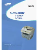
following figure shows the
temperature control procedure.
Power On
[See ]
ON
f)
1A-1)
degree C)
c)
C)
c)
Figure 2-20. Temperature for
Control Procedure
If the following conditions are detected, the printer indicates a
error (the LCD displays
SERVICE REQ.
. The thermistor temperature does notreach55°C
within 15 sec.
●
The warm-up period does notend within 120 seconds.
●
The thermistor temperature drops to
●
Thethermistortemperatureexceeds
The thermo fuse
cuts power
if
the temperature of the fusing section rises to an abnormally
high level (over
2.1.2.4 Scanner Mirror Motor Control
Figure 2-21 is the scanner mirror motor (M2) control circuit. ‘l’he scanner mirror motor is driven
while the scanner
motor
receives the SCANNER MIRROR MOTOR
signal.
Engine Controller Board
GND2
POLYGON MOTOR
LOCK
CLOCK
Motor
5
M2
3
2
1
Figure 2-21. Scanner Motor Control Circuit
Figure 2-22 is the scanner mirror motor driving timing chart. The scanner mirror motor rotates 0.15
seconds after the main motor (Ml) turns on. If the MIRROR
LOCK
signal is
not turned on within 3 seconds after the seamer mirror motor turns on, the printer indicates a
scanner mirror motor
malfunction.
Main Motor On
[sec.]
M2:ON
I
M2:LOCK
3.0
Figure 2-22. Scanner Motor Driving Start Timing
Rev.
2-11
Содержание ActionLaser 1000
Страница 1: ...EPSON TERMINAL PRINTER EPL 5000 5200 5200 1000 I15OO SERVICE MANUAL EPSON 4001962 ...
Страница 123: ...Appendix Laser 1000 1500 Service Manual c m 0 L v E Figure A 2 Cable Connections for the Engine Section A 2 Rev ...
Страница 133: ...Laser 100W15OO Service Manual Appendix I I I I 0 o Figure A 4 C82907 ROM B Board Circuit Diagram Rev ...
Страница 134: ...Manual 1 m 0 0 0 0 a 0 N 1 1 1 1 1 1 1 1 0 I 1 I VI Figure A 5 Control Panel Circuit Diagram A 14 Rev ...
Страница 135: ...Laser 100W15OO Service Manual Appendix 10 W Figure A 6 PWB A Board Circuit Diagram Rev A 15 ...
Страница 136: ...Appendix Laser 100LW5OO Service Manual W I u I z z II I em m m m m u Figure A 7 Basic Circuit Diagram u A 16 Rev A ...
Страница 138: ...Appendix Laser Service Manual 0 o 0 o o Figure A 9 C108 MAIN Board Component Layout Back Side Rev A ...
Страница 147: ...Appendix B Service Manual o 0 R m43 Figure B 5 CI08 MAIN B Board Component Layout Back B 10 Rev C ...
Страница 155: ...Service Manual Appendix C 0 ml 10 r 0 0 0 0 0 0 0 0 0 00 Figure C 2 C154 MAIN B Component Layout Front Rev E c 9 ...
Страница 157: ......