EPSON Stylus
COLOR
1520
Rev. A
3-28
3.2.10.11 Paper Load Roller Unit Removal
1. Remove the printer mechanism unit. (Refer to Section 3.2.6.)
2. Remove the paper eject frame. (Refer to Section 3.2.10.7.)
3. Remove the CR unit. (Refer to Section 3.2.10.9.)
4. Remove the base frame assembly. (Refer to Section 3.2.10.10.)
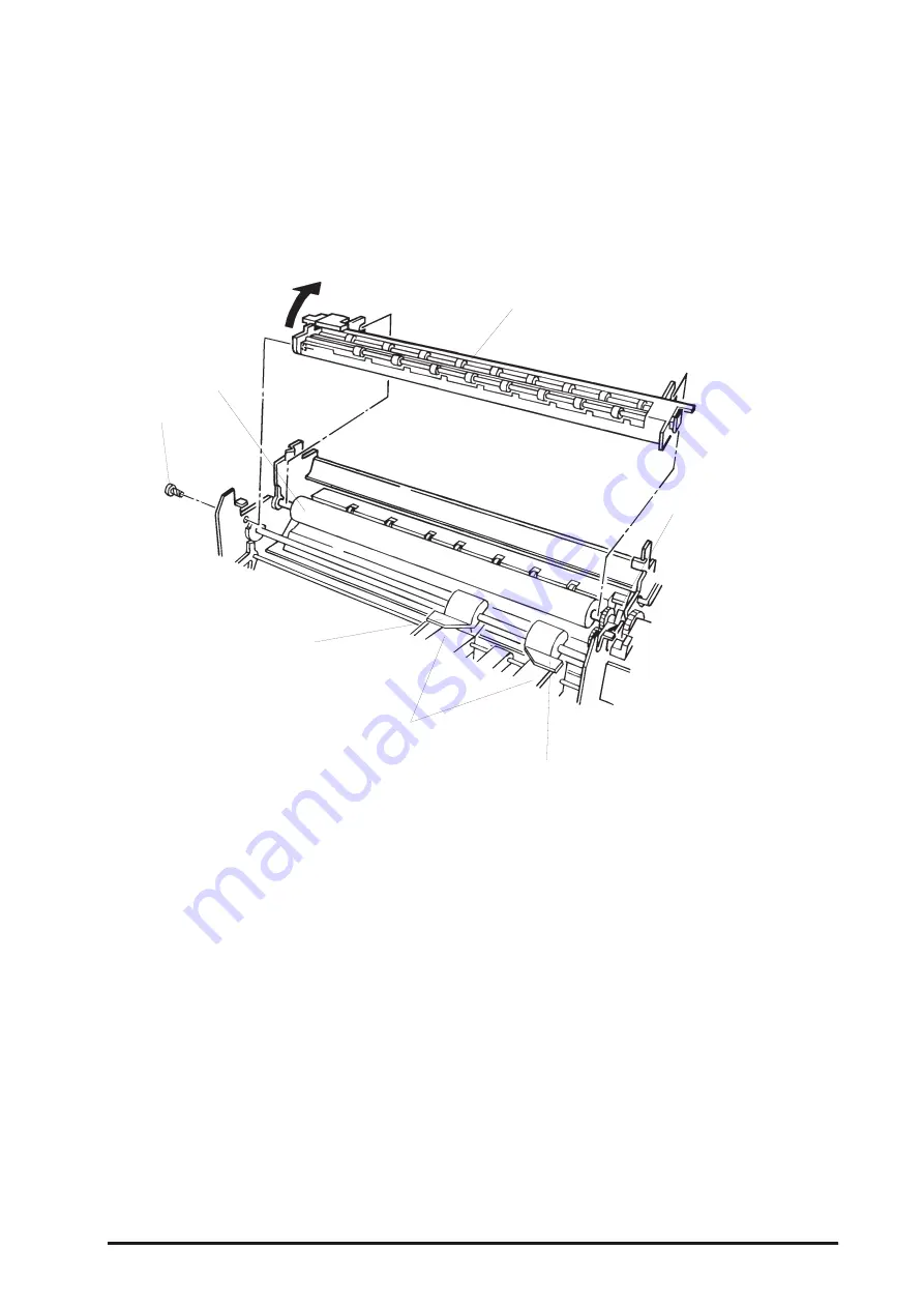
5. Attach the knob to the PF roller shaft, and press the trigger lever down. Then rotate the paper load
roller unit by turning the knob clock wise to hold the edge guide unit down.
6. Remove 1 screw (CBP, 3X8) securing the paper eject drive unit to the left frame assembly, and
remove the paper eject drive unit by lifting up the front edge.
7. Release the joints for the right and left slide covers and the edge guide.
8. Remove the E-ring located at left end of the paper load roller .
9. Adjust the paper load roller bushing with the cutout on the right frame.
10. Disengage the paper load gear at the right end of the paper load roller unit from the ASF
transmission gears in the middle frame. Then remove the paper load roller unit by sliding it toward
the left frame assembly.
Paper Eject Drive Unit
Trigger Lever
Right Slide Cover in the
Paper Load Roller Unit
Edge Guide Unit
Left Slide Cover in the
Paper Load Roller Unit
PF Roller Unit
Screw (CBP 3X8)
Figure 3-25. Paper Eject Drive Unit Removal
Содержание 1520 - Stylus Color Inkjet Printer
Страница 1: ...EPSON COLOR INK JET PRINTER EPSON Stylus COLOR 1520 SERVICE MANUAL SEIKO EPSON CORPORATION 4007394 ...
Страница 137: ...EPSON Stylus COLOR 1520 Rev A 6 4 1 1 1 2 2 3 3 3 4 5 6 6 6 6 6 6 7 7 7 7 Figure 6 1 Lubrication Points 1 ...
Страница 138: ...Maintenance Rev A 6 5 8 9 10 10 10 10 10 10 10 10 Figure 6 2 Lubrication Points 2 ...
Страница 139: ...EPSON Stylus COLOR 1520 Rev A 6 6 CR Motor CR motor fan Indent side facing outward 1 2 2 Figure 6 3 Adhesive Points ...
Страница 146: ...Appendix Rev A A 7 A 2 Circuit Diagrams Figure A A 2 C211 MAIN B Board Circuit Diagram 1 2 ...
Страница 147: ...EPSON Stylus COLOR 1520 Rev A A 8 ...
Страница 148: ...Appendix Rev A A 9 Figure A A 3 C211 MAIN B Board Circuit Diagram 2 2 ...
Страница 149: ...EPSON Stylus COLOR 1520 Rev A A 10 ...
Страница 152: ...Appendix Rev A A 13 A 3 Component Layout Figure A A 6 C211 MAIN B Board Component Layout ...
Страница 153: ...EPSON Stylus COLOR 1520 Rev A A 14 Figure A A 7 C172 PSB Board Component Layout ...
Страница 154: ...Appendix Rev A A 15 Figure A A 8 C172 PSE Board Component Layout ...
Страница 155: ...EPSON Stylus COLOR 1520 Rev A A 16 A 4 Exploded Diagrams Figure A A 9 Stylus COLOR 1520 Exploded Diagram 1 ...
Страница 156: ...Appendix Rev A A 17 Figure A A 10 Stylus COLOR 1520 Exploded Diagram 2 ...
Страница 157: ...EPSON Stylus COLOR 1520 Rev A A 18 Figure A A 11 Stylus Color 1520 Exploded Diagram 3 ...
Страница 165: ...EPSON SEIKO EPSON CORPORATION ...


