S a v e M o n e y a n d I m p r o v e Y o u r P r i n t i n g
MIS Associates Inc 2901 Auburn Rd. Auburn Hills, MI 48326 800-445-8296
http://www.inksupply.com Fax: 248-289-6013 Email: [email protected]
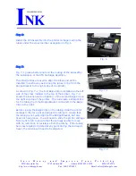
Step 6:
Install the CFS Assembly into the printer carriage routing the
tubes under the cross member as depicted in Fig. 6.
Fig. 6
Step 7:
Fig. 7-1 gives a better angle on the routing of the tubes after
the installation of the CFS Cartridge Assembly.
The 2 Beige Clips are used to align the tubes and will be
installed in such a way as to keep the tubes in line from the
Bridge Bracket to the right edge of the printer.
As shown in Fig. 7-2, the first Beige Clip is installed on the left
side of the cross member in the top of the printer. Fig. 7-3
shows the location and orientation of the second Beige Clip on
the right side top of the printer. This will create a straight line
for the tubing from the Bridge Bracket on the left to the Beige
Clip on the right.
Before closing the Beige Clips on the tubing, slide the printer
carriage to the far right and adjust the tubing to ensure that
the tubing is not pulled tight at the Bridge Bracket, but also
does not hang loose. You will need to slide the printer carriage
from right to left to ensure that the carriage is able to move
with no restriction or resistance from the tubing. If the tubing
becomes tangled or twisted at any point during the carriage's
travel, the tension will need to be adjusted.
Fig. 7-1
Fig. 7-2
Fig. 7-3


