E
P
S
G
r
m
a
n
y
Elektronische Lasten Serie
Electronic Load Series
EL 3000A
160V/60A/400W400V/25A/400W
EL 3160-60A: 35 320 200
EL 3400-25A: 35 320 201
Страница 1: ...E P S G e r m a n y Elektronische Lasten Serie Electronic Load Series EL 3000A 160V 60A 400W 400V 25A 400W EL 3160 60A 35 320 200 EL 3400 25A 35 320 201 ...
Страница 2: ......
Страница 3: ... Einschub zu bestücken müssen die einschlägigen ESD Vorschriften beachtet werden Die Schnittstellenkarte darf nur im ausgeschalteten Zustand aus dem Einschub herausgenommen oder bestückt werden Eine Öffnung des Gerätes ist nicht erforderlich Beachten Sie die Grenz bzw Nennwerte des Gerätes bei Anschluß einer Spannungsquelle oder Batterie sowie bei Benutzung der Analogschnittstelle Der DC Eingang i...
Страница 4: ...dung des DC Eingangs 9 5 5 Anschlussklemme Aux Fernfühlung 9 5 6 Steckplatz für Erweiterungskarte 9 6 Bedienung 10 6 1 Die Anzeige 10 6 2 Die Bedienelemente 11 6 3 Gerät einschalten 12 6 4 Ein und Ausschalten des Eingangs 12 6 5 Sollwerte einstellen 12 6 6 Regelungsarten vorwählen 12 6 7 Benutzung von Level A und Level B 13 6 7 1 Level A 14 6 7 2 Level B 14 6 7 3 Level A B Pulsbetrieb 14 6 7 4 Ans...
Страница 5: ...ls einer Schnittstellenkarte leicht möglich Deren Konfiguration ist einfach und wird am Gerät erledigt Die elektronischen Lasten können durch die zusätzliche analoge Schnittstelle auf der Front von einer analogen Steuereinheit z B SPS oder einem anderem Gerät mit analoger Schnittstelle gesteuert werden bzw dieses steuern Das Gerät ist mikroprozessorgesteuert Das erlaubt eine genaue und schnelle Me...
Страница 6: ...chaltung Batterietestfunktion Modi Strom Leistung Widerstand Strom Leistung Widerstand Batterieschutz Entladeschlußspannung einstellbar Entladeschlußspannung einstellbar Anzeige Zeit und verbrauchte Batteriekapazität Zeit und verbrauchte Batteriekapazität Anzeige 2 x 40 Zeichen beleuchtet 2 x 40 Zeichen beleuchtet Analoge Schnittstelle Steuereingänge 0 10V für U I P R 0 100 Nennwert 0 10V für U I ...
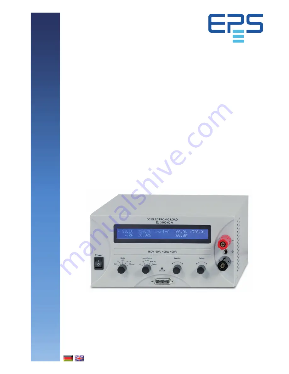
Страница 7: ... 3 1 Frontansicht Belegung AUX Klemmleiste S Senseeingang Plus S Senseeingang Minus Gnd Masse Triggerausgang Tr Triggerausgang Führt das pulsbreitenbestimmte interne Triggersignal als Rechteck heraus das sich durch die Einstellungen für den LevelA B Betrieb ergibt 3 2 Rückansicht Bild 1 Bild 2 ...
Страница 8: ... bis er durch die Input on off Taste bzw REM SB Pin der analogen Schnittstellen bei Fernsteuerung quittiert oder mittels digitaler Schnittstelle ausgelesen wird Ein interner Feh lerspeicher speichert bis zu drei aufgetretene Fehler und wird nach dem Auslesen gelöscht 4 6 Regelverhalten und Stabilitätskriterium Die elektronische Last zeichnet sich durch schnelle Stromanstiegs und abfallzeiten aus d...
Страница 9: ...A 2 x 6mm oder 1 x 16mm mindestens pro Anschlußleitung Litze frei verlegt zu verwenden Achtung Max Strom über die 4mm Büschelstec ker Kontakte 32A 5 4 Erdung des DC Eingangs Die Eingänge und sind erdfrei so daß bei Bedarf einer von beiden geerdet werden kann Achtung Bei Erdung einer der Eingangspole muß beachtet werden ob bei der Spannungsquelle z B Netzgerät nicht auch ein Ausgangspol geerdet ist...
Страница 10: ...r fail Eingangs spannungsfehler zeigen Alarmsituationen an Ein Eingangsspannungsfehler tritt auf wenn die Netz spannung zu niedrig ist Ein Überspannungsfehler wird bei zu hoher DC Eingangsspannung auftreten Für die DC Spannungsgrenze siehe 2 Technische Da ten Nach dem Auftreten einer der beiden Fehler ist der Lasteingang ausgeschaltet und kann nach Beseitigung der Ursache wieder eingeschaltet werd...
Страница 11: ...e Einstellung Keep set values yes gewählt wurde Bedeutung der einzelnen Schalterstellungen A Schaltet auf die Sollwerte für den Level A um Diese werden nach dem Umschalten sofort gesetzt B Schaltet auf die Sollwerte für den Level B um Diese werden nach dem Umschalten sofort gesetzt A B Schaltet die Last offline und aktiviert den Pulsbetrieb frequenzbehafter automatischer Wechsel zwischen Level A u...
Страница 12: ...in diesem Zustand keine sinnvollen Istwerte für Strom Leistung und Wider stand vorhanden sind Im Batterietestmodus wird durch das Betätigen des Tasters außerdem die Zeitmessung gestoppt bzw wieder gestartet Das Einschalten des Lastbetriebes kann durch bestimmte Umstände verhindert werden Zum Beispiel wenn eine Überspannung auftritt oder ein anderer Fehler vorliegt oder das Gerät über die analoge b...
Страница 13: ...alues auf no gestellt wurde Bei Auswahl yes werden die zuletzt eingestellten Sollwerte weiter benutzt Siehe auch 7 1 Das Einstellungs Menü CR bedeutet Konstantwiderstandsbetrieb aufgeteilt in zwei Bereiche Für die jeweiligen Werte siehe technische Daten Hinweis Die CR Regelungsart ist nur aktiv wenn der Wahlschalter Mode auf einem der beiden Widerstands bereiche steht Beide Bereiche verhalten sich...
Страница 14: ...es wird wiederum ein Pfeil vor den Wert gestellt Zusätzlich ist noch die Anstiegs Abfallzeit für den automatischen Wechsel vonA nach B und umgekehrt einstellbar Diese beiden Zeiten sind gleich daher können sie nicht für A und B getrennt eingestellt werden Bild 10 Level A B Betrieb mit Pulszeiteneinstellung Bild 9 Normaler Lastbetrieb in CP Regelungsart 6 7 1 Level A Bei Auswahl der Betriebsart Lev...
Страница 15: ...te im Format Wert Zeit Beispiel der Sollwert von A wurde auf 40A gesetzt und der von B auf 20A so wird ein Sollwertsprung von 20A in einer Zeit x z B 100ms erzeugt Angezeigt wird dies als 20A 100ms Der Wert ist hier an dieser Stelle nicht einstellbar Hinweis die Pulsbreiten von Level A und B sollten stets größer als die Anstiegszeit sein da sich sonst ein drei eckiges oder andersförmiges Sollwerts...
Страница 16: ...eht kann der Batterietest wieder ausgeführt werden Die Zeit und Ah Zählwerte sind allerdings zurückgesetzt Hinweis wird im Batterietestmodus die Regelungsart geändert werden alle anderen Sollwerte die in der gewählten Regelungsart nicht vom Anwender gesetzt werden können auf Standardwerte gesetzt damit der Modus funktioniert Hie r wirkt die Einstellung Keep set values somit nicht Im in Bild 13 gez...
Страница 17: ... System normal gesetzt wurde siehe oben 7 Gerätekonfiguration 7 1 Das Einstellungs Menü Das Einstellungs Menü kann nur mit dem Schalter Level Control 3 auf Stellung Setup aktiviert werden außer bei Fernsteuerbetrieb Solange die Last in der Betriebsart Setup ist ist kein normaler Lastbetrieb möglich In der Anzeige werden für den Betrieb benötigte Para meter angezeigt die mit Selection 5 ausgewählt ...
Страница 18: ... zum Senden von Broad castnachrichten an mehrere Geräte deren Broadcast IDs gleich eingestellt wurden Diese Geräte wenn auf dieser ID angesprochen machen dann parallel und zeitgleich dasselbe wie z B eine Stromsollwert setzen Über diese ID können nur Sollwerte bzw Zustände gesendet aber nichts angefragt werden Hinweis nur verfügbar wenn CAN ID System Vector gesetzt wurde siehe oben CAN Bus termina...
Страница 19: ...n der Widerstandsbereich wie beim Schalter MODE vorge wählt bzw während des Betriebes umgeschaltet wer den Nichbeschaltung des Pins also HIGH aktiviert den kleinen Widerstandsbereich CR1 Pin 13 R Range dient zur Umschaltung Pin 13 Low Bereich CR2 groß aktiv Pin 13 High Bereich CR1 klein aktiv Der Eingang Rem SB Remote Standby Pin 8 über lagert die Taste Input on off 4 Das heißt wenn die Last mit d...
Страница 20: ...nktion ist immer nutzbar und erfordert nicht die Umschaltung auf AS Steuerung mit Pin Remote Sie kann mit anderenAnwen dungen kombiniert und durch verschiedene Kontaktarten Transistor Relais Schalter usw realisiert werden Freigabe des Kontaktes schaltet den Eingang wieder ein Fernsteuerung sofern er vorher eingeschaltet war bzw läßt das manuelle Einschalten über die Frontbedienele mente wieder zu ...
Страница 21: ...en AGND DI Widerstandsregelung ein aus 1 R Regelung aus LOW U Low 1V U Bereich 0 30V R Regelung ein HIGH U High 4V oder offen I Max 1mA bei 5V DI Umschaltung Widerstands R nenn Widerstandsbereich 2 LOW U Low 1V U Low to High typ 3V bereich 4 R nenn Widerstandsbereich 1 HIGH U High 4V oder offen Sender Offener Kollektor gegen DGND DI Triggereingang triggert A B LOW U Low 1V triggert B A HIGH U High...
Страница 22: ...n erfordern unterschiedliche Einstellungspara meter Diese sind im Abschnitt 7 Gerätekonfiguration beschrieben Weitere Informationen sowie technische Daten zu den einzelnen Schnittstellen finden Sie in deren Benutzer handbuch Besonderheiten Die Steuerung über die Schnittstellenkarten folgt bei Verwendung der mitgelieferten LabView Bausteine den Gegebenheiten des Gerätes Sollwerte werden auf Plausib...
Страница 23: ... USB RS232 CAN GPIB IEEE SCPI oder Ethernet LAN SCPI sind erhältlich 10 2 Firmware Aktualisierung Falls eine Aktualisierung der Gerätefirmware nötig sein sollte so kann dies vom Anwender selbst erledigt wer den Dazu wird auf Anfrage eine entsprechende neue Version der Firmware sowie ein Windowsprogramm zur Verfügung gestellt daß die Aktualisierung vornimmt Voraussetzung für die Aktualisierung ist ...
Страница 24: ......
Страница 25: ...460VDC 400V model In order to equip interface cards into the slot at the rear the common ESD provisions have to be followed The interface card may only be plugged and unplugged while the unit is completely switched off mains switch OFF Always observe limit and nominal values of the device when connecting a voltage source or battery as well as when using the analogue interface The DC input is not f...
Страница 26: ...nding the DC input 31 5 5 Terminal AUX remote sense 31 5 6 Interface card slot 31 6 Handling 32 6 1 The display 32 6 2 Operating elements 33 6 3 Switching power on 34 6 4 Switching the DC input on off 34 6 5 Adjusting the set values 34 6 6 Preselecting the regulation mode 34 6 7 Usage of Level A and Level B 35 6 7 1 Level A 35 6 7 2 Level B 36 6 7 3 Level A B pulsed operation 36 6 7 4 Rise fall ti...
Страница 27: ...g and use up to four or more devices to a standard PC without the need of additional hardware With CAN you can implement the devices into existing CAN bus systems without the need to reconfigure the whole bus Address range and trans missions speed can be selected for the particular EL 3000 A unit to meet the given requirements The main functions at a glance Set U I P and R each 0 100 Battery test ...
Страница 28: ...ure Modes Current Power Resistance Current Power Resistance Battery protection Discharge threshold voltage adjustable Discharge threshold voltage adjustable Display Time and comsumed battery capacity Time and comsumed battery capacity Display 2 x 40 characters illuminated 2 x 40 characters illuminated Analogue interface Set value inputs 0 10V for U I P R 0 100 0 10V for U I P R 0 100 Monitor outpu...
Страница 29: ... view 3 2 Rear view Figure 1 Figure 2 Pin assignment of AUX terminal S positive Sense input S negative Sense input Gnd Ground of trigger output Tr Trigger output Leads out the pulse width determined internal trigger signal as a square wave which results from the settings in Level A B operation ...
Страница 30: ...buffer stores up to three different alarms and is purged when read 4 6 Dynamic characteristics and stability criteria The electronic load is characterised by short rise and fall times of the current which are achieved by a high bandwidth of the internal regulation circuit In case of testing sources with own regulation circuits at the load like for example power supplies a regulation instability ma...
Страница 31: ...y plug contacts 32A 5 4 Grounding the DC input The inputs und are not grounded so that one of them may be grounded if necessary Attention When grounding one of the input poles always check if one of the output poles of the source eg power supply is also grounded This could result in a short circuit 5 5 Terminal AUX remote sense The remote sense feature is wired at terminal AUX In order to compensa...
Страница 32: ...ement The signals Overvoltage Overtemperature or Power fail indicate the presence of an alarm situation Apower fail alarm occurs if the mains input voltage is too low An overvoltage alarm is indicated if the overvoltage limit for the DC input has been exceeded see 2 2 Device specific data for the limit Both alarms switch the load input off After removal of the cause it can be put online again An o...
Страница 33: ...ns undervoltage power fail and are restored after switching it on again if the setting Keep set values yes has been chosen Explanation of the selector positions A Switches to the set values of Level A These values become instantly active and can be changed now B Switches to the set values of Level B These values become instantly active and can be changed now A B Switches the load offline and activ...
Страница 34: ...n the cur rently selected regulation mode are not shown Set values can be selected and adjusted as long as the display does not show the status texts External mode or Remote mode a Selecting the set value to adjust In the operation modes A B A B and Battery the set value to change is selected by rotating Selection 5 In the setup menu position Setup it is used to select a different setup parameter ...
Страница 35: ...sted resistance can also not be achieved The manual changeover to regulation mode CR can reset the set values of resistance current and power to their nominal values if the parameter Keep set values has been set to no in the setup If set to yes the least adju sted set values are kept Also see 7 1 The setup menu 6 7 Usage of Level A and Level B Introduction The terms Level A and Level B stand for t...
Страница 36: ... on the analogue interface is only availab le in LevelA B mode The trigger input has to be activated in the setup menu with the option Trigger mode see 7 Device configuration The default setting is internal By setting it to external the switchover between A and B can only be done via the trigger input Handling the device The adjusted rise fall time is still effective here but the pul se widths are...
Страница 37: ...played as the consumed battery capacity in Ah The voltage supervision together with the adjustable undervoltage shutdown threshold Ulow prevents the battery from being deeply discharged This threshold needs to be adjusted at least once If it is exceeded du ring the test the load input is automatically switched off and the time counter is halted No more current is drawn from the battery If the thre...
Страница 38: ... external control while remote control is active the remote control status would be reset and the device would only be controllable via the analogue inputs In order to report this to a software running on a PC still trying to access and control the device the control loca tion is internally set to local In local status the device can only be read i e monitored by the PC 6 10 Series and parallel co...
Страница 39: ...locatable ID so that no collision can occur Hence there are theoretically 32 x 30 possible device nodes with two IDs each available when using CAN 7 Device configuration 7 1 The setup menu The setup menu can only be activated by the selector Level 3 except during remote control While the load is in setup no normal load operation is possible The display shows a certain number of parameters dependin...
Страница 40: ...astmessages to multiple bus members at once Those units when addressed by this ID will act the same time executing the same command like setting current With this ID only settings or values can be sent and nothing can be queried Note this setting is only availabe if CAN ID System Vector has been selected see above CAN Bus terminate Possible settings yes no Default setting yes since firmware 5 01 e...
Страница 41: ...rface Pin 13 R Range is used to switch between the two ranges Pin 13 Low Resistance range 2 is used Pin 13 High Resistance range 1 is used default Remote control The input Rem SB Remote Standby Pin 8 overlays the pushbutton Input on off 4 That means that you can switch the load input off or on with this pin at any time even if the load was not set to external control via the analogue interface and...
Страница 42: ...d does not require the activation of external control by pin Remote It can be combined with other applications and can be realised by various contacts like transistors relays switches etc Opening the contact again will either switch the output on if it was on before switching off remote control or enable switching it on again manually on the front panel DGND REM SB DGND REMOTE Figure 18 Switching ...
Страница 43: ...100 of I Nom Short circuit proof against AGND AO Accuracy typically 0 1 at I Max 5mA Short circuit proof against AGND DI Selection R on R off 1 R regulation off LOW U Low 1V U range 0 30V R regulation on HIGH U High 4V or open I Max 1mA at 5V DI Select resistance range 4 RMax resistance range 2 LOW U Low 1V U Low to High typ 3V RMax resistance range 1 HIGH U High 4V or open Sender open collector a...
Страница 44: ...ntrol of the electronic load via one of the interface cards and the supplied LabView VIs follows the operating conditions and nominal values of the device Set values are checked for plausibility and are corrected if necessary or forced to nominal values LabView We provide ready to use LabView VIs for the interface cards These do not support all of the features of the electronic load but are consta...
Страница 45: ... retrofittable digital interface cards for USB RS232 CAN GPIB IEEE SCPI only or Ethernet LAN SCPI are available 10 2 Firmware updates If a firmware update becomes necessary it can be done by the user Upon request we supply a new firmware version and an update tool for Windows which will per form the update In order to do an update either a card of type IF R1 IF U1 or IF E1 is required Other interf...
Страница 46: ......
Страница 47: ......
Страница 48: ......