background image

Introduction

EP-6WEA4/4I

Page 1-2

Overview

Pentium

®

 II or Pentium

®

 III Processor

The Pentium

®

 II or Pentium

®

 III Processor (The Pentium

®

 III Processor as 350~600/

100MHz and 533~733/133MHz speed or above with 512K/256K-L2 cache
Versions.) is the follow-on to the Pentium

®

 Processor.  The Pentium

®

 II or Pentium

®

III Processor, like the Pentium

®

 Pro processor, implements a Dynamic Execution

micro-architecture -- a unique combination of multiple branch prediction, data flow
analysis, and speculative execution.  This enables the Pentium

®

 II/III Processor to

deliver higher performance than the Pentium

®

 processor, while maintaining binary

compatibility with all previous Intel architecture processors.

A significant feature of the Pentium

®

 II or Pentium

®

 III Processor, from a system

perspective, is the built-in direct multiprocessing support.  In order to achieve
multiprocessing, and maintain the memory and I/O bandwidth to support it, new
system designs are needed.  For systems with dual processors, it is important to
consider the additional power burdens and signal integrity issues of supporting
multiple loads on a high speed bus.  The Pentium

®

 II or Pentium

®

 III Processor

card supports both uni-processor and dual processor implementations.

The Pentium

®

 II or Pentium

®

 III Processor utilizes Single Edge Contact (S.E.C.)

(Figure 1) cartridge packaging technology.  The S.E.C. cartridge allows the L2
cache to remain tightly coupled to the processor, while maintaining flexibility
when implementing high performance processors into OEM systems.  The second
level cache is performance optimized and tested at the cartridge level.  The S.E.C.
cartridge utilizes surface mounted core components and a  printed circuit board
with an edge finger connection.  The S.E.C. cartridge package introduced on the
Pentium

®

 II Processor will also be used in future Slot 1 processors.

The S.E.C. cartridge has the following features: a thermal plate, a cover and a PCB
with an edge finger connection.  The thermal plate allows standardized heatsink
attachment or customized thermal solutions.  The thermal plate enables a reusable
heatsink to minimize fit issues for serviceability, upgradeability and replacement.
The full enclosure also protects the surface mount components.  The edge finger
connection maintains socketabilty for system configuration.  The edge finger
connector is denoted as ‘Slot 1 connector’ in this and other documentation.

Содержание EP-6WEA4

Страница 1: ...tium II or P II or P II or P II or P II or Pentium entium entium entium entium III Slot1 III Slot1 III Slot1 III Slot1 III Slot1 Pr Pr Pr Pr Processor based ocessor based ocessor based ocessor based ocessor based A A A A AGP mainboar GP mainboar GP mainboar GP mainboar GP mainboard d d d d 133 100 66MHz 133 100 66MHz 133 100 66MHz 133 100 66MHz 133 100 66MHz EP 6WEA4 EP 6WEA4 EP 6WEA4 EP 6WEA4 EP ...

Страница 2: ...notice For updated BIOS drivers or product release information you may visit our websites at http www epox com or http www epox com tw Products mentioned in this manual are mentioned for identification purposes only Product names appearing in this manual may or may not be registered trademarks or copyrights of their respective companies The product name and revision number are both printed on the ...

Страница 3: ...ber __________________________ Contacting Technical Support EPoX technical support is working hard to answer all of your questions online From our website you can find answers to many common questions drivers BIOS updates tech notes and important technical bulletins If you are still unable to locate the solution you are seeking you always have the option to contact our support technicians directly...

Страница 4: ...es 2 1 Section 3 Installation EP 6WEA4 4I Detailed Layout 3 2 Easy Installation Procedure Configure Jumpers 3 3 AC 97 MR Configuration Table 3 4 System Memory Configuration 3 5 Installing a Pentium II III Processor 3 7 Device Connectors 3 9 External Modem Ring in Power ON and Keyboard Power ON Function KBPO 3 11 STR Suspend To RAM Function 3 13 Section 4 Award BIOS Setup Main Menu 4 1 Standard CMO...

Страница 5: ...word Setting 4 26 ExitSelecting 4 27 Section 5 810E VGA and Sound Driver Installation Easy Driver Installation 5 1 Appendix Appendix A Memory Map A 1 I O Map A 1 Timer DMA Channels Map A 2 Interrupt Map A 2 RTC CMOS RAM Map A 3 Appendix B POST Codes A 5 Appendix C Load Optimized Defaults A 13 Appendix D GHOST 5 1 Quick User s Guide A 15 ...

Страница 6: ...EP 6WEA4 4I Page Left Blank ...

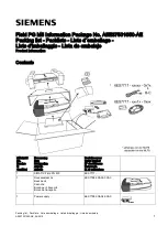
Страница 7: ...nboard ü ü ü ü ü B 1 EP 6WEA4 4I user s manual ü ü ü ü ü C 1 Floppy ribbon cable ü ü ü ü ü D 1 ATA 66 Hard driver ribbon cables ü ü ü ü ü E 1 Foldable Retention Module F 1 PS 2 to AT keyboard connector adapter optional ü ü ü ü ü G 1 Onboard Graphic and Sound Driver USER S MANUAL EP 6WEA4 4I B A F C D E G or ...

Страница 8: ...s on a high speed bus The Pentium II or Pentium III Processor card supports both uni processor and dual processor implementations The Pentium II or Pentium III Processor utilizes Single Edge Contact S E C Figure 1 cartridge packaging technology The S E C cartridge allows the L2 cache to remain tightly coupled to the processor while maintaining flexibility when implementing high performance process...

Страница 9: ...ious names for packaging technology such as PGA or TCP Processor card The green PCB with or without components on it Processor core The silicon on the PLGA package on the PCB Cover The plastic cover on the opposite side from the thermal plate Slot 1 The slot that the S E C cartridge plugs into just as the Pentium Pro processor uses Socket 8 Retention mechanism Formerly retention module the dual po...

Страница 10: ... video quality The Inte R 82810E chipset use Intel R Dynamic Video Memory Technology D V M T is an architecture that offers breakthrough performance for the motherboard PC through efficient memory utilization and Direct AGP The system OS uses the Intel software drivers and intelligent memory arbiter to support richer graphics applications The 82801AA I O Controller Hub ICH employs the Intel R Acce...

Страница 11: ...g a redundant nonvolatile memory component In addition the 82802AB contains a hardware Random Number Generator RNG The Intel R RNG provides truly random numbers to enable fundamental security building blocks supporting stronger encryption digital signing and security protocols for the future application program ...

Страница 12: ... and position of this aperture is defined allowing PC manufacturers to add new I O features e g TV input TV output joystick modem LAN etc to systems This will help systems integrators differentiate their products in the marketplace and better meet your needs Smaller size promotes a smaller system size I O shield does not need to be retooled in an ATX 2 01 or later The mainboard should be used in a...

Страница 13: ... momentary button that is normally open The EP 6WEA4 4I has been designed with Soft Off functions You can turn Off the system from one of two sources The first is the front panel Power On Off the button and the other is the Soft Off function coming from the EP 6WEA4 4I s onboard circuit controller that can be controlled by the operating system Windows 95 98 will control this when the user clicks t...

Страница 14: ...Introduction EP 6WEA4 4I Page 1 8 Figure 5 System Block Diagram System Block Diagram ...

Страница 15: ... 230MHz DAC and 4MB Display Cache AC 97 2 1 Audio CODEC onboard for enables the software Audio Supports 5 32 bit PCI slots provides 2 independent high performance PCI IDE interfaces capable of supporting PIO Mode 3 4 and Ultra DMA 66 devices The EP 6WEA4 4I supports 5 PCI Bus Master slots and a jumperless PCI INT control scheme which reduces configuration confu sion when plugging in PCI card s Sup...

Страница 16: ...turn on at a preselected time Supports CPU Hardware sleep and SMM System Management Mode Supports Hot key Any key or password Keyboard power ON function KBPO Supports the CPU PWR and Chassis fan Auto stop in the sleep mode Supports the System Power LED PANEL blinks in the sleep mode Built in WOL Wake On Lan Connector Supports the AMR Connector for enables the software modem Y2K Compliant Advanced ...

Страница 17: ...Installation EP 6WEA4 4I Page 3 1 Section 3 INSTALLATION ...

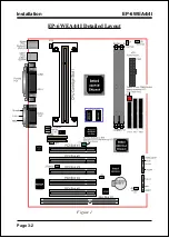
Страница 18: ...Installation EP 6WEA4 4I Page 3 2 Figure 1 EP 6WEA4 4I Detailed Layout ...

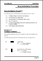
Страница 19: ...ium III Processor 3 4 Device Connectors 3 5 External Modem Ring in Power ON and Keyboard Power ON Functions KBPO 3 6 STR Suspend To RAM Function Section 3 1 Configure Jumpers We design this mainboard with the a few jumpers to make your installation fast and easy The following will describe all of the jumpers that you are required to set 1 JP1 CMOS Clear JP1 1 2 Normal Default 2 3 Clear CMOS JP13 K...

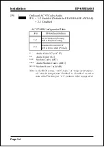
Страница 20: ... i r P d r a o b n O 7 9 C A y r a d n o c e S C M r o R M 3 2 7 9 C A d r a o b n O d e l b a s i D y r a m i r P C M A r o C M r o R M Audio Codec 97 AC 97 Audio Codec AC Modem Codec MC Audio Modem Codec AMC Modem Riser Card MR Note In the BIOS setting AC97 Audio of Integrated Peripher als must be changed from Enabled to Disabled as well to come with JP8 setting at 2 3 position refer to page 4 1...

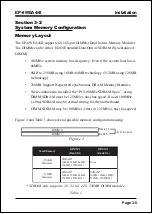
Страница 21: ...MHz SDRAM Spec using DIMM SDRAM must be 125MHz 8ns bus speed If used 100MHz 10ns SDRAM may be critical timing for the motherboard DIMM SDRAM may be 100MHz 10ns or 125MHz 8ns bus speed Figure 2 and Table 1 show several possible memory configurations using SDRAM only supports 16 32 64 128 256MB DIMM modules Table 1 y r o m e M l a t o T 1 M M I D 1 0 k n a B 2 M M I D 3 2 k n a B B M 6 5 2 m u m i x...

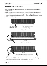
Страница 22: ...re installed by placing the chip firmly into the socket at a 90 degree angle and pressing straight down figure 4 until it fits tightly into the DIMM socket figure 5 Figure 3 Figure 5 DIMM Module clip after installation To remove the DIMM module simply press down both of the white clips on either side and the module will be released from the socket Figure 4 DIMM Module clip before installation CENT...

Страница 23: ...tium II III Retention Mechanism This pre installed device is designed for you to install Pentium II III CPU more easier and to avoide any damage on the board due to overtightening the four screws One thing must be kept in your mind that please make sure to lift upright the foldable parts of the Retention module to fit and install CPU properly Figure 6 Now we are going to put the heatsink or cooler...

Страница 24: ... Cache Type CPUID3 533EB1 533 133 256 ATC2 068xh 550E1 550 100 256 ATC2 068xh 600E1 600 100 256 ATC2 068xh 600EB1 600 133 256 ATC2 068xh 650E1 650 100 256 ATC2 068xh 667EB1 667 133 256 ATC2 068xh 700E1 700 100 256 ATC2 068xh 733EB1 733 133 256 ATC2 068xh The table listing all Coppermine processor identification Notes 1 B 133MHz System Bus Frequency E Processor with Advanced Transfer Cache CPUID 06...

Страница 25: ... so that BIOS can monitor the RPM s J6 Chassis Fan Power A plug in for the chassis Fan Power J7 WOL Wake On Lan Connector PW2 ATX Power Connector 20 pin power connector IDE1 Primary IDE Connector IDE2 Secondary IDE Connector FDD1 Floppy Controller Connector CD IN CD Audio_IN Connector Pin1 CD_IN_Left Pin2 Pin3 GND Pin4 CD_IN_Right AUX_IN Auxiliary Line_IN Connector Pin1 Left Line_IN Pin2 Pin3 GND ...

Страница 26: ...choose either Instant Off turns system off immediatly or 4 sec delay you need to hold the button down for 4 seconds before the system turns off When the system is in 4 sec delay mode there is a special feature to make the system to go into suspend mode when the button is pressed momentarily Turbo LED indicator LED ON when higher speed is selected IDE LED indicator LED ON when Onboard PCI IDE Hard ...

Страница 27: ...tep 1 Please check JP13 at the position 1 2 after you finished the system installation Step 2 Push the momentary switch J3 PW ON to turn on your system and then push again to hold for more than 4 seconds to turn it off affter counting memory as soon as you turn it on Step 3 You can enjoy the Keyboard Power ON function KBPO by pressing any 1 key Hot key Ctrl F1 F2 F12 Password A maximum of 5 charac...

Страница 28: ... 5 0VSB standby power only has to be 0 1A 100mA then you can enjoy this unique benefit However the ATX power supply which is 0 1 100mA is still applicable to your system by placed JP13 at the position 2 3 to disable this feature 2 We recommended you use the power supply with 1 0A in 5 0VSB Because this supported PCI 2 1 specification for remote power on and wake up function ...

Страница 29: ...indows 98 installed in your system without the parameters above please do refer your manual or contact Microsoft for more detail and then upgrade the system to support ACPI function c Restart your system and install 810 VGA driver properly d Getting in to the Advanced of the Power Management icon of Control Panel and selecting the Stand By in the Power Buttons 2 Getting start with STR function ple...

Страница 30: ...anking ON D23 Red LED ON ON ON ON OFF J2 PW_LED OFF ON Blanking OFF OFF d You must push the Power button connected with onboard J3 pin to wake up you system not to click to mouse or press keyboard to wake up the system Just pushing Power button your system will quickly back to the last screen for you The LED Indicator for ACPI Status table shown below will guide you and give you a reference for AC...

Страница 31: ...ces Use the arrow keys to select among the items and press Enter to accept and enter the sub menu Note that a brief description of each highlighted selection appears at the bottom of the screen Setup Items The main menu includes the following main setup categories Recall that some systems may not include all entries Standard CMOS Features Use this menu for basic system configuration Section 4 BIOS...

Страница 32: ...us include Voltage Fan speed CPU temperature Frequency Voltage Control Use this menu to specify your settings for frequency voltage control Load Fail Safe Defaults Use this menu to load the BIOS default values for the minimal stable perfor mance for your system to operate Load Optimized Defaults Use this menu to load the BIOS default values that are factory settings for opti mal performance system...

Страница 33: ... in Standard CMOS Setup Menu are divided into 10 categories Each cat egory includes no one or more than one setup items Use the arrow keys to high light the item and then use the PgUp or PgDn keys to select the value you want in each item Figure 1 The Main Menu ...

Страница 34: ...Enter to enter the sub menu of detailed options Drive A Drive B None 360K 5 25 in 1 2M 5 25 in 720K 3 5 in 1 44M 3 5 in 2 88M 3 5 in Select the type of floppy disk drive installed in your system Floppy 3 Mode Support Disabled Drive A Drive B Both Video EGA VGA CGA 40 CGA 80 MONO Select the default video device Halt On All Errors No Errors All but Keyboard All but Diskette All but Disk Key Select t...

Страница 35: ...4 4I Page 4 5 IDE Adapters The IDE adapters control the hard disk drive Use a separate sub menu to configure each hard disk drive Figure 2 shows the IDE primary master sub menu Figure 2 IDE Primary Master sub menu ...

Страница 36: ...rs heads etc Note PRECOMP 65535 means NONE Capacity Auto Display your disk drive size Disk drive capacity Approximated Note that this size is usually slightly greater than the size of a formatted disk given by a disk checking program Access Mode Normal LBA Large Auto Choose the access mode for this hard disk The following options are selectable only if the IDE Primary Master item is set to Manual ...

Страница 37: ...enabled and someone attempt to write data into this area BIOS will show a warning message on screen and alarm beep Enabled Activates automatically when the system boots up causing a warning message to appear when anything attempts to access the boot sector or hard disk partition table Disabled No warning message will appear when anything attempts to access the boot sector or hard disk partition ta...

Страница 38: ...quick POST Disabled Normal POST First Second Third Other Boot Device The BIOS attempts to load the operating system from the devices in the sequence selected in these items The Choice Floppy LS ZIP HDD SCSI CDROM Disabled Swap Floppy Drive If the system has two floppy drives you can swap the logical drive name assignments The choice Enabled Disabled Boot Up Floppy Seek Seeks disk drives during boo...

Страница 39: ... when you enter setup System The system will not boot and access to Setup will be denied if the correct password is not entered at the prompt Setup The system will boot but access to Setup will be denied if the correct password is not entered at the prompt Note To disable security select PASSWORD SETTING at Main Menu and then you will be asked to enter password Do not type anything and just press ...

Страница 40: ...he default settings have been chosen be cause they provide the best operating conditions for your system The only time you might consider making any changes would be if you discovered that data was being lost while using your system DRAM Settings The first chipset settings deal with CPU access to dynamic random access memory DRAM The default timings have been carefully chosen and should only be al...

Страница 41: ...video BIOS resulting in better system performance However if any program writes to this memory area a system error may result The Choice Enabled Disabled Video RAM Cacheable This option allows the CPU to cache read writes of the video RAM The default is Enabled Enabled This option allows for faster video access Disabled Reduced video performance Memory Hole At 15M 16M You can reserve this area of ...

Страница 42: ...ge 4 12 On Chip Video Window Size The amount of system memory that the 810 AGP is allowed to share The default is 64 32 32MB of systems memory accessable by the 810 AGP 64 64MB of systems memory accessable by the 810 AGP ...

Страница 43: ...d IDE interface supports Modes 0 through 4 provide successively increased performance In Auto mode the system automatically determines the best mode for each device The choice Auto Mode 0 Mode 1 Mode 2 Mode 3 Mode 4 IDE Primary Secondary Master Slave UDMA Ultra DMA 33 implementation is possible only if your IDE hard drive supports it and the operating environment includes a DMA driver Windows 95 O...

Страница 44: ...led IDE HDD Block Mode Block mode is also called block transfer multiple commands or multiple sector read write If your IDE hard drive supports block mode most new drives do select Enabled for automatic detection of the optimal number of block read writes per sector the drive can support The choice Enabled Disabled Power On Function There are Button Only Hot Key and Any key can be chosen by this f...

Страница 45: ... Ctrl F10 Ctrl F11 and Ctrl F12 Onboard FDC Controller Select Enabled if your system has a floppy disk controller FDC installed on the system board and you wish to use it If you install and in FDC or the system has no floppy drive select Disabled in this field The choice Enabled Disabled Onboard Serial Port 1 Port 2 Select an address and corresponding interrupt for the first and second serial port...

Страница 46: ...bilities Port mode EPP ECP ECP Mode EPP Mode EPP Mode Select This item allows you to determine the IR transfer mode of onboard I O chip options EPP1 9 EPP1 7 ECP Mode USE DMA This field allows the user to select DMA1 or DMA3 for the ECP mode The default is DMA3 DMA1 This field selects the routing of DMA1 for the ECP mode DMA3 This field selects the routing of DMA3 for the ECP mode PWRON After PW F...

Страница 47: ...BIOS EP 6WEA4 4I Page 4 17 Mida Port Address Select an address for the Mida port The choice 290 300 330 Disabled Midi Port IRQ Select an interrupt for the Mida port The choice 5 10 ...

Страница 48: ...r use ACPI Function This item allows you to enable disable the Advanced Configuration and Power Man agement ACPI The choice Enabled Disabled ACPI Suspend Type This item allows you to select S1 POS or S3 STR function The choice S1 POS S3 STR Power Management This category allows you to select the type or degree of power saving and is di rectly related to the following modes 1 HDD Power Down 2 Doze ...

Страница 49: ...h ranges from 1 min to 15 min and disable Video Off Method This determines the manner in which the monitor is blanked V H SYNC Blank This selection will cause the system to turn off the vertical and horizontal synchronization ports and write blanks to the video buffer Blank Screen This option only writes blanks to the video buffer DPMS Initial display power management signaling Video Off In Suspen...

Страница 50: ... Wake on LAN WOL features The choice Enabled Disabled CPU THRM Throttling Select the CPU THRM Throttling rate The choice 25 0 37 5 50 0 62 5 75 0 87 5 Resume by Alarm This option allows you to have the system turn on at a present time each day or on a certain day The choice Disabled Enabled PM Events PM events are I O events whose occurrence can prevent the system from entering a power saving mode...

Страница 51: ...e any changes to the default settings Reset Configuration Data Normally you leave this field Disabled Select Enabled to reset Extended System Configuration Data ESCD when you exit Setup if you have installed a new add on and the system reconfiguration has caused such a serious conflict that the operating system can not boot The choice Enabled Disabled Resource controlled by The Award Plug and Play...

Страница 52: ...rces by going into each of the sub menu that follows this field a sub menu is preceded by a Ø The choice Auto ESCD Manual PCI VGA Palette Snoop Leave this field at Disabled Choices are Enabled Disabled INT Pin1 to Pin4 Assignment These settings allow the user to specify what IRQ will be assigned to PCI devices in the chosen slot Options available Auto 3 4 5 7 9 10 11 12 14 15 The defaults are Auto...

Страница 53: ... CPU V The voltage level of the Vtt Vcore Vcc 5V 12V 12V 5V VBAT 5VSB The voltage level of the switch power supply Shutdown Temperature This is the temperature that the computer will turn off the power to combat the effects of an overheating system requires ACPI to be enabled in Power Manage ment BIOS and ACPI compliant operating system The default is 100o C 212o F Options available are 60o C 140o...

Страница 54: ...is designed to set the CPU Host AGP PCI clock at jumperfree This item allows you to select the CPU Host speed and PCI clock speed by Enter key If default is means the CPU Host speed that depend on the CPU is 100MHz or 133MHz CPU Clock Ratio This item allows you to select the CPU ratio If the CPU ratio is fixed This item was no function Configuration options 3 x 7x 7 5x 8 x CPU Vcore Voltage This i...

Страница 55: ...log box with a message similar to Load Fail Safe Defaults Y N N Pressing Y loads the BIOS default values for the most stable minimal perfor mance system operations Load Optimized Defaults When you press Enter on this item you get a confirmation dialog box with a message similar to Load Optimized Defaults Y N N Pressing Y loads the default values that are factory settings for optimal perfor mance s...

Страница 56: ...rt the selection and not enter a password To disable a password just press Enter when you are prompted to enter the password A message will confirm the password will be disabled Once the pass word is disabled the system will boot and you can enter Setup freely PASSWORD DISABLED When a password has been enabled you will be prompted to enter it every time you try to enter Setup This prevents an unau...

Страница 57: ...u turn your system off The next time you boot your computer the BIOS configures your system according to the Setup selections stored in CMOS After saving the values the system is restarted again Exit Without Saving Pressing Enter on this item asks for confirmation Quit without saving Y N Y This allows you to exit Setup without storing in CMOS any change The previous selections remain in effect Thi...

Страница 58: ...BIOS EP 6WEA4 4I Page 4 28 Page Left Blank ...

Страница 59: ...rosoft Windows 95 OSR 2 1 and Windows 98 oper ating systems Step 2 To Click the Intel 810 and 820 INF Installation Utility This installer will install updated INF files onto the target machine Supported operating systems Microsoft Windows 95 OSR 2 1 and Windows 98 operating systems This procedure will Re start the system Step 3 To Click the Intel 810 VGA Driver to installation the Graphics resolut...

Страница 60: ...Drivers Installation EP 6WEA4 4I Page 5 2 Page Left Blank ...

Страница 61: ...ome CGA adaptor F0000 F7FFF 32K BIOS CMOS setup utility F8000 FCFFF 20K BIOS runtime service routine 2 FD000 FDFFF 4K Plug and Play ESCD data area FE000 FFFFF 8K BIOS runtime service routine 1 A 2 I O MAP 000 01F DMA controller Master 020 021 INTERRUPT CONTROLLER Master 022 023 CHIPSET control registers I O ports 040 05F TIMER control registers 060 06F KEYBOARD interface controller 8042 070 07F RT...

Страница 62: ...hannel 1 DRAM REFRESH request TIMER Channel 2 SPEAKER tone generator DMA CHANNELS DMA Channel 0 Available DMA Channel 1 Onboard ECP Option DMA Channel 2 FLOPPY DISK SMC CHIP DMA Channel 3 Onboard ECP default DMA Channel 4 Cascade for DMA controller 1 DMA Channel 5 Available DMA Channel 6 Available DMA Channel 7 Available A 4 INTERRUPT MAP NMI Parity check error IRQ H W 0 System TIMER interrupt fro...

Страница 63: ... channel A 5 RTC CMOS RAM MAP RTC CMOS 00 Seconds 01 Second alarm 02 Minutes 03 Minutes alarm 04 Hours 05 Hours alarm 06 Day of week 07 Day of month 08 Month 09 Year 0A Status register A 0B Status register B 0C Status register C 0D Status register D 0E Diagnostic status byte 0F Shutdown byte 10 FLOPPY DISK drive type byte 11 Reserve 12 HARD DISK type byte 13 Reserve 14 Equipment type 15 Base memor...

Страница 64: ... 17 Extension memory low byte 18 Extension memory high byte 19 2d 2E 2F 30 Reserved for extension memory low byte 31 Reserved for extension memory high byte 32 DATE CENTURY byte 33 INFORMATIONFLAG 34 3F Reserve 40 7F Reserved for CHIPSET SETTING DATA ...

Страница 65: ...BIOS code to DRAM C5h Call chipset hook to copy BIOS back to E000 F000 shadow RAM 0h1 Expand the Xgroup codes locating in physical address 1000 0 02h Reserved 03h Initial Superio_Early_Init switch 04h Reserved 05h 1 Blank out screen 2 Clear CMOS error flag 06h Reserved 07h 1 Clear 8042 interface 2 Initialize 8042 self test 08h 1 Test special keyboard controller for Winbond 977 series Super I O chi...

Страница 66: ...default values into chipset Chipset default values are MODBINable by OEM customers 15h Reserved 16h Initial Early_Init_Onboard_Generator switch 17h Reserved 18h Detect CPU information including brand SMI type Cyrix or Intel and CPU level 586 or 686 19h Reserved 1Ah Reserved 1Bh Initial interrupts vector table If no special specified all H W interrupts are directed to PURIOUS_INT_HDLR S W interrupt...

Страница 67: ...nd put it into C000 0 24h Reserved 25h Reserved 26h Reserved 27h Initialize INT 09 buffer 28h Reserved 29h 1 Program CPU internal MTRR P6 PII for 0 640K memory address 2 Initialize the APIC for Pentium class CPU 3 Program early chipset according to CMOS setup Example onboard IDE controller 4 Measure CPU speed 5 Invoke video BIOS 2Ah Reserved 2Bh Reserved 2Ch Reserved 2Dh 1 Initializemulti language...

Страница 68: ...h Reserved 46h Reserved 47h Initialize EISA slot 48h Reserved 49h 1 Calculate total memory by testing the last double word of each 64K page 2 Program write allocation for AMD K5 CPU 4Ah Reserved 4Bh Reserved 4Ch Reserved 4Dh Reserved 4Eh 1 Program MTRR of M1 CPU 2 Initialize L2 cache for P6 class CPU program CPU with proper cacheable range 3 Initialize the APIC for P6 class CPU 4 On MP platform ad...

Страница 69: ...e for entering AWDFLASH EXE from FDD optional 5Ch Reserved 5Dh 1 Initialize Init_Onboard_Super_IO switch 2 Initialize Init_Onbaord_AUDIO switch 5Eh Reserved 5Fh Reserved 60h Okay to enter Setup utility i e not until this POST stage can users enter the CMOS setup utility 61h Reserved 62h Reserved 63h Reserved 64h Reserved 65h Initialize PS 2 Mouse 66h Reserved 67h Prepare memory size information fo...

Страница 70: ...ect install all IDE devices HDD LS120 ZIP CDROM 76h Reserved 77h Detect serial ports parallel ports 78h Reserved 79h Reserved 7Ah Detect install co processor 7Bh Reserved 7Ch Reserved 7Dh Reserved 7Eh Reserved 7Fh 1 Switch back to text mode if full screen logo is supported If errors occur report errors wait for keys If no errors occur or F1 key is pressed to continue wClear EPA or customization lo...

Страница 71: ...Reserved 91h Reserved 92h Reserved 93h Read HDD boot sector information for Trend Anti Virus code 94h 1 Enable L2 cache 2 Program boot up speed 3 Chipset final initialization 4 Power management final initialization 5 Clear screen display summary table 6 Program K6 write allocation 7 Program P6 class write combining 95h 1 Program daylight saving 2 Update keyboard LED typematic rate 96h 1 Build MP t...

Страница 72: ...Appendix EP 6WEA4 4I A 12 Page Left Blank ...

Страница 73: ... Load Optimized Defaults Set Supervisor Password Set User Password Save Exit Setup Exit Without Saving Esc Quit Select Item F10 Save Exit Setup Time Date Hard Disk Type Appendix C NOTE The LOAD Optimized DEFAULTS function loads the system default data directly from ROM and initializes the associated hardware properly This function will be necessary when you accept this mainboard or the system CMOS...

Страница 74: ...Appendix EP 6WEA4 4I A 14 Page Left Blank ...

Страница 75: ... folder or Ghost exe to your hard disk The current market version is for single Client so the LPT and NetBios portions will not be explained further Description of Menus Ghost clones and backs up Disk and Partition In which Disk indicates hard disk options Partition indicates partition options Check indicates check options Disk ...

Страница 76: ...up set the required partition size as shown in the following figure There are 3 hard disk functions 1 Disk To Disk disk cloning 2 Disk To Image disk backup 3 Disk From Image restore backup Important 1 To use this function the system must have at least 2 disks Press the Tab key to move the cursor 2 When restoring to a destination disk all data in that disk will be completely destroyed ...

Страница 77: ...EP 6WEA4 4I A 17 4 Click OK to display the following confirmation screen Select Yes to start Disk To Image Disk Backup 1 Select the location of the Source drive 2 Select the location for storing the backup file ...

Страница 78: ...x EP 6WEA4 4I A 18 Disk From Image Restore Backup 1 Select the Restore file 2 Select the Destination drive of the disk to be restored 3 Click OK to display the following confirmation screen Select Yes to start ...

Страница 79: ...pendix EP 6WEA4 4I A 19 3 When restoring disk backup set the required partition size as shown in the following figure 4 Click OK to display the following confirmation screen Select Yes to start Partition ...

Страница 80: ...partition functions 1 Partition To Partition partition cloning 2 Partition To Image partition backup 3 Partition From Image restore partition Partition To Partition Partition Cloning The basic unit for partition cloning is a partition Refer to disk cloning for the operation method Partition To Image Partition Backup 1 Select the disk to be backed up ...

Страница 81: ...e 4 Is the file compressed There are 3 options 1 No do not compress data during backup 2 Fast Small volume compression 3 High high ratio compression File can be compressed to its minimum but this requires longer execution time 5 During confirmation select Yes to start performing backup ...

Страница 82: ...Appendix EP 6WEA4 4I A 22 Partition From Image Restore Partition 1 Select the backup file to be restored 2 Select the source partition 3 Select the disk to be restored ...

Страница 83: ...ndix EP 6WEA4 4I A 23 4 Select the partition to be restored 5 Select Yes to start restoring Check This function checks the hard disk or backup file for backup or restoration error due to FAT or track error ...

Отзывы: