


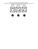

“Periscope” Lower Mirror (Mirror 4) Adjustment Diagram:
The diagram below illustrates the direction the Red Dot can be expected to move when the
indicated mirror adjustment screw is turned.
Top Allen
screw turned
clockwise
Lower right
Allen screw
turned clockwise
Lower left
Allen screw
turned clockwise
Diagram 4
44. Depress “Reset” to re-enable the axis, and to send the lens carriage back to the home
position
This completes the replacing the optics portion of this technical note.
Confirming the Alignment
45. Install the Alignment target in the lens carriage
46. Turn on the Red Dot pointer.
47. Depress the “X-Y Off” button on the control panel.
48. Depress the Go button, the carriage can now be moved around the table.
49. Move the lens carriage to the left rear corner (position 1) of the engraver.
50. Check to see if the Red Dot is centered on the target.
51. If the Red Dot is not centered on the target, using the Lower “periscope” mirror and the
“Periscope Lower Mirror (Diagram 4) Adjustment Diagram” above, adjust the Red Dot so
that it is centered on the target.
52. Move the lens carriage to the left front of the engraver.
53. Using the Upper “periscope” mirror and Diagram 3 so that the Red Dot pointer is centered
on the alignment target.


