EOS Vitae protect+ Скачать руководство пользователя страница 28

General Terms and Conditions of Service

I. Scope

Unless otherwise agreed in writing in a specific case, 

these terms and conditions of service shall apply to ser-

vice operations, including examining and repairing com-

plaints. All our existing or future legal relationships shall 

be governed solely by the following terms and condi-

tions of service. Our recognition of any conflicting terms 

and conditions of the Ordering Party shall be conditional 

upon our having given our express written consent to 

their applicability. We hereby expressly object to any 

terms and conditions of the Ordering Party contained 

in its General Terms and Conditions of Business or order 

confirmation. If order confirmations or deliveries are ac-

cepted without reservation, this shall not be deemed to 

constitute recognition of such terms and conditions. Any 

ancillary agreements or amendments must be confirmed 
in writing.

II. Costs

The Ordering Party shall bear the following costs in con-

nection with the service operation:

• 

De-installation/installation and electrical works (con-

nection / disconnection).

• 

Transportation, postage and packaging.

• 

Function testing and troubleshooting including in-

spection and repair costs.

There shall be no third-party billing.

III. Obligations / Ordering Party‘s coopera-

tion

The Ordering Party shall provide free-of-charge assis-

tance to the manufacturer in carrying out the service 

operation. 

In the case of a warranty claim the manufacturer shall 

provide the required replacement parts to the Ordering 

Party free of charge. 

IV. Service visit by the manufacturer

In the event that it is essential that a manufacturer em-

ployee carry out the service operation on site, this must 

be agreed in advance. Where the main reason for the ser-

vice call is not the fault of the manufacturer, any costs 

incurred shall be recharged to the Ordering Party after 

the service visit and shall be paid as per agreed payment 

terms.

V. Liability

The manufacturer shall assume liability in accordance 

with the currently applicable statutory regulations. The 

packaging for all of our products is designed for the ship-

ping of individually packed goods (pallet). We expressly 

point out that our packaging is not suitable for individual 

shipments via parcel post. The manufacturer shall accept 

no liability for damage incurred as a result of improper 

packaging in an individual shipment.

VI. Manufacturer‘s Guarantee

The manufacturer‘s guarantee shall apply only in the 

event that installation, operation and maintenance have 

been carried out in accordance with the manufacturer‘s 

specifications contained in the installation instructions 

and instructions for use. 

• 

The guarantee period shall commence from the date 

on which proof of purchase is provided and shall be 

limited, in principle, to 24 months.

• 

Guarantee services shall be performed only if the orig-

inal proof of purchase relating to the equipment can 

be presented.

• 

Any and all guarantee claims shall become void if 

modifications are made to the equipment without the 

manufacturer‘s express consent.

• 

Any guarantee claim shall likewise become void in 

the case of defects that arise due to repairs or inter-

ventions made by unauthorized persons or due to 

improper use.

• 

In the case of guarantee claims, the serial and article 

numbers must be indicated together with the product 

name and a meaningful description of the fault.

• 

This guarantee shall cover defective equipment parts, 

with the exception of usual wear parts. Wear parts are, 

among others, lamps, glass parts, heating elements 

and sauna stones.

• 

Only original replacement parts may be used within 

the warranty.

• 

Service visits by outside companies shall require a 

written order to be issued by our service department.

• 

The equipment in question shall be sent to our service 

department by the Ordering Party and at its expense.

• 

Electrical installation and connection works in the 

event of service or replacement shall be carried out at 

the Customer‘s expense and shall not be borne by the 

manufacturer.

Complaints in respect of our products shall be reported 

to the responsible authorized dealer and shall be exclu-

sively handled via the latter.

The manufacturers General Terms and Conditions of 

Business, which can be found at www.eos-sauna.com/

agb, shall apply in addition to the foregoing terms and 
conditions of service.


As of 08/2018

28

EN

Содержание Vitae protect+

Страница 1: ...t Infrarotw rmestrahler mit Dimmer Infrared radiator with dimmer D Montage und Gebrauchsanweisung Assembly and operating instruction EN RU Druck Nr print no 29344985 14 22 Technische nderungen vorbeha...

Страница 2: ...2 Deutsch 3 English 16 29...

Страница 3: ...e Daten 7 Zubeh r optional 7 Interne Verdrahtung 7 Anschlussplan mit Steuerger t InfraTec Premium 8 Hinweis zum Elektroanschluss 9 Montage 10 12 Mindestabst nde 10 Einbaubeispiele 11 Bedienung 13 Recy...

Страница 4: ...unktion beeintr chtigen und ist nicht zul ssig Jegliche nicht autorisierte technische Ver nderung f hrt zum Verlust der Gew hr leistung Sehr geehrte Kundin sehr geehrter Kunde Sie haben ein hochwertig...

Страница 5: ...angegeben Bitte fragen Sie Ihren Kabinenhersteller oder H ndler Allgemeine Sicherheitsbestimmungen F r die Regelung bzw Steuerung der Inf rarotstrahler ist ein geeignetes Steuerge r tzuverwenden Diese...

Страница 6: ...e dass der Emitter im Infra rot W rmestrahler keinen mechanischen Belastungen St e Druck ausgesetzt wird Ist der Emitter einmal gebrochen was aber beim bestimmungsgem en Ge brauch unwahrscheinlich ist...

Страница 7: ...Geh use fest verbaut Lagertemperaturen 20 C bis 50 C Umgebungstemperatur bis max 70 C Bestimmungsgem er Gebrauch IR W rmestrahler f r den Einbau in eine IR W rmekabine Verwendung nur inVerbindung mit...

Страница 8: ...1 IR Emitter 1 Power P1 IR Emitter 3 Power P3 max 1500 W max 1500 W max IR Gesamtleistung 3500 W IR Emitter 2 Power P2 Hinweis Bei Anschluss die maximal zul ssige Belastung der Ausg nge im Steuerger t...

Страница 9: ...ber diese Steckverbindung verbunden Alternativ kann eine optional er h ltliche IR Anschlussleitung Art Nr 94 7813 verwendet werden Bei der Montage sollten die Anschlussleitungen durch Leerrohre gef h...

Страница 10: ...optimale Abstand kann daher entsprechend unterschiedlich sein Mindestabst nde Der Mindestabstand von Strahleroberkante zur Kabinendecke muss 7 cm betragen Der Mindestabstand von Strahlerunterkante zur...

Страница 11: ...Wand nach oben Achten sie darauf dass die Strahlerseite mit Kabelanschluss nach unten zeigen muss Beachten Sie die Sicherheitsabst nde wie in den Abb 4 5 8 un 9 angegeben Montage F hren Sie zuerst die...

Страница 12: ...nde auf bzw direktvordemIR Emitterabgelegtwerden Brandgefahr ACHTUNG Der Strahler darf nicht im direkten Ab strahlbereich eines anderen Strahlers montiert werden Risiko des Ger tescha dens Einbaubeisp...

Страница 13: ...ei Funktionen Ein Aus Zum Ausschalten drehen Sie den Knopf nach links gegen Uhrzeigersinn bis zum Anschlag bis Sie einen leichten Klick h ren Der Strahler ist ausgeschaltet Zum Einschalten drehen Sie...

Страница 14: ...ycling Bitte diese Adresse zusammen mit der Montageanwei sung gut aufbewahren Damit wir Ihre Fragen schnell und kompetent beantwor ten k nnen geben Sie uns immer die auf dem Typen schild vermerkten Da...

Страница 15: ...kte sind f r den St ckgut versand Palette konzipiert Wir weisen an dieser Stelle ausdr cklich darauf hin dass unsereVerpackungen nicht f r den Einzelversand per Paketdienst geeignet sind F r Sch den d...

Страница 16: ...ries optional 20 Inner wiring scheme 20 Wiring diagram with control unit InfraTec Premium 21 Advice to electrical connections 22 Installation 23 25 Planning advice 23 Minimum distances Safety gaps 23...

Страница 17: ...claims immediately with the delivering transport company or please consult the supplier who provided the equipment to you Caution Risk of fire by incorrect installation Make sure to read the installat...

Страница 18: ...itable control unit to control theinfraredradiator Thecontrolunitmust bemountedinaccordancewiththeinstal lation instructions Attention Coveringtheinfraredradi ator causes a fire risk The installation...

Страница 19: ...hanical stresses knocks pressure Risk of break age Although breakage is unlikely if it is used properly if the emitter should break re place it with a new one Caution fire risk in the case of a broken...

Страница 20: ...g capacity firmly installed in the housing Storage temperature 20 C to 50 C Ambient temperature up to max 70 C Intended use IR radiator for installation in IR warming cabins To be used with a suitable...

Страница 21: ...max 1500 W max 1500 W max IR Gesamtleistung 3500 W Connection example with control unit InfraTec Premium Max total load for all outputs of the InfraTec Pre mium control unit 3500 W Notice By connecti...

Страница 22: ...in the control unit in stallation and operation manual If your control unit has the corresponding ca ble with plug connect the IR radiator using this plug Otherwise you can alternatively use the speci...

Страница 23: ...he effective heat coverage and contributes to a more pleasurable heat experience The intensity of Vitae emitters can be quick ly adjusted using an optionally available wall mounting IR dimmer item 495...

Страница 24: ...own ATTENTION Not suitable for horizontal installation and installation in the cabin ceiling Risk of fire due to heat congestion 200 1040 167 1020 60 15 Front view Dimensions in mm Wall cut out with r...

Страница 25: ...is no or inadequate ventilation behind and above the IR radiator the wood can overheat risk of fire Ensure adequate ventilation Do not block the space above the IR radiator so that the warm air can ri...

Страница 26: ...functions On Off To switch the radiator off rotate the dimmer anticlockwise until you hear a click To switch the radiator on rotate it clockwise to the right Adjust power Rotate the knob to the right...

Страница 27: ...your questions quickly and compe tently please provide the information printed on the type shield including the model item no and serial no in all inquiries Equipment commissioning date ______________...

Страница 28: ...roducts is designed for the ship ping of individually packed goods pallet We expressly point out that our packaging is not suitable for individual shipments via parcel post The manufacturer shall acce...

Страница 29: ...29 RU 30 32 33 33 33 33 34 35 36 38 36 36 37 39 40 ASB 41...

Страница 30: ...30 RU...

Страница 31: ...31 RU 8 EU60335 2 53 VDE0700 53...

Страница 32: ...32 RU...

Страница 33: ...S1 Dimmer 94 6596 1 5 94 7811 25 94 7812 3 94 7813 230 50 350 500 750 3 4 1040 x 200 x 60 0 8 10 1000 20 C 50 C 70 EOS EmoTec IR InfaStyle InfraStyle i InfraTec Classic EOS Econ I1 InfraTec Premium SB...

Страница 34: ...16A N N CTR L N L IR 1 IR 2 L LIGHT MAINS IR 3 Jumper KTY 10 5 L N N N L L S1 S2 Platine JP3 JP2 JP1 IR Emitter 1 Power P1 IR Emitter 3 Power P3 max 1500 W max 1500 W max IR Gesamtleistung 3500 W Infr...

Страница 35: ...35 RU 94 7812 2 2b 3 5 9 3 5 2b 1 3 5 2 4 7 9 6 8 1 3500 2 2b 94 7813 94 7811 94 7812 3500 5 9...

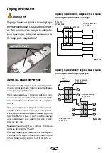
Страница 36: ...36 RU 3 750 50 350 500 15 4 min 4 cm min 7 cm min 4 cm Kabelanschluss muss unten sein min 4 cm 7 4 4 4 8 3...

Страница 37: ...37 RU 5 4 5 8 9 5 200 1040 167 1020 60 15 7 6 7 6...

Страница 38: ...38 RU 9 90 164 mm 167 mm 178 mm 45 mm 30 mm 8 164 mm 167 mm 178 mm Holzschutz 45 mm 40 mm 15 mm Mindestabstand Ger t muss hinterl ftet sein 5...

Страница 39: ...39 RU 10 10...

Страница 40: ...40 RU EOS Saunatechnik GmbH Schneiderstriesch 1 35759 Driedorf Germany EOC 108811 928 7 495 66 55 192 8 800 1000 539 info eos sauna ru www eos sauna ru...

Страница 41: ...41 RU ASB I II III IV V VI 24 www eos sauna com agb 08 2018...

Отзывы: