background image

4

3. 

Use a portable vacuum with HEPA filtration to re

-

move the loose dirt and organic matter. The filter 

should be 99.97% efficient at .3 micron particle 

size.

4.  If no microbial growth (mold) exists, thoroughly 

clean the fan and associated components with an 
industrial cleaning solution. Carefully follow the 
cleaning solution manufacturer instructions re-
garding use and disposal of their product.

5.  If microbial growth (mold) is present remove the 

contamination, and thoroughly clean the affected 

area with an EPA-approved sanitizer specifically 

designed for HVAC use. Carefully follow the san-
itizer manufacturer instructions regarding the use 
and disposal of their product.

6.  Rinse the affected surfaces thoroughly with fresh 

water and a fresh sponge to prevent potential cor-
rosion of metal surfaces.

7.  Allow the unit to dry completely before putting it 

back into service.

8.  Use caution to assure that any contaminated ma-

terial does not contact other areas of the unit or 
building. 

Properly dispose of all contaminated ma-
terials and cleaning solutions.

Important: If the microbial growth (mold) 
was found, the cause of the contamination 
must be determined and action taken to 
assure it does not reoccur. 

Fan Bearings

Bearing Set Screw Alignment

Align bearing setscrews. See 

Table 1 on page 22 

for 

bearing setscrew torque.

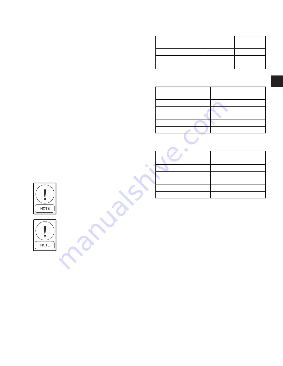
Fan Bearings should be lubricated with a lithium base 
grease which conforms to NLGI Number 2 for consis-
tency. See 

Table 2 on page 23, Table 3 on page 23, 

and Table 4 on page 23 

for recommended greasing 

intervals, operating range, and bearing grease capacities.

TABLE 2 - 

 RECOMMENDED  GREASING 
INTERVALS OF FAN BEARINGS

OPERATING

CONDITIONS

-20°F TO 

+140°F

140°F TO 

200°F

Clean, Dry

3-6 months

1-3 weeks

Dirty, Dry

1-3 months

1-4 weeks

Dirty, Wet, High Humid

1-4 weeks

1-14 days

TABLE 3 - 

RECOMMENDED GREASES FOR VARI-

OUS OPERATING RANGES

RECOMMENDED

GREASES

RECOMMENDED OPER-

ATING RANGE

Texaco-Multi Fak #2

-20°F to +250°F

Shell Alvania #2

-20°F to +250°F

Mobil Mobilux #2

-20°F to +250°F

Exxon Unirex #2

-20°F to +250°F

Exxon Beacon

-65°F to +250°F

TABLE 4 - 

FAN BEARING MAXIMUM GREASE 

CAPACITY

SHAFT SIZE IN INCHES

CAPACITY IN FL. OZ.

1/2 – 3/4

1/8

7/8 – 1-3/16

3/8

1-1/4 – 1-1/2

5/8

1-11/16 – 1-15/16

7/8

2 – 2-7/16

1-1/4

2-1/2 – 2-15/16

2

Lubricating the Fan Bearing

To lubricate the fan bearing, complete the following:

1.  Disconnect all electrical power to the unit, tag and 

lock out power source.

2.  Check grease lines for tight connections at the 

grease fitting.

3.  Using a manual low-pressure grease gun, add 

grease until a light bead appears at the bearing 
grease seal. Turn the fan wheel manually while 
adding grease.

Motor

General Inspection

Inspect the motor at regular intervals, approximately 
every 500 hours of operation or every three months, 
which ever occurs first. Operating conditions will vary 
the frequency of inspection and lubrication. Table 
5 (

Table 5 on page 25) 

lists recommended motor 

ENVIRO-TEC

23

SECTION 4 - PERIODIC MAINTENANCE AND SERVICE

FORM ET102.19-NOM1 (0521)

Содержание MQL B Series

Страница 1: ...MODEL MQL SERIES B INSTALLATION OPERATION MAINTENANCE INDOOR AIR HANDLING UNIT Supersedes ET102 19 NOM1 517 Form ET102 19 NOM1 0521...

Страница 2: ...r with and comply with all applicable governmental standards and regulations pertaining to the task in question SAFETY SYMBOLS The following symbols are used in this document to alert the reader to sp...

Страница 3: ...ushing or dismember ment injuries HOT PARTS HAZARDS Electric Resis tance heating elements must be discon nected prior to servicing Electric Heaters may start automatically disconnect all power and con...

Страница 4: ...y rigging and lifting equipment All assemblies must be adequately se cured during lifting and rigging by temporary supports and restraints until equipment is permanently fastened and set in its final...

Страница 5: ...rnal Isolation 15 External Isolation 15 Service Clearance 15 Panel Removal 15 General Piping 15 DX Connection Steps 16 In the field 16 Notes 16 Condensate Drain 16 Electrical Installation 16 INSPECTIO...

Страница 6: ...25 Mounting Straight Bore Sheaves 25 Mounting Split Tapper Sheaves 26 Adjust Variable Pitched Sheaves 26 Belts 27 Adjusting Belt Tension 27 How to Increase Belt Life 27 Coils 28 Steam Hot Water and Ch...

Страница 7: ...Sheaves 21 FIGURE 12 Sheave Alignment 22 FIGURE 13 Split Tapper Sheave Mounting 22 FIGURE 14 Belt Tension 23 TABLE 1 Minimum Hex Head Bolt Torque In Lb Ft Grade 5 Bolt 18 TABLE 2 Recommended Greasing...

Страница 8: ...THIS PAGE INTENTIONALLY LEFT BLANK ENVIRO TEC 8 FORM ET102 19 NOM1 0521 LIST OF FIGURES...

Страница 9: ...To ensure the assembled MQL modules are in the proper sequence each module has an identifying code and an airflow direction label The proper assembly sequence is listed on the supply fan nametag The...

Страница 10: ...balanced Rough handling may cause bearing misalignment and or shaft damage STORAGE To transfer equipment from truck to storage site refer to Rigging And Handling on page 9 If a forklift is used lift...

Страница 11: ...e actuator if the damp ers are the same size If the dampers are different sizes they must be driven by individual actuators and con trolled separately b Remove all shipped loose parts from job site to...

Страница 12: ...THIS PAGE INTENTIONALLY LEFT BLANK ENVIRO TEC 12 FORM ET102 19 NOM1 0521 Section 1 introduction...

Страница 13: ...ed from a ceil ing a base rail angle iron or channel must support the equipment The MQL product line is not designed to be suspended from the top of the equipment Be fore hanging the equipment all fie...

Страница 14: ...Left Hand Fan Access Door Figure 7 HAND IDENTIFICATION ENVIRO TEC 14 FORM ET102 19 NOM1 0521 Section 2 installation...

Страница 15: ...oil module is also isolated the piping must be isolated or have a flexible connection to prevent coil header damage due to equipment movement All piping wiring ductwork and external connections must b...

Страница 16: ...at pump condensing units but require the addition of fittings or refrigerant specialties to be furnished and installed by others Condensate Drain All condensate drains must have a trap installed This...

Страница 17: ...l Outside Air For Freeze Protection Proper Supply Return Grille Type Size Used Insulate All Ductwork As Required Verify All Ductwork Is Complete Dampers And Filters Are Installed Prior To Startup E EL...

Страница 18: ...INTENTIONALLY LEFT BLANK ENVIRO TEC 18 FORM ET102 19 NOM1 0521 Section 2 installation...

Страница 19: ...nly qualified individuals should perform these tasks Before entering the fan section make sure that the fan electrical power source is disconnected locked and tagged out in the OFF position 1 Check th...

Страница 20: ...pment 7 Manually rotate motor shaft to ensure that it ro tates freely 8 Replace all panels that were removed during in stallation 9 Momentarily apply power and check direction of rotation of motor sha...

Страница 21: ...sheaves Tighten sheave set screws to the proper torque see Table 1 on page 22 Check and adjust fan belt tension Tighten electrical connections Inspect coils for dirt build up or coil freeze up Every...

Страница 22: ...posal of their product 6 Immediately rinse the drain pan thoroughly with fresh water to prevent potential corrosion from the cleaning solution of the drain pan and drain line components 7 Allow the un...

Страница 23: ...ch conforms to NLGI Number 2 for consis tency See Table 2 on page 23 Table 3 on page 23 and Table 4 on page 23 for recommended greasing intervals operating range and bearing grease capacities Table 2...

Страница 24: ...of operation It is important to remember that this recommendation is base of average use Refer to Table 2 on page 23 for additional information Types of Grease A high grade ball or roller bearing grea...

Страница 25: ...5 The sheave should be close to the motor as possible with setscrew A in full contact with the key If the setscrew a is not fully in contact with key the sheave assembly could come off 4 Be sure that...

Страница 26: ...ft 8 Tighten capscrews progressively with wrench Dothis following a star pattern taking a partial turn on each capscrew successively until all are tight see Table 1 on page 22 for proper torque Do not...

Страница 27: ...be used to calculate the belt span LD14003 2 2 2 d D C Span C Center distance shaft to shaft D Driver sheave large sheave pitch diameter d Driver sheave small sheave pitch diameter 2 Calculate deflect...

Страница 28: ...urface of the coil reduces its ability to transfer heat that can result in reduced performance and increased operating energy costs If the dirt on the surface of the coil becomes wet which commonly oc...

Страница 29: ...10 Use caution to assure that any contaminated ma terial does not contact other areas of the unit or building Properly dispose of all contaminated ma terials and cleaning solutions Winterizing Water C...

Страница 30: ...ON LEVELS FAN SPEED RPM VIBRATION 800 or less 5 mils maximum displacement 801 or greater 20 in sec Maximum velocity Note Excessive vibration from any cause contributes to premature fan and motor beari...

Страница 31: ...l applications to prevent retaining con densate in the coil Generally the vacuum breaker is to be connected between the coil inlet and the return main the vacuum breaker should be open to the atmosphe...

Страница 32: ...se fresh air dampers if steam supply pressure falls below minimum specified Water Heating Coils 1 Water supply and water return connections extend through the end panel of the coil section All con nec...

Страница 33: ...k bear ing lubricant MOTOR STALLS Open phase Check line for an open phase Overloaded motor Reduce load or replace with larger motor Low line voltage Check voltage across AC line Correct voltage if pos...

Страница 34: ...ignment Loosen bearing setscrews and realign see Fig 10 Inadequate lubrication Grease bearing s LOW COIL CAPACITY CHILLED WATER Air is bypassing coil Prevent bypass with block offs Coil tubes are bloc...

Страница 35: ...5 ENVIRO TEC 35 Section 5 TROUBLESHOOTING FORM ET102 19 NOM1 0521...

Страница 36: ...Catalog ET102 19 NOM1 0521 Supersedes ET102 19 NOM1 517 ENVIRO TEC is a mark and or registered mark Unauthorized use is strictly prohibited 2021 Johnson Controls www enviro tec com...

Отзывы: