


Chapter 2: Installation
2-4
VHSIM-G6 User’s Guide
6.
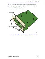
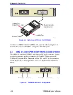
Refer to
Figure 2-2
and position the VHSIM-G6 behind the module
faceplate, above the connectors.
Figure 2-2
Installing the VHSIM-G6 in the Host Device
7.
Align the VHSIM-G6 connectors with the VHSIM connectors on the
module.
8.
Press down firmly on the VHSIM-G6 until the connectors slide all the
way onto the pins. Ensure that the standoffs on the interface module
align with the standoff screw holes on the VHSIM-G6.
!
CAUTION
When installing the VHSIM-G6, ensure that the pins on the
module align with the connector to prevent bending the pins.
This can damage both the VHSIM-G6 and the module.
Faceplate Mounting Screws
2549_36
Standoff
Connectors
VHSIM-G6
Standoff Screws
Connectors
(top view)
Standoff
Connectors
Cutaway view of connectors
Host Platform
VHSIM-G6
GPIM 1
GPIM 2
SP
Содержание VHSIM-G6
Страница 1: ...VHSIM G6 User s Guide VHSIM G6 GPIM 1 GPIM 2 9032549 03...
Страница 2: ......
Страница 22: ...Chapter 1 Introduction 1 6 VHSIM G6 User s Guide...
Страница 38: ...Chapter 4 Local Management 4 2 VHSIM G6 User s Guide...
Страница 40: ...Appendix A VHSIM G6 Specifications A 2 VHSIM G6 User s Guide...
Страница 44: ...Appendix B GPIM Specifications B 4 VHSIM G6 User s Guide...