background image

RPS Deployment Strategies

1-4 Introduction

RPS Deployment Strategies

The


RPS


can


be


deployed


in


a


variety


of


situations


with


mission

critical


applications.


For example:

For


use


in


a


voice


and


data


network


where


switches


are


connected


to


IP


phones


and


PCs.


Connecting


an


RPS


to


the


switches


can


prevent


voice


network


failures


caused


by


switch


power


failures.


For


use


in


traditional


data


10/100/1000


Ethernet


switches


carrying


mission

critical


data.


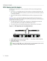
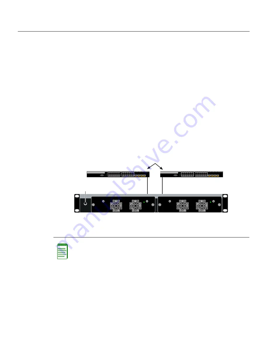
Figure 1

6


shows


an


example


of


the


RPS


providing


redundant


power


backup


for


two


SecureStack


C2


switches.


If


a


SecureStack


C2


switch


device


experiences


an


internal


power

supply


failure,


the


following


occurs:

1.

The


internal


DC

power


source


of


the


switch


device


is


immediately


switched


over


from


the


internal


DC

power


supply


to


the


RPS


DC

power


input.

2.

The


switch


device


saves


this


status


information


for


future


retrieval,


if


necessary.

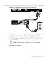
Figure 1-6  RPS Supporting Two SecureStack Switches

1

C2RPS-CHAS2 chassis (front view with two PSMs)

3

SecureStack C2 Ethernet switches

2

C2RPS-PSM Cables for 12 Vdc and status 
information from PSMs

Note: 

The C2RPS-PSMs used in C2RPS-CHAS2 are interchangeable with those used in 

the C2RPS-CHAS8 chassis available from Enterasys Networks.

CONSOLE

1

2

23

24

21

22

23

24

CPU

UP

RPS

MASTER

DOWN

C2G124-24

CONSOLE

1

2

23

24

21

22

23

24

CPU

UP

RPS

MASTER

DOWN

C2G124-24

C2RPS-CHAS2

C2RPS-PSM

Power

C2RPS-PSM

Power

À

Á

Â

Á

Содержание SecureStack C2 C2RPS-CHAS2

Страница 1: ...the model number C2xxxx xxP indicates a SecureStack PoE compliant device and is not compatible with this power system Precauci n El RPS no es compatible con switches SecureStack C2 con PoE No intente...

Страница 2: ......

Страница 3: ...sys Networks Inc 50 Minuteman Road Andover MA 01810 2005 Enterasys Networks Inc All rights reserved Part Number 9034091 01 April 2005 ENTERASYS ENTERASYS NETWORKS ENTERASYS MATRIX LANVIEW MATRIX NETSI...

Страница 4: ...This digital apparatus does not exceed the class A limits for radio noise emissions from digital apparatus set out in the Radio Interference Regulations of the Canadian Department of Communications Le...

Страница 5: ...entspricht den folgenden Richtlinien 47 CFR Parts 2 and 15 CSA C108 8 89 336 EEC EN 55022 EN 61000 3 2 EN 61000 3 3 EN 55024 AS NZS CISPR 22 VCCI V 3 VCCI Notice This is a class A product based on th...

Страница 6: ...td Nexus House Newbury Business Park London Road Newbury Berkshire RG14 2PZ England Conformance to Directive s Product Standards EC Directive 89 336 EEC EN 55022 EN 61000 3 2 EN 61000 3 3 EN 55024 EC...

Страница 7: ...VISIONS THE LICENSE THE DISCLAIMER OF WARRANTY AND THE LIMITATION OF LIABILITY IF YOU DO NOT AGREE TO THE TERMS OF THIS AGREEMENT OR ARE NOT AUTHORIZED TO ENTER INTO THIS AGREEMENT ENTERASYS IS UNWILL...

Страница 8: ...security controls as identified on the U S Commerce Control List or iii if the direct product of the technology is a complete plant or any major component of a plant export to Country Groups D 1 or E...

Страница 9: ...dge and agree that any breach of Sections 2 4 or 9 of this Agreement by You may cause Enterasys irreparable damage for which recovery of money damages would be inadequate and that Enterasys may be ent...

Страница 10: ...viii...

Страница 11: ...Cables and AC Power Cords 2 6 Appendix A Specifications C2RPS CHAS2 Chassis Specifications A 1 C2RPS PSM Specifications A 2 C2RPS PSM Redundant Power Supply Output Connector A 2 Compliance Standards...

Страница 12: ...f C2RPS CHAS2 Carton 2 2 2 2 Contents of C2RPS PSM Carton 2 2 A 1 C2RPS CHAS2 Specifications A 1 A 2 C2RPS PSM Specifications A 2 A 3 C2RPS PSM Redundant Power Supply Connector Pin Functions A 3 A 4 C...

Страница 13: ...d capabilities of the RPS components A general working knowledge of data communications networks is helpful when setting up an RPS C2RPS CHAS2 chassis with optional power supply modules Note In this d...

Страница 14: ...ties of the C2RPS CHAS2 chassis and optional power supply modules This chapter also provides the instructions for obtaining help from Enterasys Networks if needed Chapter 1 Introduction Instructions t...

Страница 15: ...ical Hazard Warns against an action that could result in personal injury or death due to an electrical hazard Riesgo Electrico Advierte contra una acci n que pudiera resultar en lesi n corporal o la m...

Страница 16: ...Conventions Used in This Guide xiv About This Guide...

Страница 17: ...an interruption in network traffic The end result is a more reliable network infrastructure protecting the network from a single source of failure from a network device power supply Depending on your...

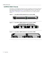
Страница 18: ...ssis Figure 1 1 SecureStack C2RPS CHAS2 front view without PSM _______________________________________________________________________________ Figure 1 2 SecureStack C2RPS CHAS2 front view with two PS...

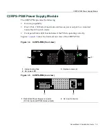
Страница 19: ...switch device Front panel Status LED that indicates if the PSM is operating correctly Figures 1 4 and 1 5 show the front and rear view of the C2RPS PSM Figure 1 4 C2RPS PSM front view Figure 1 5 C2RP...

Страница 20: ...ences an internal power supply failure the following occurs 1 The internal DC power source of the switch device is immediately switched over from the internal DC power supply to the RPS DC power input...

Страница 21: ...of your network environment layout cable type etc Network load and frame size at the time of trouble if known The device history i e have you returned the device before is this a recurring problem et...

Страница 22: ...Getting Help 1 6 Introduction...

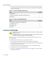
Страница 23: ...packing material protecting the devices 2 Verify the contents of each carton and compare the contents shipped with those listed in Table 2 1 and Table 2 2 Electrical Hazard Only qualified personnel sh...

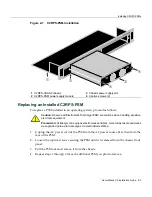
Страница 24: ...chassis front panel 3 Fasten the PSM to the chassis using the captive screws on the PSM front panel 4 Repeat steps 2 and 3 for each additional PSM 5 Proceed to Installing C2RPS CHAS2 into the Rack on...

Страница 25: ...it is released from the chassis front panel 3 Pull the PSM out and remove it from the chassis 4 Repeat steps 1 through 3 for each additional PSM you plan to remove 1 C2RPS CHAS2 chassis 3 Chassis pow...

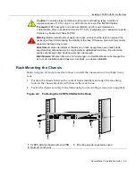
Страница 26: ...wer Cords on page 2 6 Guidelines for Rackmount Installation The installation site must be within reach of the network cabling and meet the requirements listed below Chassis placement close enough to c...

Страница 27: ...ventilaci n y evitar que el sistema se sobrecaliente deje un espacio m nimo de 10 16 cm 4 pulgadas con respecto a la parte delantera y trasera del chasis N POE Warning Before installing the chassis in...

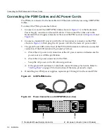
Страница 28: ...nto the main AC power outlet 3 The green Power LED on the front of the PSM will illuminate to indicate a successful connection If the LED remains off proceed as follows a Check the AC power cord conne...

Страница 29: ...ch device 4 Switch device Redundant Power Supply connector 2 PSM cable 5 AC power cord type varies depending on country 3 PSM Redundant Power Supply connector 6 AC power outlet with ground connection...

Страница 30: ...Connecting the PSM Cables and AC Power Cords 2 8 Installation...

Страница 31: ...Table A 1 provides the physical specifications for the C2RPS CHAS2 For information about Refer to page C2RPS CHAS2 Chassis Specifications A 1 C2RPS PSM Specifications A 2 C2RPS PSM Redundant Power Sup...

Страница 32: ...Range Output Voltage Output Current Maximum Output Power 47 63 Hz 85 264 Vac 12 Vdc 1 0 A min 8 5 A or 13 0 A max 102 W or 156 W continuous Physical Dimensions 19 6 H x 5 2 W x 25 7 D cm 7 7 H x 2 04...

Страница 33: ...Output 4 12 Vdc Output 5 12 Vdc Output 6 12 Vdc Output 7 Ground 8 Ground 9 No connection 10 No connection 11 Status 1 12 Status 2 13 Power good 14 Ground Table A 4 Compliance Standards Item Standard S...

Страница 34: ...Compliance Standards A 4 Specifications...

Отзывы: