Quick Start User Guide
v.1.2
IMPORTANT -
Ensure the power is disconnected
2.1 WIRED LAN
2.1.1 Plug the LAN cable into the LAN socket
4
2.2 WIRELESS LAN (WiFi)
2.2.1 Connect the included WiFi antenna to the WiFi antenna socket
5
(ensuring the antenna
is vertical)
2.3 PMR ANTENNA (GW425 & GW485 models only)
2.3.1 Connect the included PMR antenna and, if required, 90-deg adapter to the PMR antenna
socket
9
(ensuring the antenna is vertical)
2.4 Power the Gateway on
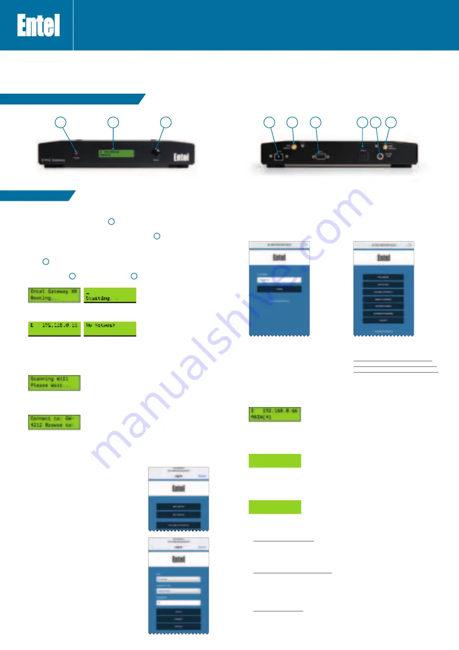
2.4.1 The red Power LED
1
will illuminate and the LCD
2
will display the following screens
(XX will be the Gateway model type):
2.4.2 Once the Gateway has started it will either show the Ethernet connection address (if an
Ethernet wire connected), else will display the ‘No Network’ screen:
If connected by Ethernet please skip to 2.5.5.
2.5 Connecting to a WiFi network
2.5.1 To enter the WiFi configuration mode press and hold the mode button for at least 5s.
Continue to hold and the display will indicate that it is scanning for available networks, the
button can then be released.
2.5.2 You now need to connect to the Gateway’s web configuration page.
The top line displays the Gateway’s SSID the URL is displayed on the bottom line (both
fields will scroll).
Use a smartphone or laptop to connect to the shown SSID and then, if the login page is not
automatically shown, browse to the indicated URL, http://192.168.43.1 (text will scroll on
the display).
If you want to exit WiFi configuration mode without connecting to a network, press and hold the
mode button for 5s.
2.5.3 WiFi Hotspot connection main screen
From the main Screen select ‘WIFI SETUP’
2.5.4 WiFi setup screen
Select a network from the SSID pull down.
Select its security type and enter the network
password.
To save changes tap ‘Apply’ then ‘Done, from the next
Screen.
2.7 Gateway ready mode
2.7.1 When the Gateway is connected to a server and ready it will display the group (channel) name it
is connected to and the number of users in the group (including the Gateway itself).
2.7.2 Gateway TX mode
When a GW is receiving a valid PMR voice group call (or triggered from the external GPIO +
voice audio if GWGG), it will ‘transmit’ (TX) to the PoC server on the default group/channel. The
display will show TX followed by the group name.
2.7.3 Gateway RX mode
When a GW receives a PoC voice group call (on the displayed default group), it will relay the
voice message over the programmed PMR channel (or send voice audio + PTT key logic if
GWGG). The display will show RX followed by the PoC user ‘alias’ of the calling device.
2.7.4 No server connection
If there is no connection to the server please check the following ports are open on your firewall:
2.7.4.1 To Entel’s provisioning server (provisioning.entelpoc.net):
1234 TCP
1235 TCP
1236 TCP
This is to enable remote programming of the Gateway by your Dealer.
2.7.4.2 To Entel’s E-PoC EMEA E-PoC server (emea1.entelpoc.net *)
80 TCP
443 TCP
4000 TCP
And your unique server port (which will be advised by your Dealer) that is TCP & UDP
* If you are using a different server please substitute the address accordingly.
2.7.4.3 To Entel’s update server (server1.entelpoc.net)
80
TCP
443 TCP
This is to allow for software updates. These ports must be opened to this server address no
matter which PoC server address you are using.
2.6 Connecting to the gateway via its connected network
Please connect to the IP address shown appending with :1234, i.e. in this example it would be
http://192.168.0.66:1234
You will be presented with a login screen:
Enter the default password ‘gateway’, which
should be changed when first configuring the
gateway (see 2.10 below).
Enter the password correctly and press enter
or tap LOGIN.
Choose an option by tapping on one of the
buttons.
You will note there is no option to setup
WiFi, this must be done via the gateway’s
direct (WiFi hotspot) mode (see 2.5 above).
Followed by the network connection main
screen
1.0 CONTROLS, INDICATORS & CONNECTORS
2.0 INSTALLATION
IMPORTANT
By using this product you agree to the terms and conditions of Entel’s E-PoC Service License which
can be viewed here:
www.entel.co.uk/EPoC_LICENSE
1.
Power LED
2.
LCD Display
3.
Mode / Settings button
4.
LAN cable socket
5.
Wireless LAN (Wi-Fi) antenna
socket
6.
External interface socket*
7.
Reset switch
8.
Power socket
9.
PMR antenna socket**
1
2
3
4
5
6
7
8
9
*Only fitted on GWUNI version.
**Only fitted on GW425 & GW485 versions.
E 192.168.0.66
TX Main
E 192.168.0.66
RX
User Alias


