Quick Start Guide
APPENDIX 2
LBS-751 Control
10
www.Entec-USA.com
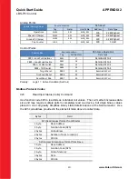
Analog Points
Special Analog Values
Source Location
03h Read
Tag
Scaler
User Table
Address
Data Type
Operations
MV01
0.01
MOD_001
126
32 Bit Signed
Phase PU (Amps)
MV02
0.01
MOD_003
128
32 Bit Signed
Ground PU (Amps)
MV03
0.01
MOD_005
130
32 Bit Signed
Trip Counter
SC03
1
MOD_065
190
16 Bit
Control Points
Control Bits
Source Location
05h Force Single Coil
Tag
Coil Address
Data Type
PB01 – Lock Push Buttons
RB01
27
Remote Bit Coil
PB02 – Loop Mode Enable
RB02
28
Remote Bit Coil
PB03 – CLOSE Switch
RB03
29
Remote Bit Coil
PB04 – TRIP Switch
RB04
30
Remote Bit Coil
Target Reset
RB05
31
Remote Bit Coil
Trip Count Reset
RB06
32
Remote Bit Coil
Reset Max / Min
RB07
33
Remote Bit Coil
Polarity:
Logic 1 = Active Condition (Set Coil)
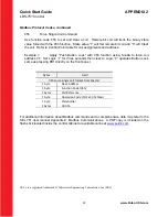
Modbus Protocol Codes
02h
Read Input Status (Coils) Command
Use function code 02h to read bits as individual coil values. The coil method increases data
size and may require multiple polls to completely read one device, but single binary values
placed in one coil greatly simplifies binary state determinations at the Scada master. Use
the 02h coil address provided in the status bit table above to collect data.
Bytes
Field
02h Read request format from Master
1 byte
Slave Address
1 byte
Function Code (02h)
2 bytes
Coil Address
2 bytes
Number of coils to read (
n
)
2 bytes
CRC‐16
02h Successful response format from Slave
1 byte
Slave Address
1 byte
Function Code (02h)
1 byte
Coils of data (
n
)
n
bytes
Data
2 bytes
CRC‐16


